Need : which tubes are in the unit. Can see the 4x 6dj8 but besides there is a smaller one... another smaller one and a bigger one cannot see the lettering ...
Hi max29,
This unit uses a 6CA4 for a rectifier (outboard box). A 6GC5 for the pass element (big tube) and a 6JC6 for the error amp. The voltge reference tube is a 5651. It glows orange normally in operation.
You should expect around 425~430 VDC in to the regulator and around 265 VDC out (one side of the 499 R resistors). The filiment of the 6GC5 is floated up to the output voltage through a pair of 10K resistors.
There is a current regulator diode (CR1) that should run around 45 VDC across it. It has a max voltage rating of 90 VDC that should never be exceeded, R51 sets this drop and is normally around 75K.
Try the 6922EH in this preamp. They are much better than the early 6DJ8 Nationals (terrible for microphonics) or the Sovtek 6922's that we went to just to get a quiet tube (freedom from the dreaded ringing). At the time, the Sovtek 6922 was the only option.
-Chris
Chris: Great reply ..thanks very much.. am checking on the voltages to get them aal accurate very good information..
Being a bit naughty i added a 6mfd pio to the 1e Cap on the pcb a 10mfd Spraque one. what a power ....
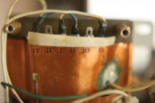
Know if the Trafo can be on 230volts directly... use a varistor now but the trafo has two pins not used so maybe...
url=http://img241.imageshack.us/my.php?image=trafo0077ta.jpg][img=http://img241.imageshack.us/img241/8962/trafo0077ta.th.jpg][/url]
Being a bit naughty i added a 6mfd pio to the 1e Cap on the pcb a 10mfd Spraque one. what a power ....
Know if the Trafo can be on 230volts directly... use a varistor now but the trafo has two pins not used so maybe...
url=http://img241.imageshack.us/my.php?image=trafo0077ta.jpg][img=http://img241.imageshack.us/img241/8962/trafo0077ta.th.jpg][/url]
Hi max29,
As for the transformer wiring. This should be a 115 / 230 V transformer. There are two primary windings and they appear to be in parallel in your picture (115V).
I would think, by looking at your picture, that you remove the two jumpers going to 1 and I1 (put them in heat shrink and keep the picture). Then connect via a wire 1 and I1. Before you make the connection, measure the windings for resistance. There should be an open between I2 and I3. The resistance between I1 and I3 should be close to I and I2 value, measure and map out the unused taps. Once they are connected you should have about twice that resistance across the line. I'm just reconfirming everything before you go ahead and complete the job. The phases should be correct. If you power up and it doesn't turn on right away, switch off immediately. Measure your voltages, you may have to change to higher taps on the transformer if the voltage is too high.
-Chris
Once you have the transformer wired correctly, recheck those voltages. Most of your readings will depend heavily on the correct AC being supplied to the transformer.
Remove the added caps until we have it working properly, then you can play.
-Chris
Remove the added caps until we have it working properly, then you can play.
-Chris
have the 230vdc on... anyone need the schematics for having 220v 230v let me know.
J1 is Ac line 220v . 1 is ac line 230/240v. Both having 12 and 13 inter-lined.
Can advise anybody to get this trafo with its feet off the metalhousing. Very bad.. many distortions are caused.Lifted it off and have it on block of corck/ foam... the unit improved 3 steps.
Just check the noise with a stethoscoop and hear yourself.
But have only 3 vdc across the diode CR1-D3.
Still over C51 feeding the cr1 have the 370 vdc.over it. 45 vdc across is a mystery to me at this moment
Replace it with a hexfred or...stealth or ...
Hi max29,
Your raw DC input should be around 430 VDC. What do you read?
The 45 V across CR1 and D3 (protection for CR1) is to provide operating compliance in case your AC supply varies. So the 45 V figure should be measured when your AC supply is at it's normal range. Adjust the value of R51 (75K nominal ) to give you this drop. Your raw DC should be close to 430 VDC as a check.
Do not start replacing stuff. The diode, CR1, is a constant current diode that is supposed to deliver about 1.6 mA worth of current. You could use an LED / bipolar transistor setup to improve the performance. I doubt that would make a worthwhile difference.
At any rate, get this thing working properly before you start messing with the design.
-Chris
Hi max29,
430 - 377 + 3 = 56. About what you should have across the current regulator diode.
Can you adjust the primary taps to correct this?
-Chris
430 - 377 + 3 = 56. About what you should have across the current regulator diode.
Can you adjust the primary taps to correct this?
-Chris
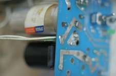
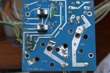
Chris..if there has to be 430vdc has to come from the powerunit so went over there at » 2 « are the two wires starting carrying the 430 to the unit...There has been some strange soldering been going on..as you can see but no 430vdc starting there....
Attachments


Hi max29,
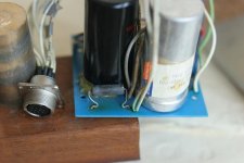
Well, it looks like there has been heat, never a good sign.
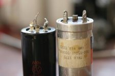
Step 1: Clean up the PCB, R70 (500R 5W) might be bad. The two caps are rated at 100uF 500V. I've always thought the first cap after the rectifier was too high in value. Take it down to 47uF or lower.
Step 2: Remove the tube socket and clean the PCB well. The PCB tends to track and burn. Clean it well and resolder. Clean off all the flux. If you have high voltage dope, use it.
Step 3: Resolder connections. Remove the old solder first and clean the oxides off the leads. Resolder using solder flux if you can. I see a couple bad joints. Check closely the heater leads to both the power supply PCB and the preamp PCB. They are known to go bad and cause much trouble.
The pad marked "2" is the HT lead into the preamp. I can't remember how many leads, but two seems odd. I'll have to see one and check. Look in the preamp for these leads. trace with an ohm meter. Test the 6CA4 while you are at it. It may be damaged. Use a good replacement, Sovteks have been okay.
-Chris
Well, it looks like there has been heat, never a good sign.
Step 1: Clean up the PCB, R70 (500R 5W) might be bad. The two caps are rated at 100uF 500V. I've always thought the first cap after the rectifier was too high in value. Take it down to 47uF or lower.
Step 2: Remove the tube socket and clean the PCB well. The PCB tends to track and burn. Clean it well and resolder. Clean off all the flux. If you have high voltage dope, use it.
Step 3: Resolder connections. Remove the old solder first and clean the oxides off the leads. Resolder using solder flux if you can. I see a couple bad joints. Check closely the heater leads to both the power supply PCB and the preamp PCB. They are known to go bad and cause much trouble.
The pad marked "2" is the HT lead into the preamp. I can't remember how many leads, but two seems odd. I'll have to see one and check. Look in the preamp for these leads. trace with an ohm meter. Test the 6CA4 while you are at it. It may be damaged. Use a good replacement, Sovteks have been okay.
-Chris
- Home
- Amplifiers
- Tubes / Valves
- Counterpoint SA 5.1