Hi max29,
Replace that resistor. That should bring your B+ up a little I would think. From the look of those wires, that's what I thought you would find.
It's a nice sounding preamp. Worth rebuilding. Stick a new 6CA4 in it if you are going to keep it. Bypass C50 in the preamp (1uF 400V) with a film type, or just replace C50 with a 1uF film cap (better). Once you have the correct B+, the rest should be just mild adjustments.
Do reduce the value of the first filter cap. There is no reason to beat up that rectifier like that.
-Chris
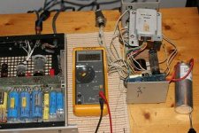
Resoldering done still no 430 v in on the HT ..
The fuse is a 2-1 / 2A ?
The metal can cap was gone totaly 0.06 mfd left..replaced the with the 500v 100-100 and a pio 40 mfd ...
The fuse is a 2-1 / 2A ?
The metal can cap was gone totaly 0.06 mfd left..replaced the with the 500v 100-100 and a pio 40 mfd ...
C51 340 vdc C50 340 vdc
c52 85.3
But still the 602 R is in there
So have less vdc then yesterday 377 ... funny little thing...
thanks Chris give me your paypal account and get me a copy of the schematics of this thing..... I like very much and keep it
C 50 is the red MKP 10 uf at the entrance ain t it... should be the best may a auricap will be fine there..
Foat or ground chassis switch does what...?
Hi max29,
C50 is across the B+ input to the regulator section.
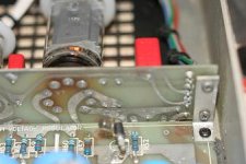
C77 is in the power supply off the cathode (P3) of the 6CA4. What's the voltage there?
C78 is the cap right after your high value (602R) resistor. How much voltage is across that cap?
The other voltages don't matter at this point in time. You should have 365 VAC from ground to each plate of the 6CA4 (pins 1 and 7). You need to get this voltage right before the rest can fall in line. The 500R 5W resistor also needs to be replaced. After than we can worry about the other voltages.
The ground switch will connect or float the circuit ground to the chassis ground.
Auricaps are a waste of money IMHO. Just install a good polprop or polyester film cap. You'll be miles ahead with that.
No Paypal account. 😉
-Chris
C50 is across the B+ input to the regulator section.
C77 is in the power supply off the cathode (P3) of the 6CA4. What's the voltage there?
C78 is the cap right after your high value (602R) resistor. How much voltage is across that cap?
The other voltages don't matter at this point in time. You should have 365 VAC from ground to each plate of the 6CA4 (pins 1 and 7). You need to get this voltage right before the rest can fall in line. The 500R 5W resistor also needs to be replaced. After than we can worry about the other voltages.
The ground switch will connect or float the circuit ground to the chassis ground.
Auricaps are a waste of money IMHO. Just install a good polprop or polyester film cap. You'll be miles ahead with that.
No Paypal account. 😉
-Chris
good news getting allready 383 over C51 (must be the two new caps in powersupply they load up) ...
((is quit alive this thing..... ain t he.... he does not start hitting me in an hour or so..does he ..))
no.... he started at 340 now after an hour is at 383 ...not bad
of course you can always Skype at verdi29
((is quit alive this thing..... ain t he.... he does not start hitting me in an hour or so..does he ..))
no.... he started at 340 now after an hour is at 383 ...not bad
of course you can always Skype at verdi29
Chris ..good news again
Have 12.87 ± across CR1/D3
I resolder over there as well in one hour as you advised to do the pn 3010 pw board...
Maybe 5 vdc more cause solder is from the middleages
Have 12.87 ± across CR1/D3
I resolder over there as well in one hour as you advised to do the pn 3010 pw board...
Maybe 5 vdc more cause solder is from the middleages
got 439 vdc form 3 kath. to 9 Anode of the 6ca4 on powersupply board
donot know if is going to get higher
Should he run on 460 or so ... the 6ca4
donot know if is going to get higher
Should he run on 460 or so ... the 6ca4
Hi max29,
Things are starting to go your way. 😀
You are about 10 VDC lower at the 6CA4 pin 3 B+ point. That's fine, just a slight adjusment on R51.
The 500 R resistor should then be the last of your troubles. So put the preamp aside until that part is installed. Size R51 (now 75K ?) to drop about 45 V across CR1. This is a constant current leg, therefore you make R51 smaller to increase the voltage across CR1. You should see all your supply voltages in the proper range as well.
Replace the rectifier (6CA4) since it's over 10 years old I bet. Do this before adjusting the R51 value.
-Chris
alsoo the R 18 and R 08
channel A and B line
has put a silver mica across of 0.004 Nf.
Any idea why that value and why across this resistors
- R 51 is a 106 K --or ... colors are wearing out
seems a 0.5 watt maybe take 1 watt thre as well
channel A and B line
has put a silver mica across of 0.004 Nf.
Any idea why that value and why across this resistors
- R 51 is a 106 K --or ... colors are wearing out
seems a 0.5 watt maybe take 1 watt thre as well
Hi max29,
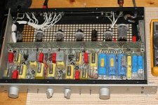
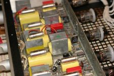
The metal shields help keep the noise and crosstalk down. I've never removed them to see how effective they are. In a Nakamichi CA-7, I had one channel S/N ratio improved on the order of 8 dB by installing an electrostatic shield. It then equaled the other channel and handily beat it's rated S/N ratio. It did before but the "bad" channel was within a couple dB.
Don't forget that the large caps have a large surface area to pick up noise with.
The small caps you are talking about may cut the frequency response in the ultrasonic region. Could be the output stage was unstable with certain loads. If you look, R8/108 are in series with a 20 nF cap, the 7 nF cap is in parallel with that. Mr. Elliot isn't the best designer (designs by ear) and therefore there may be a better way to do this. But it works as it is, so don't mess with it unless you have trouble. You would need to tear the entire circuit apart and investigate everything. I did that with an SA-100. Everything lead to something else. There's more for me to do on that still. Long process.
-Chris
- Home
- Amplifiers
- Tubes / Valves
- Counterpoint SA 5.1