great advice chris learn a lot from your doings also...
have to find the 500R cause it is hard to find a good one here
so only put in some E88cc tubes much better as you said but like the 6922Eh more .. hard to get here impossible ..
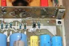
About his construction...
When you touch a tube you hear the noise all the way to in to the speakers that is definitely something am going look at when have the voltage in order..
Have tuberings on seems good idea with so much rumble//noise being transported all the way
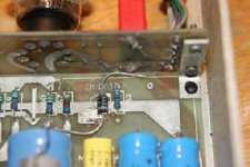
Under CR1// D3 there is alsoo a little resistor is that there as well
so current going from C51 first hits this resistor before entering d3//cr1 ...
Got your trafo with a cork underneath... Took the cork piece away and was blown away with the devalution in sound directly
when i tapper a tube a bit that convinces me even more about getting some more material to dampen resonance ...
The trafo is so clear so he must have made the same mistake with the
aal the tubes lined up or interconnected from tube panel to base-panel
have to find the 500R cause it is hard to find a good one here
so only put in some E88cc tubes much better as you said but like the 6922Eh more .. hard to get here impossible ..
About his construction...
When you touch a tube you hear the noise all the way to in to the speakers that is definitely something am going look at when have the voltage in order..
Have tuberings on seems good idea with so much rumble//noise being transported all the way
Under CR1// D3 there is alsoo a little resistor is that there as well
so current going from C51 first hits this resistor before entering d3//cr1 ...
Got your trafo with a cork underneath... Took the cork piece away and was blown away with the devalution in sound directly
when i tapper a tube a bit that convinces me even more about getting some more material to dampen resonance ...
The trafo is so clear so he must have made the same mistake with the
aal the tubes lined up or interconnected from tube panel to base-panel
Hi max29,
If you have the original National 6DJ8's, they were very bad for microphonics. Almost anything is better. Here it is easier for me to get 6922EH, and I prefer them. I have not tried E88CC's. I imagine they would be good also. Use them. 😉
There should be no resistor in between CR1 and C51. Remove it if it looks like it was added by a technician.
The rubber grommets used for suspension are probably bad by now. By all means, find something to dampen the chassis. Do not block airflow.
Put some resistance in parallel with the bad 500R resistor to make the total resistance 500R. Go ahead and measure across CR1 and check your B+ voltages.
-Chris
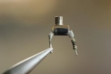
so the diode is a 1n 400 ....
or
Soldering this off i noticed that one side was on the board the other leg went through the pcb .... Is that correct
The leg with the resistor on went THROUGH the pcb
The other was soldered on the surface only is that mean to be
or
Soldering this off i noticed that one side was on the board the other leg went through the pcb .... Is that correct
The leg with the resistor on went THROUGH the pcb
The other was soldered on the surface only is that mean to be
Attachments

... has put a another diode allready.. no more resistor as well but get only 13 vdc across cr1//d3..
Over C77 it stays at 420
Over c78 stays 389
C51 376 vdc
Between C50 (1uf400v MKP10) + »»» - =390vdc
Maybe get no enough juice from the trafo
should be more then the 430 because resistor is changed to 460R
as well
Over C77 it stays at 420
Over c78 stays 389
C51 376 vdc
Between C50 (1uf400v MKP10) + »»» - =390vdc
Maybe get no enough juice from the trafo
should be more then the 430 because resistor is changed to 460R
as well
Hi max29,
CR1 is a 1N400x series diode ??! It's a 1.6 mA current regulator diode! That explains the resistor! Do Not Apply Power!!
A J506 or J507 from http://www.linearsystems.com/datasheets/J500.pdf would work. I used to buy the original from Electrosonic as a Motorola part, but they may be discontinued. This may be replaced by a constant current source circuit for enhanced performance.
CR1 = <part number not listed!> 1.6 mA, 100 V breakdown.
D3 = 1N5378 91V 5W zener diode. It's there to protect CR1 and normally never conducts.
I'm not exactly sure what you have posted, but please ensure these parts are installed before doing anything else at all.
-Chris
CR1 is a 1N400x series diode ??!
It's a 1.6 mA current regulator diode! That explains the resistor! Do Not Apply Power!! A J506 or J507 from http://www.linearsystems.com/datasheets/J500.pdf would work. I used to buy the original from Electrosonic as a Motorola part, but they may be discontinued. This may be replaced by a constant current source circuit for enhanced performance.
CR1 = <part number not listed!> 1.6 mA, 100 V breakdown.
D3 = 1N5378 91V 5W zener diode. It's there to protect CR1 and normally never conducts.
I'm not exactly sure what you have posted, but please ensure these parts are installed before doing anything else at all.
-Chris
chris.. yes work ahead...thanks for the advice
Because had to undo the resistor there could not find any data on the diode ...but have back inplace short legged
Took as well the resistor out between the 5651.and the 6cj..reads only 18 R..... colours are gone but indicate much more
Have a gold and red left in between a brown and gold
Because had to undo the resistor there could not find any data on the diode ...but have back inplace short legged
Took as well the resistor out between the 5651.and the 6cj..reads only 18 R..... colours are gone but indicate much more
Have a gold and red left in between a brown and gold
tell me more abou the constant current source supply how is that and somewhere to see
meaning the Sod types
meaning the Sod types
Hi Max29,
There are many examples. The best known may be the LED reference type and the "ring of two" type. Search for "constant current source" at this link. Basically the search bitton at the top right of your page at the top of a thread.
What you currently have in there is a constant current diode (because it has two leads only, I think it's really a FET of some kind.
The proper part looks like a glass diode with a band at one end.
-Chris
the resistor between tube 5651 and the 6jc6a is valued at....
Think you get in troubles with the J 506 regulating diode cause they only go up 50 vdc as far i can see
Think you get in troubles with the J 506 regulating diode cause they only go up 50 vdc as far i can see
Hi Max29,
My gosh! You're right!
Sorry about that. I was trying to second source a part for you (too quickly).
I'm sure someone must still make or source that part. Did you have any luck searching for current sources?
You can test the existing part with a small power supply. Stick the diode in series with a 1K resistor (to make things easy) and apply up to, say 20VDC. Ramp the voltage up slowly while measuring across the 1 K resistor. One way (polarity of diode) you should see around 1.6 V across the resistor that does not increase much as the voltage is increased further.
-Chris
TVS..what about a transient voltage suppression diode as a replacement ..
uni-directional 150v is the lowest can get fairchild at least 1v5ke150a see alsoo mouser parts TVS.
Do you think the 150 v one is too high (100v now over the 1n5378 5watt) ?
TVS= two mutually opposing zeners in series with o.a. connected in parallel with the circuit to be protected
Thedevice operates by shunting excess currewnt when the induced voltage exceeds the zener breakdown potential...
Any one has an opinion on this one as a replacement
Hi Max29,
What you need here is a device, or circuit with a 100V breakdown minimum. It needs to supply a current close to 1.6 mA with reasonable isolation to the supply. A resistor will not cut it.
-Chris
No, wrong device. You need to generate a constant current here. Please test the original part, it may be fine (I hope).TVS..what about a transient voltage suppression diode as a replacement ..
What you need here is a device, or circuit with a 100V breakdown minimum. It needs to supply a current close to 1.6 mA with reasonable isolation to the supply. A resistor will not cut it.
-Chris
Chris.... Coming in from the C51 is 378 vdc
across ´our´ TVS should be reduced to about 50 volt
but fluctuating all the time
This is just a supplypower = extra juice from the C51 Cap coming because the it is going to the P 9= Anode of the 6GC5.
P9 is mainly supplied by the wire 2 coming from the power supply directly
So he is feeding the P9 anode of the 6gc5 with two supplies right ...
Hi Max29,
It is critical that the current through this network is controlled. CR1 does that. What ever is in that location must withstand about 100V. This is a fault condition not normally encountered. D3 is only a protection device.
So, CR1 is a device that regulates the current to a constant 1.6 mA over a voltage range that may be bounded from 15V up to 90 V. The normal operating range varies a little (say +- 10 VDC) around 45 V across the device.
Test the diode you already have. You may be fine.
-Chris
No, C51 (12uF 350V) is fed through CR1 (constant current of 1.6 mA), it feeds R51 (75K normally, can vary) and the plate of the 6JC6 (error amp, pin 7). This junction also goes to pin 3 of the 6GC5 through a 681R resistor. The cathode of the 6JC6 is sitting on a 5651 gas voltage regulator tube. That's your reference for the voltage regulator circuit. This tube is also fed from the output of the regulator through a 182K resistor. This resistor swamps current variations through the 6JC6 error amplifier.Coming in from the C51 is 378 vdc
It is critical that the current through this network is controlled. CR1 does that. What ever is in that location must withstand about 100V. This is a fault condition not normally encountered. D3 is only a protection device.
So, CR1 is a device that regulates the current to a constant 1.6 mA over a voltage range that may be bounded from 15V up to 90 V. The normal operating range varies a little (say +- 10 VDC) around 45 V across the device.
Test the diode you already have. You may be fine.
-Chris
Hi Max29,
Forgot to answer your other question ....
-Chris
Forgot to answer your other question ....
I believe you found both wires going to the same point on each end. I don't recall there being two wires. Possibly he had an extra wire and decided to use it there?? Count it as one wire since it begins and ends at the same place.So he is feeding the P9 anode of the 6gc5 with two supplies right ...
-Chris
Did not solder the cr1/d3 in yet cause want to be sure
the diode cr1//d3 has the grey ring/band at the side of the tube board meaning current is oNLY flowing from the C51 to the P9 of 6gc5
Is that at yours the same
What your are saying current coming in from the wires to P9 of the 6gc5 is then in oppositio with how the diode cr1 is soldered on should be that the band on the diode is at the side of the + of the 10uf c51 cap.
am i right
Attachments
Hi Max29,
The band on the zener (D3) points towards pin 9 on the 6GC5. Follow the silk screening on the board.
I do not have a PCB layout. I'll have to take a picture of the next one I do. Until then, measure continuity to be sure. Test the current regulator diode as I suggested earlier.
Testing is of much more value to you than anything I can tell you unless I have one of these right in front of me.
-Chris
- Home
- Amplifiers
- Tubes / Valves
- Counterpoint SA 5.1