anatech said:Hi Chris,
I was trying to alert you to look at the ground reference for your measurement. So everything is okay?
Not sure I understand what or how to do what you are asking? The heater + is grounded at the common ground for the preamp on the tube PCB (where the umbilical comes in pins 3/10 and 4 are tied together there by M.E.). This should be at the same potential as the main pcb ground for the preamp itself. When I look at the regulator output itself (which is tied to common) I can barely see a very slight amount of ripple (out to the limit of my scope), so something is modulating the supply a bit... I figured it was the amount of current it has to source. Could I rig up a dummy load... I have some 8 ohm 10watt or better resistors around, maybe put two in parallel and see what the heater supply looks like into those?
No, I haven't done the pcb yet. The old one is still serviceable, just the pads around the main caps are a bit toasty. I thought I would either do a home etched one or get one (or more) commercially done this winter.anatech said:I am pretty sure you will be more than a little happy with it when you're done. You are using your new power supply PCB aren't you?
-Chris
Thanks and Happy Holidays to you!
Chris
Hi Chris,
I was suggesting that your dropping voltage reading could possibly be the result of a difference in reference points in teh circuit or in your measurment test points.
Really, I'm trying to understand your reading changes also. Simple explainations are normally the correct ones.
Best of the Season and Merry Christmas to you as well! Let me know if you see anything else odd in there.
-Chris
Hi Chris,
This is more a scope question: I took a look at the raw B+ (the 430V right by the zener). When I set the scope to AC and cranked the V scale down, the trace was bouncing all over the place vertically (not staying centered). Is this caused by a leaky coupling cap on my scope input? I suppose I could toss a suitable film cap inline with the scope probe, but was just curious as to what was causing this.
Chris (Pars)
Hi Chris,
That may be related to your supply voltage bouncing around. Stick one channel on the raw B+ and the other where you had it. See if they drift up and down together.
I'm hoping your 'scope input cap is not leaky. This would be a very bad thing.
-Chris
That may be related to your supply voltage bouncing around. Stick one channel on the raw B+ and the other where you had it. See if they drift up and down together.
I'm hoping your 'scope input cap is not leaky. This would be a very bad thing.
-Chris
Hi Chris,
For safety (of the scope) should I put a film cap in series with the probe?
By raw B+, you mean in the PSU itself? I was looking at the more or less raw B+ in the preamp itself (on the zener input).
By bad thing, you mean as far as fixing it? Or other? (just what I need, something else to fix 😱 ).
Chris (Pars)
btw, I saw kbk's SA220 on audiogon that you apparently helped him fix. I worked on my brother's a few months ago (startup timing circuit was flaky, so I fixed it). Those things are a major pain in the *** to get at the bottom of the pcb
For safety (of the scope) should I put a film cap in series with the probe?
Stick one channel on the raw B+ and the other where you had it. See if they drift up and down together.
By raw B+, you mean in the PSU itself? I was looking at the more or less raw B+ in the preamp itself (on the zener input).
I'm hoping your 'scope input cap is not leaky. This would be a very bad thing.
By bad thing, you mean as far as fixing it? Or other? (just what I need, something else to fix 😱 ).
Chris (Pars)
btw, I saw kbk's SA220 on audiogon that you apparently helped him fix. I worked on my brother's a few months ago (startup timing circuit was flaky, so I fixed it). Those things are a major pain in the *** to get at the bottom of the pcb
Hi Chris,
Your probes are rated at 500VDC or AC peak are they not? If so you should be fine.
Your raw B+ will tend to drift up and down a fair amount. Don't worry about it as that is normal. That is also why we use a regulator.
Disregard any comments pertaining to leaky 'scope input caps.
-Chris
Your probes are rated at 500VDC or AC peak are they not? If so you should be fine.
Ah! I misunderstood. I thought you were measuring across the zener.By raw B+, you mean in the PSU itself? I was looking at the more or less raw B+ in the preamp itself (on the zener input).
Your raw B+ will tend to drift up and down a fair amount. Don't worry about it as that is normal. That is also why we use a regulator.
Disregard any comments pertaining to leaky 'scope input caps.
They sure are! Most people don't understand that until they actually have to get in there. I see many where the work is done from the top of the board - messy.Those things are a major pain in the *** to get at the bottom of the pcb
-Chris
Hi Chris,
FInally got around to biasing the line section using RMAA using an M-Audio Firewire Audiophile external box. Went well and wasn't too painful. I biased it at high gain setting, volume all the way up. THD went from around 0.25% to 0.005% (16 bit/44.1kHz testing) or 0.011% using 32 bit/192kHz, assuming RMAA's figures are believable... I only care about the relative values.
Listening to it, it definitely sounds the best it ever has. Hum is very low (high gain, volume cranked I have to get within 6" of the tweeter, more like 2-3" to hear it). Funny thing... switching back to low gain, the hum is more pronounced (still good)? I wonder if this is a result of setting bias at the highest gain? I may try going back and forth between high and low gain, and getting the THD figure the best I can between the two. Typical listening is on the low gain setting with the volume about half way up.
Also, I got the 47uf Cerafine and put it in. Will the 100uf that I pulled out of there work OK for the HV reg section (C55, last cap for the second phono stage , shown as a 200uf in schematic)? The 220+220uf Cerafines I have in the HV reg section right now (C55, C57 and C58) are just too large physically (35mm x 102mm).
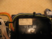
One other thing... the transformer in this has a handwritten sticker on it (see pic) saying SA5. According to the service manual, the transformers between the SA5 and SA5.1 were changed due to the move from 12V to 6V heaters. The sticker makes it look like mine has been replaced by a shop other than Counterpoint. Have you seen things like this come from the factory?
Thanks, and thanks again fro all of your help! It is most appreciated! Happy holidays!
Chris (Pars)
FInally got around to biasing the line section using RMAA using an M-Audio Firewire Audiophile external box. Went well and wasn't too painful. I biased it at high gain setting, volume all the way up. THD went from around 0.25% to 0.005% (16 bit/44.1kHz testing) or 0.011% using 32 bit/192kHz, assuming RMAA's figures are believable... I only care about the relative values.
Listening to it, it definitely sounds the best it ever has. Hum is very low (high gain, volume cranked I have to get within 6" of the tweeter, more like 2-3" to hear it). Funny thing... switching back to low gain, the hum is more pronounced (still good)? I wonder if this is a result of setting bias at the highest gain? I may try going back and forth between high and low gain, and getting the THD figure the best I can between the two. Typical listening is on the low gain setting with the volume about half way up.
Also, I got the 47uf Cerafine and put it in. Will the 100uf that I pulled out of there work OK for the HV reg section (C55, last cap for the second phono stage , shown as a 200uf in schematic)? The 220+220uf Cerafines I have in the HV reg section right now (C55, C57 and C58) are just too large physically (35mm x 102mm).
One other thing... the transformer in this has a handwritten sticker on it (see pic) saying SA5. According to the service manual, the transformers between the SA5 and SA5.1 were changed due to the move from 12V to 6V heaters. The sticker makes it look like mine has been replaced by a shop other than Counterpoint. Have you seen things like this come from the factory?
Thanks, and thanks again fro all of your help! It is most appreciated! Happy holidays!
Chris (Pars)
Attachments
Hi Chris,
Your distorton readings are believeable using the high gain setting. Jumpered for low gain, the distortion will be higher. You are not using the fet as an input in that configuration. Since you have the ability to rebias it, set the gain the way you will use it and change it as required (like when you change tubes).
There is really no point in replacing the phono filters with the old 100uF caps. You would gain more by bypassing them.
Yes, those preamps do sound good once they are tuned up. I had no doubt you would be happy at the end of all this.
Happy Holidays Chris!
-Chris
Your distorton readings are believeable using the high gain setting. Jumpered for low gain, the distortion will be higher. You are not using the fet as an input in that configuration. Since you have the ability to rebias it, set the gain the way you will use it and change it as required (like when you change tubes).
There is really no point in replacing the phono filters
with the old 100uF caps. You would gain more by bypassing them.Yes. This is quite normal from the factory.One other thing... the transformer in this has a handwritten sticker on it (see pic) saying SA5
Yes, those preamps do sound good once they are tuned up. I had no doubt you would be happy at the end of all this.
Happy Holidays Chris!
-Chris
anatech said:Hi Chris,
Your distorton readings are believeable using the high gain setting. Jumpered for low gain, the distortion will be higher. You are not using the fet as an input in that configuration. Since you have the ability to rebias it, set the gain the way you will use it and change it as required (like when you change tubes).
There are no FETs in this. The gain switch I believe puts the 2nd section of the line tube in... low gain uses the first section only (this was one of the SA5.1 changes... the SA5 did not have the gain switch). I will play around with biasing at a different setting (gain, etc.).
Any opinion on the change in hum? Before, it had always been linear (higher gain/pot setting = more hum). 😕
This isn't really an old cap... it is a 100uf 500V Cerafine. I'll probably use it in the future and pull the 220+220/350V dual caps. BTW, I started to bias the phono stage, but aborted on it. It appeared that I would wind up with the pots for each channel almost fully clockwise, which seemed odd (as in something isn't right/I'm not doing something right). I was using 1kHz for the testing. After re-reading the service manual, it appears that 100Hz, not 1kHz, is what they recommend for the phono section?anatech said:There is really no point in replacing the phono filters
Yes. This is quite normal from the factory.
anatech said:
Yes, those preamps do sound good once they are tuned up. I had no doubt you would be happy at the end of all this.
Happy Holidays Chris!
-Chris
I'm glad you thought so... there were times I was certain I was going to wind up with a hunk of junk for the trash bin... possibly still smoking

Chris (Pars)
Hi Chris,
Sorry, my mind was on an SA-5000.
When you started talking about the really low distortion figures I switched mentally to the newer preamp. I didn't believe the low distortion figures I was getting with those, not as low as you are stating but that was with nasty National tubes.
The only difference in this model is that in low gain the input is attenuated through a 32 K resistor (17 K to ground). Both sections are in use all the time. The distortion adjustments have no effect except that you may get a high signal level in one and you'd be adjusting for a distortion point at a higher signal level.
With these things in mind, your distortion readings seem to be very optimistic. I still expect this preamp to sound good though. If you have any hum, look carefully at the - bias supply (point "F" in the schematics) as well.
As for the 100 uF, okay, use them.
-Chris
Sorry, my mind was on an SA-5000.
When you started talking about the really low distortion figures I switched mentally to the newer preamp. I didn't believe the low distortion figures I was getting with those, not as low as you are stating but that was with nasty National tubes.
The only difference in this model is that in low gain the input is attenuated through a 32 K resistor (17 K to ground). Both sections are in use all the time. The distortion adjustments have no effect except that you may get a high signal level in one and you'd be adjusting for a distortion point at a higher signal level.
With these things in mind, your distortion readings seem to be very optimistic. I still expect this preamp to sound good though. If you have any hum, look carefully at the - bias supply (point "F" in the schematics) as well.
That can happen. It really doesn't matter what frequency you use except that there is more gain at 100 Hz. I generally use 1 KHz to do distortion adjustments so I can use the high pass filter in my THD meter.BTW, I started to bias the phono stage, but aborted on it. It appeared that I would wind up with the pots for each channel almost fully clockwise, which seemed odd (as in something isn't right/I'm not doing something right).
As for the 100 uF, okay, use them.
-Chris
Hi Chris (and Marc),
I am getting ready to buy caps to replace the Wonder coupling caps and wanted to ask your opinion about sizes. The current caps are 3uf on the phono stage inputs and between triode halves, with an 8uf on the output of the phono stage, and 8uf on the input of the line stage after the volume control, and on the amp output. All of these are flooled by a 1M resistor to ground with the exception of the line stage input cap, which is followed by a 100K to ground. I assume these form simple high pass filters, with corner frequencies well under 1Hz (0.2 max for the 100K case). I would like to retain the shields, so this rules out anything larger than 2uf in a Dynamicap. M.E. uses 1uf in the one pictured on his site, so I assume this will be fine?
Also, in the service manual there is a page for a 5Hz Japan mod using 0.47uf and 1uf caps.
Chris (Pars)
Hi Chris,
The entire issue on capacitors is one I'll sidestep. This is very much a personal preference issue. If I owned your preamp, I would not change any of these caps unless they were defective. Then I'd tend to install the same value unless I could think of a good reason not to.
The Japanese market is one of different beliefs, so they cater to it. It's called sales and often has little to do with performance. More the appearance of performance (cap of the week thinking).
-Chris
Hi Chris,
Hehe, yeah, I figured you would want to stay out of the cap FOTM wars...
I was more interested in validating that I was thinking correctly in terms of the high-pass filter. I need to actually verify what is in mine for the resistor to ground following the cap, but the corner frequency calculations I made (1/(2 * Pi * C * R)) with C in farads shows not alot of difference between the values as the resistor seems to dominate.
The pics that Marc sent me of his show 1uf Dynamicaps on the input to the line stage, and some big fat boys (8uf) at the output, with the cap shields pulled on both. He hadn't done the phono stage yet.
My only thoughts on Dynamicaps are
a) people seem to really like them on various forums
b) much much cheaper than Teflons (15% off at Partsconnexion right now)
c) M.E. uses and recommends them, can't hurt resale value if I get rid of it and might even get (some of) my money back
I'm going to talk to Jeff (IIRC) at Soniccraft and see what he thinks... might do Sonicaps instead, risking item c above.
Thanks, and hope you're feeling OK
Chris (pars)
Hehe, yeah, I figured you would want to stay out of the cap FOTM wars...
I was more interested in validating that I was thinking correctly in terms of the high-pass filter. I need to actually verify what is in mine for the resistor to ground following the cap, but the corner frequency calculations I made (1/(2 * Pi * C * R)) with C in farads shows not alot of difference between the values as the resistor seems to dominate.
The pics that Marc sent me of his show 1uf Dynamicaps on the input to the line stage, and some big fat boys (8uf) at the output, with the cap shields pulled on both. He hadn't done the phono stage yet.
My only thoughts on Dynamicaps are
a) people seem to really like them on various forums
b) much much cheaper than Teflons
(15% off at Partsconnexion right now)c) M.E. uses and recommends them, can't hurt resale value if I get rid of it and might even get (some of) my money back
I'm going to talk to Jeff (IIRC) at Soniccraft and see what he thinks... might do Sonicaps instead, risking item c above.
Thanks, and hope you're feeling OK
Chris (pars)
Hi Chris,
M.E. likes a lot of things that seem to change over time. Ignore him unless he is repairing a design fault, but be sure to check the new design for faults. 🙄
You do want the shields, may sure they stay. A smaller cap body is beneficial, all others things considered equal. This will reduce stray capacitance to other conductors (noise pick up for one).
b) Teflon makes a great dielectric. That can matter. Polystyrene is another great dielectric for cool areas.
-Chris 😉
M.E. likes a lot of things that seem to change over time. Ignore him unless he is repairing a design fault, but be sure to check the new design for faults. 🙄
You do want the shields, may sure they stay. A smaller cap body is beneficial, all others things considered equal. This will reduce stray capacitance to other conductors (noise pick up for one).
a) Cap of the day. No more needs to be said.My only thoughts on Dynamicaps are
a) people seem to really like them on various forums
b) much much cheaper than Teflons (15% off at Partsconnexion right now)
b) Teflon makes a great dielectric. That can matter. Polystyrene is another great dielectric for cool areas.
-Chris 😉
I know Teflon is a great dialectric, but... $200+ a pop... not happening.anatech said:<snip>
b) Teflon makes a great dielectric. That can matter. Polystyrene is another great dielectric for cool areas.
-Chris 😉
Chris (Pars)
Hi Chris,
Don't worry. I absolutely refuse to spend anywhere near that amount of money for a cap.
-Chris
Don't worry. I absolutely refuse to spend anywhere near that amount of money for a cap.
-Chris
Hi Chris,
Finally got the PSU board done (haven't put it in yet). It's the upper left board...
A question: I am in process of putting a Behringer DEQ2496 in my system for room correction. One place I was thinking of inserting it was in the tape monitor loop, but it dawned on me that there really isn't a loop in this. There are monitor out jacks, which are taken after the selector switch, but before the balance/volume pots. However, there is no loop in. I would guess if I wanted to do this, I would need to add a switch (DPDT) and a pair of jacks wired to go in before the pots, where the switch would either let the signal pass, or divert to the In jack? Or am I missing something? Any better way of doing this?
Thanks,
Chris
Finally got the PSU board done (haven't put it in yet). It's the upper left board...
An externally hosted image should be here but it was not working when we last tested it.
A question: I am in process of putting a Behringer DEQ2496 in my system for room correction. One place I was thinking of inserting it was in the tape monitor loop, but it dawned on me that there really isn't a loop in this. There are monitor out jacks, which are taken after the selector switch, but before the balance/volume pots. However, there is no loop in. I would guess if I wanted to do this, I would need to add a switch (DPDT) and a pair of jacks wired to go in before the pots, where the switch would either let the signal pass, or divert to the In jack? Or am I missing something? Any better way of doing this?
Thanks,
Chris
Hi Chris,
One problem I can see is that you may need a buffer to drive your Behringer. Most of that stuff is high impedance.
Good looking boards you have there.
-Chris
One problem I can see is that you may need a buffer to drive your Behringer. Most of that stuff is high impedance.
Good looking boards you have there.
-Chris
Hi Chris,
Looks like you guys had a great time at BA! Sorry I couldn't make it... would have loved to meet you and Nelson and all (although I would have felt outta place somewhat ).
).
Now that you are back, I had a couple of questions for you.
I still have not put that new board in, as I discovered that the stock Eagle tube library footprints are a) too small of pin circle (~5/8" instead of 3/4-11/16"), an b) pads and holes are too small. Guess I'll have to do a respin of it.
But to get to my real question: do you use Duncan's PSU Designer II? http://www.duncanamps.com/psud2/
I have been running scenarios in this based upon your comments regarding changing the PSU to an RCRC filter vs. the stock CRC, with a 47u 1st cap and 100u 2nd cap. I thought I had it nailed with about a 180-200 ohm first R, the 1st cap, then around a 75 ohm 2nd R to 2nd cap. This gave me around 422V output, with no warnings from PSUD II.
Only problem was when I delayed the trace 2 seconds, and then looked at the ripple. It was double the ripple with the stock setup, and playing around, I cannot get the ripple on an RCRC to match the stock CRC (although as you suspected, the stock setup with 2x 100u caps gets overcurrent and another warning on startup).
If you do use this (PSUD II), I can send you my file and see if you have any ideas. I don't think there is room for a choke of enough size to do any good.
Regards,
Chris
Looks like you guys had a great time at BA! Sorry I couldn't make it... would have loved to meet you and Nelson and all (although I would have felt outta place somewhat
).Now that you are back, I had a couple of questions for you.
I still have not put that new board in, as I discovered that the stock Eagle tube library footprints are a) too small of pin circle (~5/8" instead of 3/4-11/16"), an b) pads and holes are too small. Guess I'll have to do a respin of it.
But to get to my real question: do you use Duncan's PSU Designer II? http://www.duncanamps.com/psud2/
I have been running scenarios in this based upon your comments regarding changing the PSU to an RCRC filter vs. the stock CRC, with a 47u 1st cap and 100u 2nd cap. I thought I had it nailed with about a 180-200 ohm first R, the 1st cap, then around a 75 ohm 2nd R to 2nd cap. This gave me around 422V output, with no warnings from PSUD II.
Only problem was when I delayed the trace 2 seconds, and then looked at the ripple. It was double the ripple with the stock setup, and playing around, I cannot get the ripple on an RCRC to match the stock CRC (although as you suspected, the stock setup with 2x 100u caps gets overcurrent and another warning on startup).
If you do use this (PSUD II), I can send you my file and see if you have any ideas. I don't think there is room for a choke of enough size to do any good.
Regards,
Chris
Hi Chris,
I agree. It would have been great to meet you there. I am hoping I can attend next year also.
I think well known people get a little nervous meeting others that look up to them. There is nothing that I can do that others can not do. It just takes dome ability, time and money. Once you understand that, you may be humbled. You would not have been in any way out of place there. Do try and attend. It's more a social event and tire kicking.
I probably do not completely understand how to use PSUDII since it doesn't help me that much. My circuits are normally a little off stock from what they allow also.
-Chris
I agree. It would have been great to meet you there. I am hoping I can attend next year also.
I think well known people get a little nervous meeting others that look up to them. There is nothing that I can do that others can not do. It just takes dome ability, time and money. Once you understand that, you may be humbled. You would not have been in any way out of place there. Do try and attend. It's more a social event and tire kicking.
See if you can find sockets with a smaller footprint. They must exist!I still have not put that new board in, as I discovered that the stock Eagle tube library footprints are a) too small of pin circle (~5/8" instead of 3/4-11/16"), an b) pads and holes are too small. Guess I'll have to do a respin of it.
At times for a quick idea. I normally just build it. SY would agree since that is what we did for his preamp. I would pay attention to peak current warnings. Resistance can be your friend here. Large caps are not your friend.do you use Duncan's PSU Designer II
I probably do not completely understand how to use PSUDII since it doesn't help me that much. My circuits are normally a little off stock from what they allow also.
-Chris
- Home
- Amplifiers
- Tubes / Valves
- Counterpoint SA 5.1