My speakers are biamped and are 98db/1w/1m
I only hear a small amount of hiss when I raise the volume
As I stated before, my SA5.1 is more noisy only after I turn it on. When heated. it is near dead quiet. Last year, I bought an audible Illusions M3A and it doesn't do any hiss. About the sound, I had more extension on bass and treble but the mid is thin, lean and lifeless if you compare it to the SA-5.
If I remember correctly, you talked to me about hum in this preamp two years ago after you done some mods in it.
Was it humming before these mods?
Marc
Hi Marc,
Yeah, it has always had some hum/noise. I managed to make it worse (main PSU caps I installed had a bad connection or two), and now it is getting better, probably better than when I got it, so its going in the right direction (I've had it for 5 years, so hard to remember). I've never tried in another system/location. Perhaps your balanced power has an effect? Have you tried yours without?
Just out of curiosity, would you be willing to share some pics of your mods?
Thanks and regards,
Chris
Hi Chris,
I had forgotten that my Protek DMM doesn't do well on AC mV, so I rechecked it with the HP bench meter and came up with 7.6mV ripple. Ohming the heater circuit out so far reveals nothing amiss (resistances from the PSU to the preamp PCB are sub 1 ohm, etc.).
I'm going to go ahead and replace the caps and wondered what cap properties are the most important here. I normally would pick something like Panasonic FC or FM (low ESR, 105 degree, etc.). I made an error on my schematic that I drew up. C75 is a 4700uf/16V while C76 is a 1000uf/16V cap (not 2200uf). There is also a 2200uf/16V cap on the tube PCB itself (C62, shown as 1uf/160V on the SA5 schematic), plus a 1000uf/16V cap in the lamp driver which is also being fed from this circuit (according to the SA5 schematic, need to verify this).
My calculations on the LM350K show a 110 ohm R71 and 422 ohm R72 should give an output voltage of 6.06 Vdc... I'm reading ~5.62 Vdc. Current being pulled is a bit over 1.6A when measuring between the + lead and terminal of the rectifier. Another case of undersized transformer? I wonder if the ~$200 Plitrons M.E. sells get this right? Ooops, my bad, they're $315 now
Thanks,
Chris
I had forgotten that my Protek DMM doesn't do well on AC mV, so I rechecked it with the HP bench meter and came up with 7.6mV ripple. Ohming the heater circuit out so far reveals nothing amiss (resistances from the PSU to the preamp PCB are sub 1 ohm, etc.).
I'm going to go ahead and replace the caps and wondered what cap properties are the most important here. I normally would pick something like Panasonic FC or FM (low ESR, 105 degree, etc.). I made an error on my schematic that I drew up. C75 is a 4700uf/16V while C76 is a 1000uf/16V cap (not 2200uf). There is also a 2200uf/16V cap on the tube PCB itself (C62, shown as 1uf/160V on the SA5 schematic), plus a 1000uf/16V cap in the lamp driver which is also being fed from this circuit (according to the SA5 schematic, need to verify this).
My calculations on the LM350K show a 110 ohm R71 and 422 ohm R72 should give an output voltage of 6.06 Vdc... I'm reading ~5.62 Vdc. Current being pulled is a bit over 1.6A when measuring between the + lead and terminal of the rectifier. Another case of undersized transformer?
I wonder if the ~$200 Plitrons M.E. sells get this right? Ooops, my bad, they're $315 now Thanks,
Chris
Hi Chris,
I haven't checked your figures. ESR is the most important within reason. 105° is recommended. You can bypass these caps to reduce the HF noise.
If you want to replace the transformer, use the largest EI core type you can get. Toroids need not apply. ME is bad for under specifying power supply components. Transformers especially. Get an electrostatic shield while you are at it. I generally leave the original installed. If you want to go that far, redesign the entire silly supply. Use separate transformers for heater and B+ (more options) and switch the B+ transformer. Also reduce the heater voltage through a primary dropping resistor to save the tubes. Personally, I would simply turn the whole issue on at once and not worry about it. Inrush current limiting would be nice.
-Chris
Hi Chris
Here is my opinion about toroidal transformers in PS.
Every time I tried these transformers, the sound wasn't as good as with std transformers.
Toroidal are high bandwith transformers. About what I think, RF coming from the line is transferred easier in your gear with toroidal than with std transformers.
Toroidals with a choke before bridge seems to alleviate this problem.
My thoughs are only about sound quality.
Thanks for the schems. As soon as I will have time I'll send you a pict of my preamp. (I have to unplug it from my system to take the pict.)
Marc
Chris:
I have no real desire to replace the transformer unless I have to. Yes, the small box config of this thing (the entire preamp actually) is quite limiting, but for resale value, I don't want to go crazy here... just get it working as quietly and reliably as possible. I may bypass with some solid tantalums I have (10uf) or film. Inrush current that I saw exceeded 3 amps, BTW.
One other thing. Two or three years ago, the first wire I replaced was the ground from the PSU PCB to the lug on the transformer. This wire had a pretty severe burn mark on it, under the transformer. I notice that all the wiring from the PCB to the back connector is bundled together, with the exception of the LM350K wiring. Would it be better to route the heater wiring (rectifier, possibly pins 4, 5 and 8 on the connector) around the other side to keep it seperate?
Marc:
No real hurry as I know its a PITA to pull your system apart. I'd particularly be interested in how you handled the main PSU caps. I kind of burnt some of the traces up getting those f*****g Spragues out with the 4 ground tabs, and am laying out a PSU board which I may etch on 2 oz. copper and just replace the whole board.
Off to order some caps...
Chris
Hi Chris,
Tantalums are tiny little time bombs. Avoid.
Bypass with some nice film 1 uF. You can get them up to 630V, the 50 or 63V units are small.
As for rerouting the internal wiring, it's pretty tight in there. You may not be able to do that. Try it and see if it helps. Don't forget the random run they may take down the cable to the preamp. The ground wire was burned?? Could that have come from the rectifier area underneath the PCB?
-Chris
anatech said:Hi Chris,
Tantalums are tiny little time bombs. Avoid.
Bypass with some nice film 1 uF. You can get them up to 630V, the 50 or 63V units are small.
As for rerouting the internal wiring, it's pretty tight in there. You may not be able to do that. Try it and see if it helps. Don't forget the random run they may take down the cable to the preamp. The ground wire was burned?? Could that have come from the rectifier area underneath the PCB?
-Chris
Hi Chris,
These are solid tantalum, like used in the later models (SA220, etc.) for the timing cap on the 555 circuit. I have some 1uf BC MKPs (63V) and some 0.47s, 0.1s, etc. laying about.
Not much I can do about the umbilical. The ground wire was the one from the PSU PCB to the ground lug on the transformer. The SA5.1 has the heater rectifier and the regulator (LM350K) on the back panel. It wasn't burned thru (still conducted), but the insulation was burned off underneath the transformer. Teflon fixed that 😀 .
Chris (Pars)
Hi Chris,
For timing ciruits where the fault current is limited, tantalums are okay. I will not use them in a power supply. Your film caps will bypass very nicely.
-Chris
For timing ciruits where the fault current is limited, tantalums are okay. I will not use them in a power supply. Your film caps will bypass very nicely.
-Chris
Hi Chris,
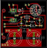
I wish the documents supplied by Counterpoint included a PCB layout so I can compare to the original.
I do have a couple changes. Reduce the first capacitor size to 20 uF or there abouts. Your rectifier will thank you. Install a 1uF or smaller film cap as a bypass across your first cap. HF noise now gone. 😉 A small series resistance might be helpful as well (into the first cap).
What you would have accomplished is to reduce the peak currents in the rectifier tube and first capacitor. It would be nice to do the same thing for your main heater circuit. That would keep those HF bursts out of the rest of the world. Just add a little series resistance. The regulator temperature would then drop a little. 😀
-Chris
Hi Chris (Anatech)
I experienced something really special last week.
The only grounded gear in my system is the preamp (SA5.1) . At least I thought it was grounded until I realized that the swich was lifting the ground on the preamp. I placed the swich to on position so the system was totally grounded.
When grounded, the system was loosing all the soundstage, mids became hard, the sound became harsh. Why ???
My system has a dedicated line. 120 VAC is feeding a 5KVA transformer so the secondary is set at 60-0-60 . The secondary centertap is grounded. There’s about 25 feet of 10 guage shielded in a copper jacket that goes from the 5KVA transformer to the outlets. The shield is actually the GND conductor.
After this awful sound when the system is grounded, I suspect that when the preamp is grounded, the copper shield coming from the transformer in my dedicated line is acting like an antenna so RF is coming in the system by this shield.
The only solution i’m thinking is placing the ground (with a rod in the soil) near the outlets so the long 25 feet wire will not travel RF in it.
What do you think about this situation ?
Thanks
Marc
Hi Chris and Marc,
Chris:
I could place a resistor before the first PSU filter cap (have room on the trace from V8. I would guess this would also need to be 5W as the 500 ohm is... and what, another 500 ohms? I only left the first filtercap at 100uf because that is stock. I'm trying to decide how to best allow for use of any cap/size (both electrical and physical) that you can fit in there.
I have mixed thoughts regarding bypass caps... on a thread on DIY Hifi, they somewhat have shown thru measurements that they can be a bad thing. That coupled with the fact that the HF performance of good electrolytics is now much better than previous caps, sometimes verging on the performance of a good film cap. I guess putting pads in for them is not a bad idea.
Marc:
Do you still have the shield on the umbilical cable between the PSU and the pre? I've never really listened to the float position versus ground in mine other than to see what its effects on noise were (never any change). I would definitely not do a seperate ground rod... that is asking for trouble from an AC household wiring perspective because of the potential differences between it and the ground at the service entrance... take a look at threads on the Audio Asylum (and quite likely here) for why.
Just my $0.02
Chris (Pars)
Yes the shield is there between the PS and Pre. It doesn't do anything about noise reduction.
Only the dedicated outlet for the audio would have a separate ground rod. The shield would not be grounded in the breaker box.
Another of my friends tried to unground his system with cheater plugs. He concluded that the sound is better with his system ungrounded.
Only the dedicated outlet for the audio would have a separate ground rod. The shield would not be grounded in the breaker box.
Another of my friends tried to unground his system with cheater plugs. He concluded that the sound is better with his system ungrounded.
Hi Marc,
A "tech" ground is a seriously bad idea. Abandon it.
You may have circulating ground currents with your pre grounded, so use the ground lift. That is what it's for.
-Chris
A "tech" ground is a seriously bad idea. Abandon it.
You may have circulating ground currents with your pre grounded, so use the ground lift. That is what it's for.
-Chris
Hi Chris,
Someone is smoking something. Electrolytics have inductance and DA issues that we can't get around these days. You just got finished damping the system with resistance, so what you read does not directly apply here. The only true statements are "that the HF performance of good electrolytics is now much better than previous caps" and "they can be a bad thing". Any misapplied technique may make things worse. What you need to do is try it and not to listen so much to theory guys. We are talking about real world components on a real circuit board with real current flowing through them.
Do not forget. You have a voltage regulator that will be very good at getting rid of ripple. It does not perform as well at the higher frequencies. We are trying to extend your rectifier life and reduce the current peaks that cause noise. Those are achievable goals.
-Chris
The design is broken, stock. 😉 Read a tube manual and look up your rectifier. Real designers do not exceed the ratings on components.I only left the first filtercap at 100uf because that is stock.
Nope. Design for a 1W or 2W part. Keep the dissipation to 1/4 this or lower. You are only trying to take the edge off the current spikes. You will notice that the voltage will drop quickly when inserting a resistor here. Figure on the peak currents.I would guess this would also need to be 5W as the 500 ohm is... and what, another 500 ohms?
No way!I have mixed thoughts regarding bypass caps... on a thread on DIY Hifi, they somewhat have shown thru measurements that they can be a bad thing. That coupled with the fact that the HF performance of good electrolytics is now much better than previous caps, sometimes verging on the performance of a good film cap.
Someone is smoking something. Electrolytics have inductance and DA issues that we can't get around these days. You just got finished damping the system with resistance, so what you read does not directly apply here. The only true statements are "that the HF performance of good electrolytics is now much better than previous caps" and "they can be a bad thing". Any misapplied technique may make things worse. What you need to do is try it and not to listen so much to theory guys. We are talking about real world components on a real circuit board with real current flowing through them.
Do not forget. You have a voltage regulator that will be very good at getting rid of ripple. It does not perform as well at the higher frequencies. We are trying to extend your rectifier life and reduce the current peaks that cause noise. Those are achievable goals.
-Chris
If there was more place available in the SA5.1 PS, I would use a choke to replace the 500 ohm resistor. Even best sould be a choke input after the tube rectifier so the 100uF would not bother it at at startup.
I will probably try it for hearing the results.
Marc
I will probably try it for hearing the results.
Marc
Hi Marc,
My point is very simple. There is no reason on earth why the first cap has to be 100uF. It's way outside the spec for even a 5U4! So why allow that to continue? You have the power to fix it (it is an error).
-Chris
My point is very simple. There is no reason on earth why the first cap has to be 100uF. It's way outside the spec for even a 5U4! So why allow that to continue? You have the power to fix it (it is an error).
-Chris
Hi Chris
I agree with you about using the proper capacitance value after the rectifier. My goal with the choke was to clean more the ripple and RF
Many years ago, I builded a Curcio Daniel which had a floating LM317 with Buffers for each tube
(à la Audio Research) .
When I added a choke after the rectifiers, the sound was way better. The regulator in the Curcio was better than the Sa5 reg about ripple but not about sound quality.
- Home
- Amplifiers
- Tubes / Valves
- Counterpoint SA 5.1