Hi Marc,
With the heater current running through the cable, don't worry about shielding it. 🙄 If you want to keep noise down, run the heater lines in a different cable than the HT lines. At least by shielding the cable as it sits, you keep the noise out of other gear.
Do not use a 6BW4!!!!!!!!!!!!!!!!!!!!!!!!!! It has an even lower current rating. If you want, put a resistor in series for a higher voltage drop. According to M.E., that should sound more pure. Where does this garbage come from! I have done these mods. I know what is going on. Don't do it.
The 1.6 mA current regulator diode is more quiet than a resistor. Give me a break!! If you replace the diode with a resistor it will be more noisy. Don't do it. Marc, if you think your preamp is quiet now, install the resistor back in there.
Honestly Marc, approach this with the proper knowledge and your preamp will perform better. Follow M.E. and you'll be doing endless upgrades and never getting the performance you could have.
-Chris
With the heater current running through the cable, don't worry about shielding it. 🙄 If you want to keep noise down, run the heater lines in a different cable than the HT lines. At least by shielding the cable as it sits, you keep the noise out of other gear.
Do not use a 6BW4!!!!!!!!!!!!!!!!!!!!!!!!!! It has an even lower current rating. If you want, put a resistor in series for a higher voltage drop. According to M.E., that should sound more pure.
Where does this garbage come from! I have done these mods. I know what is going on. Don't do it.The 1.6 mA current regulator diode is more quiet than a resistor. Give me a break!! If you replace the diode with a resistor it will be more noisy. Don't do it. Marc, if you think your preamp is quiet now, install the resistor back in there.
Honestly Marc, approach this with the proper knowledge and your preamp will perform better. Follow M.E. and you'll be doing endless upgrades and never getting the performance you could have.
-Chris
anatech said:Hi Marc,
With the heater current running through the cable, don't worry about shielding it. 🙄 If you want to keep noise down, run the heater lines in a different cable than the HT lines. At least by shielding the cable as it sits, you keep the noise out of other gear.
Do not use a 6BW4!!!!!!!!!!!!!!!!!!!!!!!!!! It has an even lower current rating. If you want, put a resistor in series for a higher voltage drop. According to M.E., that should sound more pure.
The 1.6 mA current regulator diode is more quiet than a resistor. Give me a break!! If you replace the diode with a resistor it will be more noisy. Don't do it. Marc, if you think your preamp is quiet now, install the resistor back in there.
Honestly Marc, approach this with the proper knowledge and your preamp will perform better. Follow M.E. and you'll be doing endless upgrades and never getting the performance you could have.
-Chris
Hi Chris
I tried the 6BW4 and didn't like the sound it gave. The sound was too bright. I knew that the rating was lower than the 6CA4. I'm staying with Telefunken 6V4 which gives a sound that please me.
Mills resistors are what I use in many mods I do. My Single ended 45 is made with them. They are not noisy and don't give the cold sound many MF resistors do. For my taste old CC sounds best but they're not stable and noisy in preamps.
About caps, the Dynamicaps give me a sound that I would call a mix of oil cap with the treble of a good polystyrene cap. I saw in a post that you recomment Solen. About my taste, I really don't like them. The wondercaps are better.
I placed a resistor at the place of the current source because I didn't have any current source on hand. I don't pretend that it is better. I promise you that i'll order a current source to replace the resistor. Sometimes, i'm lazy and if things works, they stay like they works.
I'm really not trying to follow ME.
Shielding the cable was not to run the noise down. It is doing the same thing a good Shielded powercord do (I've also done it on the SA5.1) Unshielded cords acts like antennas and RE comes in. I don't want to convert you about the benifits of a good power cord can do. I was sceptic about them but not now, specially on digital gear
P.s. The M5 is shelved because it was beginning to make me crazy. I will have to find a 2SK146 for it. My Electrocompaniet AWII makes me forget the fastidious work I have to do in it.
Regards
Marc
legarem said:Hi Chris
I remember you
I will look at the resistor value tonight.
The cable shield is grounded on preamp and PS cases
Marc
Hi Marc,
I would think that grounding the shield at both ends would override the Ground/Float switch on the PSU... you would no longer be able to float it. The switch ties pin 1 in the cable to the PSU chassis ground when in Ground position... pin 1 is the one connected to the chassis in the preamp itself. I never use the Float position, but ya never know.
Also, what sizes of Dynamicaps did you use? If I could find these for a reasonable price (like when Soniccraft had their 20% off sale), I may start replacing the coupling caps in mine. Mine has (stock) 8uf and 3uf Wondercaps in it.
Speaking of the powercord, I need to change the one on mine. I'm measuring pretty high resistance on at least the ground wire from the transformer lug to the ground pin on the plug (~200 mOhms, 4 wire measurement). I'd always had trouble getting the pre board ground to ground pin down below 0.5 ohms as the service manual states. I was considering putting an IEC in. I just typically use something like the Crump's Asylum cord (Belden 19364, Pass and Seymour 5266X plug and a Schurter IEC connector). Can't really say that I'm a believer in PCs though, and am more apt to believe that they expose weaknesses in the PSU design and CMRR than anything else.
Chris
Hi Chris
Isn't the float swich lift off the ground from the power cord to the wall ?
Anyway, the only grounded gear in my system is the preamp. If you connect more than one gnd to the wall outlets, you can create ground loops. The 120VAC that feeds my system is balanced 120VAC (60-0-60) made with a 5 kva transformer. The center tap goes to a rod in the soil. I will try to find the parts list I bought from partsconnexion to give you the Dynamicaps part #. I remember that I had to take out the shields to do the job.
Marc
Hi Marc,
As far as caps go, I don't really have a strong preference. I probably made the Solen cap reference in response to another much more costly recommendation. I generally don't use metal film type resistors except in the signal path near the beginning of the audio chain.
Why don't you set up a current source using a red LED and a PNP transistor? It will be stable and quiet. That's what I normally do (or NPN depending on where you need it). An MJE350 will give you a 350V rating. Not perfect, but better than the regulator diode.
On power cords. I have to agree with Chris (Pars). I think they may help with a poor supply - possibly. I've never heard a difference myself but I'll defer to those who have.
-Chris
I'm relieved then. Things started to sound a bit scary there! I'm with you on the picking up RF thing. Consider too the HF spikes on the heater lines.I'm really not trying to follow ME.
As far as caps go, I don't really have a strong preference. I probably made the Solen cap reference in response to another much more costly recommendation. I generally don't use metal film type resistors except in the signal path near the beginning of the audio chain.
Why don't you set up a current source using a red LED and a PNP transistor? It will be stable and quiet. That's what I normally do (or NPN depending on where you need it). An MJE350 will give you a 350V rating. Not perfect, but better than the regulator diode.
On power cords. I have to agree with Chris (Pars). I think they may help with a poor supply - possibly. I've never heard a difference myself but I'll defer to those who have.
-Chris
Marc,
The PSU chassis stays grounded irregardless of the float switch setting (a good thing!). The switch controls whether the preamp chassis is tied to ground or not, via pin 1 on the umbilical.
As for the caps, if you had to remove the shields, you probably used fairly large values... 1 or 2uf (maybe bigger) would still fit with the shields.
Chris
Hi Chris,
You want to keep the shields. Larger caps will not help.
One of the problems I've seen are the larger caps picking up noise due to proximity to other signal carrying conductors. It's a very real problem as the S/N ratio goes up. Another problem I've seen (unbelievably) is ventilation issues caused by oversized parts. Typically capacitors.
-Chris
Hi Chris (and Marc),
Any comments on this from a couple of posts back:
'--------------------------------------------------------------
Speaking of the powercord, I need to change the one on mine. I'm measuring pretty high resistance on at least the ground wire from the transformer lug to the ground pin on the plug (~200 mOhms, 4 wire measurement). I'd always had trouble getting the pre board ground to ground pin down below 0.5 ohms as the service manual states. I was considering putting an IEC in.
'---------------------------------------------------------------
I should note on the powercord resistance measurement: it seems to be quite difficult to get good contact on the ground pin. Measurments are sometimes pushing 0.5 ohms (4 wire). I may just put a new connector on the cable first so see if it is the cable itself or the connector (molded stock). I have not checked the hot and neutral resistance. 4 wire measurements using an HP 3468B bench meter.
Chris (Pars)
Hi Chris,
Sorry, your 200 mohm measurement was below 0.5 ohms.
If your power cord is at all intermittent with the ground connection, replace it. I like IEC sockets and cords. They make my life easier. If you can install a socket without too much trouble, go ahead and do it.
HP makes excellent test gear. I use a 34401A.
-Chris
Hi Chris,
That was 200-400 mOhms from the transformer lug, not from the preamp board connection. From there, it will go down to about 0.5 ohms, but can go up as high as 1 ohm. As best I can tell, the power cord is not intermittent, but good contact on the ground lug of the connector is a problem. Measuring a power cord I built from Belden 19364 which is twice is long, the ground conductor measures < 10 mOhms.
I think I'll put the IEC in after I have fired this thing up and seen what the performance is like (one problem at a time).
Chris (Pars)
Hi Chris,
Clean the coating off the transformer lug and case. That is a common problem in some of his other units. Your umbilical may be tired too.
One problem at a time. Definitely.
-Chris
Clean the coating off the transformer lug and case. That is a common problem in some of his other units. Your umbilical may be tired too.
One problem at a time. Definitely.
-Chris
Hi Chris (and Marc),
I have been spending some time before I fire this thing up after the PSU work ohming the PSU out to see what all changed from the SA5 schematic.
I was curious as to how the tube heaters on all the time feature was implemented, and found that the power switch now controls only the heater circuit for V8. This means that the transformer is always on... I guess until the V8 heater goes, the tube won't fire up (excuse my tube noobiness)? But since there obviously isn't room for multiple transformers that that is about the only way you could do it without putting in multiple switches.
Marc:
Have you got any pics of your pre? I would be particularly interested in seeing how you implemented the Black Gates in the PSU. Also, if you want a .pdf of sch. you mailed to me back when, let me know.
Chris
Hi Chris,
I disagree with keeping the heaters at full temperature with no B+. I would much rather see the power switch control the primary power to the transformer. You could then lose the heater connection in the umbilical and turn it on and off via the power supply unit.
-Chris
Yes, that's how they do it. They could not keep the heaters hot any other way unless they did use another power transformer.This means that the transformer is always on... I guess until the V8 heater goes, the tube won't fire up (excuse my tube noobiness)? But since there obviously isn't room for multiple transformers that that is about the only way you could do it without putting in multiple switches.
I disagree with keeping the heaters at full temperature with no B+. I would much rather see the power switch control the primary power to the transformer. You could then lose the heater connection in the umbilical and turn it on and off via the power supply unit.
-Chris
Hi Chris,
Finally got the guts (and time) to fire this thing up. Nothing exploded or started on fire... seems to be working fine as far as voltages go. I have not Q-doped the front of the PSU board yet. I turned off the lights and looked around and could see no signs of any arcing.
I still have the 2x 49.9K resistors in for R140 / R51. I tried out both of the new 6JC6A tubes that I got. Both drop more voltage across the zener (~80V for the Amperex and 72V for the Raytheon), so I guess the RCA that I had in there (with the 45V drop) must be the weak tube of the lot, and I'll need to revisit resistor values. The output voltage is a bit low (224V) and the voltage on C51 is also lower ~270 something versus 309 before. Voltage dropped across R140 is about 72V, giving ~1.45mA. Can't seem to get to 1.6mA with either of the 1n5303s that I have... I might try one of the CR160s I have, but both of those measured lower than the 1n5303s when I tested them with a 9V battery.
I will go back to the 100K in R51 and 1K in R140 and see how things look. Its looking like the stock 107K in R51 may have been about right for this. I assume that the target of 45V is to place the CRD midpoint in its operating range?
I'll have to try listening to it and see what the hum etc. situation is.
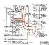
Also, can you explain to me what is going on with the outlined portion of the attached pic? I can't understand why you would want to feed in the AC heater voltage into the DC HV regulation section...
Chris (Pars)
Finally got the guts (and time) to fire this thing up. Nothing exploded or started on fire... seems to be working fine as far as voltages go. I have not Q-doped the front of the PSU board yet. I turned off the lights and looked around and could see no signs of any arcing.
I still have the 2x 49.9K resistors in for R140 / R51. I tried out both of the new 6JC6A tubes that I got. Both drop more voltage across the zener (~80V for the Amperex and 72V for the Raytheon), so I guess the RCA that I had in there (with the 45V drop) must be the weak tube of the lot, and I'll need to revisit resistor values. The output voltage is a bit low (224V) and the voltage on C51 is also lower ~270 something versus 309 before. Voltage dropped across R140 is about 72V, giving ~1.45mA. Can't seem to get to 1.6mA with either of the 1n5303s that I have... I might try one of the CR160s I have, but both of those measured lower than the 1n5303s when I tested them with a 9V battery.
I will go back to the 100K in R51 and 1K in R140 and see how things look. Its looking like the stock 107K in R51 may have been about right for this. I assume that the target of 45V is to place the CRD midpoint in its operating range?
I'll have to try listening to it and see what the hum etc. situation is.
Also, can you explain to me what is going on with the outlined portion of the attached pic? I can't understand why you would want to feed in the AC heater voltage into the DC HV regulation section...
Chris (Pars)
Attachments
Hi Chris,
They are biasing the heater for the pass tube to B+ so they don't exceed the heater to cathode voltage.
Don't worry too much about the exact output voltage or diode current. They had wide ranges in tolerance so don't loose any sleep over it. It would be nice to get your B+ voltage up a little higher.
Your output voltage is set by the grid to cathode voltage on the 6JC6. So the voltage on the cathode is your reference voltage. The divider formed by R57 and R58 samples the output voltage and applies it to the grid. The tube then compares the two voltages and changes it's conduction to stay in it's "happy steady state". This will change the voltage on the plate and the amount of voltage on the grid of the pass tube 6GC5.
-Chris
Hi Chris,anatech said:It would be nice to get your B+ voltage up a little higher.
pass tube 6GC5.
Yes, I had replaced R57 a couple of years ago... my B+ at that time was 260 or maybe a tad more. Guessing that this area of the circuit is more feedback than feeding the B+, I figured that increasing R57 might drop the CRD voltage into place (?), so I decided to raise it. I had around 43.2K in there (47.5K || 475K), so I removed the 475K. With the Raytheon tube in (CRD voltage had been around 70 previously), the voltage across the CRD is now about perfect (42-45 Vdc). B+ is about 236-238.
I hooked it into my system today just to check the hum level, etc. Getting better (didn't hear any of the previous random and seldom pops). Hopefully when I get the tubes biased the hum will pretty much be gone... if you could comment on the sonic effects that you have heard in your experience due to bias being off (or way off), I'd appreciate it.
I got ahold of a PC and got a firewire card and the M-Audio Firewire Audiophile box to run RMAA for biasing (slow, but the only thing i have). For biasing the phono section, do I need to build that pre-equalization circuit shown in the service manual? Or are there workarounds?
Thanks,
Chris
Hi Chris,
Your random pops are either tube issues, or the HV rectifier arcing I would think. Get that board lacquered, carving burned PCB out is a pain in the butt. Your HV regulator seems to be happy now. 10 V is nothing to worry about.
I use an audio oscillator, so I don't worry about a reverse phono EQ circuit. I've been thinking about building one for years. What does that tell you? 😉
The biasing should not affect hum level. It will affect distortion levels and order. Hang a scope on your heater supply and make sure the filters are okay. Don't be too surprised if they aren't.
-Chris
anatech said:Hi Chris,
Your random pops are either tube issues, or the HV rectifier arcing I would think. Get that board lacquered, carving burned PCB out is a pain in the butt. Your HV regulator seems to be happy now. 10 V is nothing to worry about.
The tube socket side is coated. I haven't done the solder side yet. The 10V comment... the B+ should be higher?
Originally posted by anatech
I use an audio oscillator, so I don't worry about a reverse phono EQ circuit. I've been thinking about building one for years. What does that tell you? 😉
???
Originally posted by anatech
The biasing should not affect hum level. It will affect distortion levels and order. Hang a scope on your heater supply and make sure the filters are okay. Don't be too surprised if they aren't.
-Chris
What am I looking for with the scope? Excess ripple? By filters you mean the caps? Any other causes of hum (bad grounds?, wire routing?, other?).
Thanks,
Chris (Pars)
Hi Chris,
-Chris
It's a pain, but do it.I haven't done the solder side yet.
Worst case, 244 - 236 is 8 V. 10 V is close enough even. In other words, don't worry about it.The 10V comment... the B+ should be higher?
The need hasn't been high enough to build one. Then it needs to be good enough so as not to introduce it's own errors. 4:1 at the very least in accuracy. Not really worth it unless you are designing phono stages. So I am still considering it.
Yes. The regulator may "drop out" on the troughs and allow ripple through. Your meter gives you only the roughest of clues as to what is going on.What am I looking for with the scope? Excess ripple?
Sure, anything is possible. Eliminate the possible circuit causes first.Any other causes of hum (bad grounds?, wire routing?, other?).
-Chris
Hi Chris,
Regarding biasing the phone section: I take it from your answer that you just inject a sine wave (1KHz) and adjust for the lowest distortion you can get? Or perhaps I am missing something...
Regarding the heater supply, I threw a scope on it (and a DMM). Ripple is low (somewhat distorted sine wave with no spikes that I could see), 11mVrms on the meter, and looked about that on the scope (x10 probe, 50mV/div, approx. .2-.4 div PP), frequency was 1.6x div @ 5ms/div, so 120Hz.
General question: if I decide to look at the ripple of the B+ on a scope, can I ground the probe since it is not a floating device? Or would I really want to use a differential probe for this? (Sorry, been 20 years plus since I worked as a tech in the semicon industry, and they weren't my scopes then 😀).
Regarding the popping I had mentioned earlier... when I listened to this the other day it seemed to be gone. Maybe I'm chasing my tail here... my speakers have a 92dB sensitivity... power amp is an Odyssey Stratos (150 W/ch). I can hear a hum/very light hiss at ~1' from the tweeter. With my Gilmore Dynamic headphone amp (DIY), which can also double as a pre, it is dead quiet.
At full volume on the high gain setting my wife could not hear it seated ~10' away. Will a tube preamp ever give you dead quiet that close to the tweeter or am I expecting too much? Maybe I'll borrow my brother's Audible Illusions and see how it is.
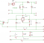
Also, I attached what I came up with for a PSU schematic for an SA5.1 from ohming mine out.
Chris (Pars)
Regarding biasing the phone section: I take it from your answer that you just inject a sine wave (1KHz) and adjust for the lowest distortion you can get? Or perhaps I am missing something...
Regarding the heater supply, I threw a scope on it (and a DMM). Ripple is low (somewhat distorted sine wave with no spikes that I could see), 11mVrms on the meter, and looked about that on the scope (x10 probe, 50mV/div, approx. .2-.4 div PP), frequency was 1.6x div @ 5ms/div, so 120Hz.
General question: if I decide to look at the ripple of the B+ on a scope, can I ground the probe since it is not a floating device? Or would I really want to use a differential probe for this? (Sorry, been 20 years plus since I worked as a tech in the semicon industry, and they weren't my scopes then 😀).
Regarding the popping I had mentioned earlier... when I listened to this the other day it seemed to be gone. Maybe I'm chasing my tail here... my speakers have a 92dB sensitivity... power amp is an Odyssey Stratos (150 W/ch). I can hear a hum/very light hiss at ~1' from the tweeter. With my Gilmore Dynamic headphone amp (DIY), which can also double as a pre, it is dead quiet.
At full volume on the high gain setting my wife could not hear it seated ~10' away. Will a tube preamp ever give you dead quiet that close to the tweeter or am I expecting too much? Maybe I'll borrow my brother's Audible Illusions and see how it is.
Also, I attached what I came up with for a PSU schematic for an SA5.1 from ohming mine out.
Chris (Pars)
Attachments
- Home
- Amplifiers
- Tubes / Valves
- Counterpoint SA 5.1