Hi Chris,
Yeah, I seem to be fresh out of 75Ks... will have to see what I have laying about that will get close or slightly above for starters. Just wanted to check to see what you have seen in your poking around and wasn't sure what the CRD would behave like as I changed things (I know, just try it, right ).
).
Thanks as always for the reply,
Chris (Pars)
Yeah, I seem to be fresh out of 75Ks... will have to see what I have laying about that will get close or slightly above for starters. Just wanted to check to see what you have seen in your poking around and wasn't sure what the CRD would behave like as I changed things (I know, just try it, right
).Thanks as always for the reply,
Chris (Pars)
Hi Chris,
Start with 82 K then. You can pad it to correct the voltage if needed.
If you measure the voltage across the existing resistor you can figure out the current. Expect the current to rise slightly with more voltage across the diode. From your measurements you can then calculate what should be close to the correct value. It is simply the current X the new resistance that would give about 45 VDC across the diode.
-Chris
Hi Chris,anatech said:Hi Chris,
Start with 82 K then. You can pad it to correct the voltage if needed.
If you measure the voltage across the existing resistor you can figure out the current. Expect the current to rise slightly with more voltage across the diode. From your measurements you can then calculate what should be close to the correct value. It is simply the current X the new resistance that would give about 45 VDC across the diode.
-Chris
That is the part I don't understand about this circuit... what is the effective resistance of the CRD? I can calculate what the current thru any resistor I put in for R51 is and how much voltage will be dropped across R51, but what will be across the diode? Seems like I'm missing something here, as one end of R51 (at V6) is supposed to be ~244 Vdc.
Chris (Pars)
Hi Chris,
The CRD has a very high impedance. It's effective resistance in probably a meg ohm or so. It's really a fet transistor (closest thing). All you have to know about it is that it is a little temperature sensitive and it passes a constant current (more or less) across it's voltage operating range. The tube operates as a variable resistance and the voltage reference tube simply drops a constant voltage. The current diode prevents shifts due to the 5651's "bulk resistance" (operates close to the same point on it's curve).
The series resistor will drop a voltage depending on the current passing through it. So you take your total supply voltage (a variable), subtract the zener voltage (the voltage reference) and the 45 volts you want across the diode. What is left is what you want across the series resistance (nominal 75 K). Assume that voltage is 68V. A 42.5 K resistor would be required to drop that. You have 1.6 VDC across the other resistor and a 43 K resistor is a standard value. This would then leave you with 0.8 V more drop + 1.6 V, or about 42.6 V. Close enough. It will drift up and down. In this design the average loss required would be on the order of 120 VDC, hence the 75 K resistor.
Now, we've made our reference voltage stable, the tube simply amplifies the difference between it's reference on the cathode and the sampled voltage on it's grid. It adjusts it's effective resistance to drop more or less current (and therefore the voltage across it) as required to drive the pass tube (6GC5) enough so that it changes it's effective resistance to maintain a constant voltage out.
One thing that may help you is to realize that a constant 1.6 mA is flowing through CR1, R51, V5 and V6. The voltage dropped by any one device occurs because the resistance has changed. The total of the voltage drops must equal the total supply voltage at any one instant, therefore the only device that can have the voltage drop change because of a change in V5 (unintentional = device fault) or V6 (intentional) is CR1. You want to have about 45 VDC across it so that the voltage can vary across it and it will still be in a linear range. If the voltage increases too high, D3 will conduct and the current is uncontrolled (very bad). If the voltage drops too low, the CRD will cease to regulate (drops out) and the current in that series string will drop. The output voltage will then fall as the circuit no longer functions properly.
-Chris
Hi Chris,
Thanks, that was most helpful. I guess I could read up on tubes more and see what is going on here WRT to V5/V6 and V7.
Chris (Pars)
Thanks, that was most helpful. I guess I could read up on tubes more and see what is going on here WRT to V5/V6 and V7.
Chris (Pars)
Hi Chris,
I started doing some testing using an R51 of 84K (what I had around, a couple of 43.3K resistors). Here is what I got:
B+: 422V
R51: 84K
Vr51: 121V (ranges from ~119V to 122Vdc)
Vd3: 70V-71Vdc
Ir51: 1.43mA
Vc51: 349Vdc
meter: Protek 608
The voltage across D3 (and the CRD) hits the zener voltage at about 91.3V when the voltages are coming up at power up, and again when either V5 or V6 (can't recall which one it is fires), then drops, once as low as 60V. This seems to climb as the unit has been on, and normally goes up to around 78-80Vdc. The 119V reading corresponds to a reading across D3 of ~80Vdc. The output voltage (C55) seemed fairly steady at around 236Vdc, but I didn't spend much time looking at it (I had changed R57 awhile back from around 50K to 42K to drop a high output voltage of 260Vdc... I'll probably have to redo this once I have this part right).
Something doesn't seem right here, as the CRD current seems to have decreased a bit, and the voltage across the zener is too high and varies more than I would think it should. I changed back to the previous C51 (Nichicon VX 22uf 450V, had put in BlackGate VK 22uf 350V) and retested, but same behavior (the 350V cap had been exposed briefly to ~420V when the zener was fried).
Could tube condition be contributing to this? I do have another set of tubes, condition unknown. The current tubes are pulls I believe that I got from Dennis Boyle at Chimera Labs probably around 2002-2003 timeframe.
I guess I will need to go back up to around 92-100K range and try again. I checked a second CRD and results were the same also (I got tired of cleaning out one of the holes for these, so put in some SIP sockets for the CRD).
Thanks,
Chris
Hi Chris,
Put the original R51 resistors (107K) in, problem still there (Vd3 of around 26Vdc). Replaced V5 and V6 with the old ones (the 6JC6A is marked Counterpoint, so probably the original). Voltages came up to 50-60Vdc range (starts around 50, creeps up as it warms up). It appears that the 6JC6A is the bad one. I'll see what I can find around town (Triode Electronics?). If not, any recommendations for good tube sellers?
I'm still concerned about the voltage creeping up and not staying stable. Is this normal? I took a look at B+ and it stayed stable ~434Vdc.
Thanks,
Chris (Pars)
Attachments
Hi Chris,
I'm not feeling that good today. I'll try and have a look at everything and respond tomorrow. It's now 10:34 PM by my time and I'm dead tired.
-Chris
I'm not feeling that good today. I'll try and have a look at everything and respond tomorrow. It's now 10:34 PM by my time and I'm dead tired.
-Chris
Hi Chris,
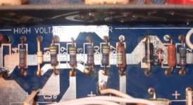
Didn't work on it much tonight. Called Triode, they didn't have any 6JC6As in stock, so I bought a pair off of Ebay (http://cgi.ebay.com/ws/eBayISAPI.dll?ViewItem&item=230046953344&sspagename=ADME:B:AAQ:US:1... I wound up taking the Amperex and the Raytheon 2nd from the right... don't know about brands for this tube).
I went back to my newer tube (the one giving 24-26V drop across the zener) and put a 100K in R51. Looks good (from 40-50Vdc, though I'm starting to mistrust my Mueller leads as I move them around the voltage changes). I'll hopefully get a better idea of which tube is to be trusted when I get the others.
Had a thought regarding the whole setup: since I have the R140(1K) in front of the CCS, and 100K R51 after it, the cap voltage (C51 is ~380V... too high for the BlackGate and hard to find a 10uf film for). The thought struck me that as long as the resistance thru that leg stays the same, why couldn't I swap R140 and R51? It would put the cap voltage down around 250 or so, same current (I think). From what I understand of CCS's, they like driving more of a short than a high impedence anyhow? Or if V6 won't like that, then maybe split the 100K over R140/R51? I didn't try any of this yet cuz sounded better.
Thanks,
Chris (Pars)
Didn't work on it much tonight. Called Triode, they didn't have any 6JC6As in stock, so I bought a pair off of Ebay (http://cgi.ebay.com/ws/eBayISAPI.dll?ViewItem&item=230046953344&sspagename=ADME:B:AAQ:US:1... I wound up taking the Amperex and the Raytheon 2nd from the right... don't know about brands for this tube).
I went back to my newer tube (the one giving 24-26V drop across the zener) and put a 100K in R51. Looks good (from 40-50Vdc, though I'm starting to mistrust my Mueller leads as I move them around the voltage changes). I'll hopefully get a better idea of which tube is to be trusted when I get the others.
Had a thought regarding the whole setup: since I have the R140(1K) in front of the CCS, and 100K R51 after it, the cap voltage (C51 is ~380V... too high for the BlackGate and hard to find a 10uf film for). The thought struck me that as long as the resistance thru that leg stays the same, why couldn't I swap R140 and R51? It would put the cap voltage down around 250 or so, same current (I think). From what I understand of CCS's, they like driving more of a short than a high impedence anyhow? Or if V6 won't like that, then maybe split the 100K over R140/R51? I didn't try any of this yet cuz
sounded better.Thanks,
Chris (Pars)
Hi Chris,
I'm going to print this stuff out and go over the schematic. That way I can collect my thoughts and give you a proper answer. Sorry for the delay here. It's been a rough few days for me.
-Chris
I'm going to print this stuff out and go over the schematic. That way I can collect my thoughts and give you a proper answer. Sorry for the delay here. It's been a rough few days for me.
-Chris
Hi Chris,
Don't swap those resistors. Just bypass a normal electrolytic with a smaller film type if you want. You don't want the capacitance right on the plate of V6, even with a 1K resistor in series.
Don't forget that the B+ to each circuit is filtered again. An expensive film cap for C51 would be wasted.
A true current source doesn't care about it's load unless the load goes open (then voltage compliance comes into play).
So your voltages look good so far, excellent. I still will go over what you have posted before. Short your leads and measure the resistance. Move the leads while watching the resistance reading. Breakage wil normally occur near the connection to an end of a lead.
-Chris
Hi Chris,
Hope you are feeling better. My other thought had been to split the ~100K across R140 / R51.
I have a pair of 50K Dales that I could use, or something like that.
Wife has me doing other stuff today 😱
Chris (Pars)
Hope you are feeling better. My other thought had been to split the ~100K across R140 / R51.
I have a pair of 50K Dales that I could use, or something like that.
Wife has me doing other stuff today 😱
Chris (Pars)
Hi Chris,
In a series circuit, the total voltage drop between your B+ point and V6 plate doesn't matter. The existance of your capacitor will affect how fast the circuit can react to correct the voltage output of the regulator. I would not change this if I were you. Just use a 10 uF 450V capacitor for C51. You should have around 270 VDC across that capacitor once the regulator has settled down from start up.
You will find the voltage across CR1 will vary a lot with variations in the supply. The voltage drop will vary directly with the raw B+ supply, this is normal. Remember, this part is intended to accept these voltage variations and maintain a constant current. Every other part in the chain is sensitive to the voltage across it to a much greater degree.
It sounds as if you have it working properly. Just install a suitable capacitor for C51.
-Chris
Hi Chris,anatech said:Hi Chris,
In a series circuit, the total voltage drop between your B+ point and V6 plate doesn't matter. The existance of your capacitor will affect how fast the circuit can react to correct the voltage output of the regulator. I would not change this if I were you. Just use a 10 uF 450V capacitor for C51. You should have around 270 VDC across that capacitor once the regulator has settled down from start up.
You will find the voltage across CR1 will vary a lot with variations in the supply. The voltage drop will vary directly with the raw B+ supply, this is normal. Remember, this part is intended to accept these voltage variations and maintain a constant current. Every other part in the chain is sensitive to the voltage across it to a much greater degree.
It sounds as if you have it working properly. Just install a suitable capacitor for C51.
-Chris
There is actually about 370-380Vdc across that capacitor (I assume the 270 in your post was a typo). The schematic shows 355 at that point. If I can come up with a 4.7-10uf 400V box film cap like a Wima or Rifa or something like that for this position, that is what I would think I would use. I have a couple of BC MKP383 X2 caps in 2.2uf which are rated at 275Vac (datasheet says 630Vdc) that I might toss in there (1 of them) if you think that is enough capacitance at this point. Digikey also has some AVX polypropylene in a 10uf 525Vdc that would work and fit (a bit pricey at $10 a pop, but the box style would be easier to fit than a Solen or something like that, smaller too).
C50 also has me a bit concerned (Wima MKP10 1uf 400Vdc with 434 Vdc across it... he does seem to like running caps overvoltage). C56 was the one I replaced (was an 8uf 210V Wondercap, replaced with a 1uf 450V Auricap). It still measured at 8uf according to my meter, so must not have minded the 260Vdc too much.
Yeah its getting close... might actually have to try listening to it one of these days and see what things sound like. And bias the tubes...
Chris (Pars)
Hi Chris,
-Chris
It was a typo sort of. I figured out what you should have at the plate of V6 and was wrong anyway. You would read the regulated output voltage less the grid - cathode voltage there.There is actually about 370-380Vdc across that capacitor (I assume the 270 in your post was a typo).
Mr Elliot does not do power supplies well. There is normally something wrong somewhere. He also runs those transformers too darn hot. He seems to mess up basic things with regularity.C50 also has me a bit concerned (Wima MKP10 1uf 400Vdc with 434 Vdc across it... he does seem to like running caps overvoltage).
Do that. You only need to install it once.Digikey also has some AVX polypropylene in a 10uf 525Vdc that would work and fit (a bit pricey at $10 a pop, but the box style would be easier to fit than a Solen or something like that, smaller too).
-Chris
anatech said:So your voltages look good so far, excellent. I still will go over what you have posted before. Short your leads and measure the resistance. Move the leads while watching the resistance reading. Breakage wil normally occur near the connection to an end of a lead.
-Chris
Hi Chris,
The problem is the grabbers that these came with, plus the finish on the lead tips themselves. I roughed the points up a bit and cleaned them with deoxit, so they seem to be working better now. The only other pair of leads with enough HV cap. I have don't take attachments, and I'm not going to manually hold leads for this
 . Any recommendation for good test leads at a somewhat reasonable price?
Also, two other questions. Are the pins for the connector for the PSU umbilical available anywhere, in case I decided to redo the internal wiring in the PSU and redo the umbilical itself? The connectors are JAE, and I haven't found alot on them.
Also; knobs for these. One of mine is discolored and I either want to get it refinished, or see if I can find a new one (one of the larger round ones). I know the finish is bead blasted and then anodized (email from M.E.). Any thought or tips?
Thanks again for all your help,
Chris (Pars)
Hi Chris,
My test leads cost me $60 from HP. I am on my second set. At first I thought they were cheap, but after using them for a couple months I found that I preferred them. That's why I replaced them with the same.
If you don't want to spend that much, Pomona and HH Smith make lead sets. Stay completely away from the cheap sets.
The PSU umbilical is something you don't want to play with unless you have to. I have never done this so I'm a poor person to ask about it.
Knobs.
I don't know. The only other suggestion I have is to find something else you like and buy a complete set. I am assuming you will not be buying plastic knobs. 😉
They are going to cost you. Cosmentics. 🙄
-Chris
Hi Chris,
Tried it out today with the 49.9Ks in both R51 / R140. Seems to work fine, although I will probably go back to the 100K / 1K. Voltages looked the same, although I'm not sure that V5 was lit up as bright... not sure why that would be (or it might have been my imagination)... it had 84V at the bottom. Voltage on C51 was 304V, right where I had calculated (I had 309V). I can't see where this change would have any detrimental effects, other than perhaps the RC related to C51? I'm getting ready to order the film caps we discussed to go back to the 100K/1K setup.
I didn't listen to it, but was just checking for hum/noise. The low level hum is still there (pot halfway up, varies with the pot position, same in both channels, 1' from speaker it is fairly audible). This is something I have been trying to get rid of since I have had the preamp. A bit of hiss, some hum, very slight "popping" noise(s) occasionally. All electrolytics in the pre and PSU have been replaced. When working on it this time, I did redo some of the between board joints.
Any thoughts on things to look for? I had replaced the linestage tubes with the 6922EHs, but the phono stage still has some Amperex in it.
Thanks,
Chris (Pars)
Placed order with Digikey. After reading thru the forums a bit, I came across an IXYS CCS (IXCP10M45S) that looks like the perfect replacement for the 1N5303 in the SA5.1.
datasheet
This thing will handle 450 Vdc, so no need for the zener, etc. that is already in this circuit to protect the CRD. From the datasheet it looks like using a ~2K ohm resistor will result in 1.6mA. So I ordered one (they're $1.79, probably cheaper than the existing CRD).
Still need to work on the hum issue I am having per previous post. Will look at the heater circuit since I'm out of other ideas.
- Home
- Amplifiers
- Tubes / Valves
- Counterpoint SA 5.1