35VDC originally (?), but I've got a set of NOS mallory 60VDC 40kuf caps in there right now. I still have about 4-5 milk cartons and several boxes full of caps.....
Hi Ken,
You may be further ahead with the originals. They should be fine with the higher voltage option.
I don't like the peak charging currents and shorter conduction angles associated with larger caps.
-Chris
You may be further ahead with the originals. They should be fine with the higher voltage option.
I don't like the peak charging currents and shorter conduction angles associated with larger caps.
-Chris
R140?
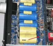
Well, decided to do a little work to m preamp, and wound up toasting a resistor marked R140. This is in the HV reg section, in between the 422V B+ rail and the CRD/Zener setup (it right next R52 on the schematic). This resistor does not appear in my schematic, and I can't read the value on it now (it measures ~100 ohms, but in a previous post on another forum, I had stated that it was 1K). Having doubts before I replace it, so if anyone has this in a schematic and can tell me what the value is, I'd appreciate it.
I already figured out how I caused it
Thanks,
Chris
Chris,
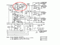
I don't see an R140. I do see R51 which is normally around 75K. It is between V6 plate, R53 and the junction of C50, CR1 and D3. Adjust it's value to get around 45 VDC across CR1 and D3.
That's all I can think of right now.
-Chris
I don't see an R140. I do see R51 which is normally around 75K. It is between V6 plate, R53 and the junction of C50, CR1 and D3. Adjust it's value to get around 45 VDC across CR1 and D3.
That's all I can think of right now.
-Chris
Already have an R51, and yeah, it is around 75K IIRC. This is a silkscreened/marked official resistor, second resistor board from the right in that row by the vertical board. Must be part of the 5.1 upgrade, as my schematics for the most part are 5.
Attachments
Hi Chris,
Send me the image please.
I may have to see another to amend my notes and give you your answer.
When they were going down, I convinced an internal friend to send me a package of all manuals. The early product was a mystery still sometimes.
-Chris
Send me the image please.
I may have to see another to amend my notes and give you your answer.
That's how the "official" docs are. The early docs are substandard, the newer manuals were terribly inconvenient for an external shop. Their policy was service in the 'States was by Counterpoint only. For other countries, they set up depots and I always had to fight for parts and documentation.Must be part of the 5.1 upgrade, as my schematics for the most part are 5.
When they were going down, I convinced an internal friend to send me a package of all manuals. The early product was a mystery still sometimes.
-Chris
What image? I ohmed the SA5.1 version that I drew in the previous post out from what is actually there. Mine is an SA5.1. SInce the board changed some from the SA5 to the SA5.1, I would guess that all SA5.1s have this. Here is a pic I had of someone else's SA5.1 showing the location of R140.anatech said:Hi Chris,
Send me the image please.
Originally posted by anatech I may have to see another to amend my notes and give you your answer.
That's how the "official" docs are. The early docs are substandard, the newer manuals were terribly inconvenient for an external shop. Their policy was service in the 'States was by Counterpoint only. For other countries, they set up depots and I always had to fight for parts and documentation.
When they were going down, I convinced an internal friend to send me a package of all manuals. The early product was a mystery still sometimes.
-Chris [/B]
Attachments
Chris,
I at one point had discussed this portion of the circuit with PRR over on headwize (which is when I must have measured the resistor as 1K).
Link: http://headwize.com/ubb/showpage.php?fnum=3&tid=4784&srch=counterpoint;
I at one point had discussed this portion of the circuit with PRR over on headwize (which is when I must have measured the resistor as 1K).
Link: http://headwize.com/ubb/showpage.php?fnum=3&tid=4784&srch=counterpoint;
Attachments
Hi Chris,
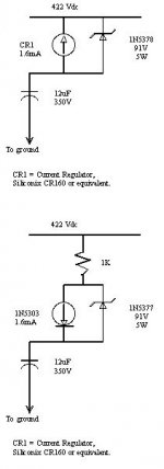
If the resistor is installed, it is there to protect CR3 (which protects CR1). CR1 is a current regulator diode with a mav aoltage of around 100V, D3 is a 91V zener diode to prevent an overvoltage condition. The intended voltage across CR1 is 45 VDC. This is consistance in all his designs that use that current regulatr diode. In this case it appears as though the 1K resistor was installed in case D3 conducts. In normal operation there is around 1.6 mA flowing in that circuit. A 1.4 w resistor is plenty but may not have a high enough voltage rating (we want it to go open in a fault).
I don't see a problem, but have never seen a unit with this part. It's easy to understand the purpose though.
-Chris
Hi Chris,
Yes, PRR went thru the circuit and described what was going on (headwize link).
He suggested replacing the CRD and the zener with a 27K-33K resistor (45V/1.6mA). I know Mike Elliot talks about replacing the "last vestitge of solid state sound" in his power supply upgrade, and figured it must be this CRD that he is talking about (they are just FETs).
PRR also could not understand why C56 (feeding the first stage) did not incorporate the 499 ohm resistor as the other feeds do (RC filtering), and suggested that I might want to try that. I've often wondered why C56 is so much smaller than C55, 57 and 58, but I guess he had his reasons (maybe too much capacitance with all 4 of them at 200uF?).
Well, I guess I will assume that I measured R140 correctly and put a 1K in (it was previously a Roderstein Resista which is 1/2 watt... I have some Dale RN60s or BC SMF25s, so will probably use the Dale).
From what I can see on every SA5.1 that I have seen internal pics of (the ones on AltaVista and a couple that I snagged from FS ads), that resistor is present. I was hoping someone had schematics that actually showed the 5.1 and not the 5. I'm not sure what you get if you order a service manual from Mike... i'd be a little ticked to pay $75 and get an SA5 manual
Thanks again Chris,
Chris
Yes, PRR went thru the circuit and described what was going on (headwize link).
He suggested replacing the CRD and the zener with a 27K-33K resistor (45V/1.6mA). I know Mike Elliot talks about replacing the "last vestitge of solid state sound" in his power supply upgrade, and figured it must be this CRD that he is talking about (they are just FETs).
PRR also could not understand why C56 (feeding the first stage) did not incorporate the 499 ohm resistor as the other feeds do (RC filtering), and suggested that I might want to try that. I've often wondered why C56 is so much smaller than C55, 57 and 58, but I guess he had his reasons (maybe too much capacitance with all 4 of them at 200uF?).
Well, I guess I will assume that I measured R140 correctly and put a 1K in (it was previously a Roderstein Resista which is 1/2 watt... I have some Dale RN60s or BC SMF25s, so will probably use the Dale).
I don't see a problem, but have never seen a unit with this part. It's easy to understand the purpose though.
From what I can see on every SA5.1 that I have seen internal pics of (the ones on AltaVista and a couple that I snagged from FS ads), that resistor is present. I was hoping someone had schematics that actually showed the 5.1 and not the 5. I'm not sure what you get if you order a service manual from Mike... i'd be a little ticked to pay $75 and get an SA5 manual
Thanks again Chris,
Chris
Hi Chris,
Don't pay the $75. You will get an SA-5 manual with possibly and update. At least it's not $90 any more.
The current reg. diode isolates the supply from the diode to some extend. Installing a resistor instead is simply not very intelligent. You could easily build your own CCS, but why? My own experiments indicate that using a CCS is hugely beneficial. Leave it in.
BTW, M.E always uses excessive capacitance. The quality of the 1K resistor will have little to no effect due to the high impedance of that circuit.
-Chris
I put the 1K in and went from there. It fired up fine (no flames) and the voltage at C55 measured fine (~240Vdc). However, I noticed a smell (like hot electric heat type of smell) and noted that V7 was running awfully hot. After things bled down after shutting it off, only the tube felt hot (resistors, etc. were fine). I fired it back up tonight, and still the same. Poking around a bit (still kinda a wuss with HV), I noticed that there was very little voltage drop across the zener (0.2V), and the voltage across C51 is ~420Vdc. I assumed that if the CRD failed it would go open and the C55 voltage would not come up... apparently not. It was only on a couple of minutes each time.anatech said:Hi Chris,
Don't pay the $75. You will get an SA-5 manual with possibly and update. At least it's not $90 any more.
The current reg. diode isolates the supply from the diode to some extend. Installing a resistor instead is simply not very intelligent. You could easily build your own CCS, but why? My own experiments indicate that using a CCS is hugely beneficial. Leave it in.
BTW, M.E always uses excessive capacitance. The quality of the 1K resistor will have little to no effect due to the high impedance of that circuit.
-Chris
BTW, the thing I did that led to all of this was replacing C51... the + lead wasn't trimmed enough, so was shorting to the case rail. I guess the CRD and zener are probably toast, so I will replace them (I have spares). Anything else you can think of to check from my bonehead move? The PSU unit seems fine (tho I will probably use Qdope on the board as you had suggested earlier in this thread).
Regarding the CCS, aren't there better ways of doing this than a CRD with a 100Vdc limit? From PRR's analysis (and he has no experience with Counterpoint stuff, but seems very experienced in tubes) it would seem that the zener is hit with a very large initial current at turn on while C51 charges, and if it fails, the CRD goes the next turn on cycle. It would seem that a resistor in parallel with an LED might be a better solution. At any rate, you have alot of experience with Counterpoint stuff, so I will defer to your recommendations. I at least figure that the CCS insulates somewhat from line voltage variation... mine seems to be high at 125-126Vac.
One other thing I wanted to ask you... you (and is it KBK?) appear to use RMAA to do the tube biasing? I am getting an m-audio firewire audiophile box and was going to setup a PC to run RMAA (I use a Mac, so no RMAA). I might want to ask you offline about how to go about doing this (I have a full "unofficial" as in free SA5 service manual with a couple of biasing procedures).
Thanks again,
Chris
Hi Chris,
Normally the zener will short when there is a problem, protecting the constant current diode. Remove the zener and measure for a short. I suspect a new zener will correct the situation. Now I understand why the 1 K burned out (and the zener). You can install a higher wattage zener. Do not increase the capacitance of C51. It's more than large enough. A 10 uF poly type cap would be an improvement due to it's improved HF response.
It is possible to improve the circuit with an LED biased current source, but the increase in performance probably will not help much. There is also filtering after the regulator. So there is no point unless the current regulator is gone and you can't get a substitute part.
To bias the tubes, I use a Leader LDM-171 distortion analyzer. I also monitor the residual on the other channel of my scope. RMAA would take far to long as you need to see the effect of your adjustments as they drift slowly in. You would be "stabbing" in the dark. Plus you need to make an input buffer to protect your card from damage. If you are interested in doing audio adjustment, consider picking up a harmonic distortion analyzer, good generator (Leader LAG 120A or better) and a dual trace 'scope. Once you have those, you can play with RMAA, but that will never completely replace proper instruments.
-Chris
I replaced both the zener and the crd. Seems to work. Still getting kinda high voltage on C51 to ground (~390Vdc). All the other voltages I checked were on the mark (84V on C52, 244Vdc on C55... I had already replaced R57 with ~42K to lower the voltage a bit.. may go back up to 47K or so). The zener has 24-26Vdc across it. C51 is a 22uf 350V Black Gate VK (already had it, so tossed it in). I might pick up something like a 10uf Wima MKP10 in 400V next time I order from TAW.anatech said:Hi Chris,
Normally the zener will short when there is a problem, protecting the constant current diode. Remove the zener and measure for a short. I suspect a new zener will correct the situation. Now I understand why the 1 K burned out (and the zener). You can install a higher wattage zener. Do not increase the capacitance of C51. It's more than large enough. A 10 uF poly type cap would be an improvement due to it's improved HF response.
I'll see what it sound like tomorrow night. Stupid question: do tubes such as V7 (6GC5) run pretty warm normally? It didn't seem as hot as last night with the bad zener, but still seems warm (haven't measured temp on it tho).
In post 127, smf used RMAA successfully to adust his pre... I need the m-audio box for something else anyhow, and have the PC for free. If the box has RCA ins and outs, what do I need an input buffer for? I'd just be inputting into a line in and possibly the phono inputs (I suppose I'd need to build the RIAA deemphasis circuit shown in the service manual for this), and reading from the main outs... all capacitively coupled? I'll give it a shot... if I need to I'll pick up a distortion analyzer or find someone to do it. Would the HP 334A be an approximate equivalent of the Leader? IIRC, the HP units don't require a separate signal generator. I have a Tek scope already.anatech said:To bias the tubes, I use a Leader LDM-171 distortion analyzer. I also monitor the residual on the other channel of my scope. RMAA would take far to long as you need to see the effect of your adjustments as they drift slowly in. You would be "stabbing" in the dark. Plus you need to make an input buffer to protect your card from damage. If you are interested in doing audio adjustment, consider picking up a harmonic distortion analyzer, good generator (Leader LAG 120A or better) and a dual trace 'scope. Once you have those, you can play with RMAA, but that will never completely replace proper instruments.
-Chris
Hi Chris,
-Chris
Voltage spikes and levels that can kill the input stage, or make it noisy. That's one of the differences between test gear and "other".In post 127, smf used RMAA successfully to adust his pre... I need the m-audio box for something else anyhow, and have the PC for free. If the box has RCA ins and outs, what do I need an input buffer for?
It's probably better if it's in good repair. Excellent choice. Your Tek is more than enough as well.Would the HP 334A be an approximate equivalent of the Leader?
Yup. Extra heater current as well as the voltage across the tube X the current to the circuits. If it arced it may damage the other tubes.Stupid question: do tubes such as V7 (6GC5) run pretty warm normally?
You really want around 45 VDC across it. That's it's "happy" range. You don't want to go too close to either extreme.The zener has 24-26Vdc across it.
-Chris
anatech said:Hi Chris,
Yup. Extra heater current as well as the voltage across the tube X the current to the circuits. If it arced it may damage the other tubes.
No signs of arcing. So your thought is things are OK?
anatech said:You really want around 45 VDC across it. That's it's "happy" range. You don't want to go too close to either extreme.
-Chris
Recall that R140 is in series, and should be dropping ~16Vdc, so 16 + 24 = ~40Vdc. I'm just curious... the CRD that is in there must not have as high of impedence/resistance as some if it is only dropping 24V across it? The circuits without the R140 still were supposed to drop 45V at 1.6mA? I have several CRDs (2 of the Siliconix CR160 as original; the one I put in was a 1N5303.)... should I try a different one and see if the voltage drop before C51 increases?
Thanks,
Chris (Pars)
Hi Chris,
You should have 45 VDC across your current regulator diode. The 1N5303 is the proper part. Ignore whatever is dropped across the resistor, it should be about 1.6 VDC for a 1 K value. The other resistor is a "fudge factor". It's only used to burn up extra voltage.
-Chris
You should have 45 VDC across your current regulator diode. The 1N5303 is the proper part. Ignore whatever is dropped across the resistor, it should be about 1.6 VDC for a 1 K value. The other resistor is a "fudge factor". It's only used to burn up extra voltage.
-Chris
Hi Chris,
oops, math error on the 1K drop.
I pulled the CRD and tested both it and the old one on a breadboard with a 1K resistor and a 9V battery. 1.65 and 1.67 mA respectively, so they both appear to be good. I took a look at R51 which is actually two resistors soldered in series. The measured 107K, not quite the nominal 75K as indicated in the schematic. However, they are Rodersteins, and are nicely soldered together, so I'm not sure it didn't come from the factory that way?
From looking at the circuit, it would appear that reducing this value would also reduce what I am seeing on C51, as it should work more or less like a voltage divider. I'm not sure if this would increase the voltage dropped across the zener/CRD. Have you seen the value of R51 played around with like this Chris? I assume it is to regulate the current going into V6 and V7. but I'm a newbie when it comes to tube circuits...
I'm certain that the zener and the CRD were in correctly (cathode stripe on zener towards mark and towards B+... crd in the opposite of this, as a normal diode would be.
Chris (Pars)
Attachments
Hi Chris,
The quality (type and construction) of that resistor means very little in that circuit position. It's a very high impedance circuit with a good quality cap to ground (bye, bye noise). Use a normal carbon film or, my favorite, metal oxide.
The amount of voltage dropped across that resistor will vary directly as the resistance changes. It has nothing to do with any tubes. It only determines how much voltage is dropped across the current diode. Start at 75 K and figure out what you need to get around 45 VDC across the diode. Most I see are 75 K in value.
-Chris
- Home
- Amplifiers
- Tubes / Valves
- Counterpoint SA 5.1