Yes, you should do the hum breaking resistor. Others have done it with success.
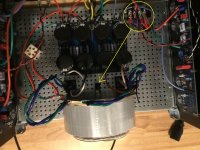
But before you give up on the arrangement in your picture of post #1040, I suggest you move the incoming AC and thermistors to between the PS board and transformer and at the centreline of the chassis. Also run the AC line from the IEC connector down the centreline of the chassis. The goal is to keep the AC away from the signal wires and the amplifier boards.
Also twist the V+ V- G wires together from the PS board until they reach the amplifier boards. Tightly twist the wires from transformer to rectifiers and rectifiers to PS board, input + and G, speaker + and G. They should be twisted tightly, not loosely.
Route the speaker and input signal wires close to the amplifier board on their way to the back panel.
Route the transformer secondary wires away from the amplifier boards on their way to the rectifiers.
Basically keep AC wires away from the signal wires and components and keep signal wires away from AC.
Once all this is done, rotate the power transformer to find the position of lowest or no noise.
Also be sure to have good ground connections between the two halves of the power supply board at the power output. I see empty ground pads. Connect the two sides with wires.
I forgot to mention, also tightly twist the AC wires from the IEC connector to the thermistors.
Attachments
Last edited:
Thank you Ben. I’ll see if I can fit that block between the PS board and the transformer. That might push the board too far under the IEC connector. I’ll also solder those last couple ground pads. And twist, twist, twist!
I wasn‘t comfortable with the space I had to move the block right behind the transformer with the PS board just off the base plate. Then I decided to use those 80mm stand offs to raise the PS board up so I could fit the block under it. That also raises all the wires from each amp board up so I can route and twist them better. Now there is no hum or any kind of noise at all from the speakers, just a little buzz from the transformer and Ican live with that.
I really appreciate the help and encouragement Ben and all.


I really appreciate the help and encouragement Ben and all.

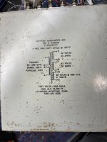
Has anyone used this transformer or have opinions on the companies quality in general?
https://toroid.com/wp-content/uploads/732.182-1.pdf
https://toroid.com/wp-content/uploads/732.182-1.pdf
I cannot find the Elna Silmic II 10uf 35v capacitor, nor can I find another audio grade cap at 10uf 35v. Thoughts/suggestions?
I just placed a Mouser order and found the same issue. Here s what I'm going to try:
https://www.mouser.com/datasheet/2/293/e_ufg-3082295.pdf
They are going to be obsolete so I ordered extras.
https://www.mouser.com/datasheet/2/293/e_ufg-3082295.pdf
They are going to be obsolete so I ordered extras.
Thoughts/suggestions?
use Silmic only to signal positions - input side and Aleph CCS modulation cap; for these, even 10V is enough
Well in that case I just ordered these. Hope they are authentic. Guy has good feedback. Fingers crossed. https://www.ebay.com/itm/1654415662...mO6m1wXTKC&var=&widget_ver=artemis&media=COPY
I need to look at my stuff. I think I have a couple from a previous project. Or see if this guy has them and just order them. Really sad they’ve discontinued them. Just like the Blackgates.
Ha! Mouser did actually have that value and I ordered them plus a couple extras. Should be good to go I think.
Appreciate the heads up regardless 👍
Appreciate the heads up regardless 👍
Just like the Blackgates.
Well, I stopped looking for these eons ago
Even then I was too old to wait for them to finally get fully Burn In
And even then they are not better than Silmics
Nothing really can beat Silmic bypassed with MKC ...... taking all in account
Good to know. I usually bypass the ps electrolytics in my tube amps with a film cap.
This is my first foray into a ss amp and figured this would drive my modded Heresies nicely.
I've yet to start on the case. It's still in the box. Building an mosfet amateur radio amplifier atm.
Theoretically it should produce 2800 watts of HF RF. If I can get 1200 I will be happy.
Sorry if I've polluted this great thread. Again, thank you Zen Mod for the info and what you give
back to the community. I lurk here a lot 😉
If I can get 1200 I will be happy.
just put it (mosfet(s)) in bucket of oil

Actually making a “lab” ps with it. I may post a photo of it on the power supply forum when it’s finished. Transformer is about 90 lbs. 40+ Kg for our friends across the pond.
- Home
- Amplifiers
- Pass Labs
- Aleph J build guide for noobs