Heatsink are an unnecessary expense. You can turn on without them! 🙂That's great that you can run classA amp without heatsink. That's the biggest expense in classA amps. Congrats to that.
I build few versions of AlephJ and they all required big modushop 4U chassis and worked very well with any speakers i tried.
Great amp.
I suppose the fact that you do not like the sound of AlephJ is some twisted italian humor too. Or messed up build?
Take a better look at the picture, I turned it with no heatsink, no power supply, and no input signal!That's great that you can run classA amp without heatsink. That's the biggest expense in classA amps. Congrats to that.
I build few versions of AlephJ and they all required big modushop 4U chassis and worked very well with any speakers i tried.
Great amp.
Quick update on my Aleph J. I have been listening to it for a couple of weeks now with a Schiit Freya S preamp and driving a pair of Zu Soul VI. I found the amp to sound extremely warm coming from the Elekit TU-8600S also on the Soul VI. I ended up removing C1 as suggested by @Extreme_Boky and noticed a definite improvement in clarity and bass definition. There is a definite weight to the sound now which I love. The TU-8600S doesn't do great with a lot of rock music IMHO, but the Aleph J sounds tremendous. I am loving the sound of the Aleph J more and more each day.
Now I am of course considering other builds such as the M2X lol.
Now I am of course considering other builds such as the M2X lol.

I found my noise issue, it‘s the ground wires from the amp boards to the PS (the green wires). As I move them around the noise goes louder or completely quiet.
Is there a recommended placement or routing for these grounds?
Is there a recommended placement or routing for these grounds?
Thank you for that link. I was seeing how moving the PS above the transformer would work, so things might have gotten bumped around. So far, the left side has no issues being twisted with the rail wires. The right side is a little louder twisted and is quiet pulled straight out to the PS and routed around a couple Caps.
This is just me testing and learning so not a big deal. I’m going to try the transformer on an L bracket next. It’s interesting how all this works!

This is just me testing and learning so not a big deal. I’m going to try the transformer on an L bracket next. It’s interesting how all this works!
Looking at your picture, perhaps the big issue is that the power transformer and the AC input of the PS board are very close to the input signal wires. If your transformer is an Antek, my experience with Anteks is that they leak a electromagnetic field from where their wires exit. So it is best to keep the transformer far away from the low level input signal. Adding to that is the location of the bridge rectifiers located near the front of the amplifier, which spread the AC field from back to front of the amplifier. So you have widespread electromagnetic in the middle of your chassis.
A bracket to mount the transformer at the front of the chassis is a good idea. Run the twisted AC wires from the IEC connector under the bottom plate straight down the middle of the chassis to the transformer. Also rotate the transformer to find the best orientation for lowest noise. My experience is to locate the wire exit points on the transformer so that they do not point toward the amplifier board.
Then locate the bridge rectifiers between the transformer and PS board. Orient the PS board with AC in toward the front and DC out toward the back.
Twist all wires - all AC to transformer and out of transformer, DC out of rectifiers to PS board, DC out of PS board (V+ V- G) to amplifier boards, signal and ground from RCA to amplifier board, and speaker out and ground from amplifier board to speaker connectors.
Another thing to do is the hum breaking resistor mod: Aleph J HBR
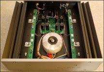
As another "Lessons Learned" datapoint, look at how the grounds are connected here, very slick and well thought out. So you have essentially a star ground on the amp board, where the PS ground, Speaker ground, and input grounds all share practically the same connection point. And notice how the connection point arrangements allow for twisted pairs all the way to the PCB... SPK +/-, DC rail +/-, input +/-... perhaps some prospective future PCB designers can maybe keep some of this knowledge in their "back pocket" to help minimize the potential noise problems by using some smart and clever practices like those you see from the fine FW / PL folks..
Attachments
Adding to another lesson learned. Be careful when trusting pictures, you may have turned your PS board around so that the + and - are now switched. If you do this you will absolutely blow a fuse. I may or may not have first hand knowledge of this.
By the way, will a GMA 3A 250V fuse be ok? That’s all I could find at the local hardware store. The one that was in there was T3AL 250V?
By the way, will a GMA 3A 250V fuse be ok? That’s all I could find at the local hardware store. The one that was in there was T3AL 250V?
Your GMA 3A fuse seems to be a fast acting one and may blow with the inrush current at start up. The "T" fuse is a slow blow one which helps to handle this.
Now I know how everyone feels chasing hum. Luckily I have an f6 working perfectly so I can work through this process with no time limits.
I went from almost nothing, you would have to be right next to the speaker to hear anything, to noticeable hum but back a couple feet no problem, to very noticeable hum you can hear between tracks. Now back to the transformer flat on the bottom of the chassis and the power supply on the face plate. I might give the hum breaker a try too.

I went from almost nothing, you would have to be right next to the speaker to hear anything, to noticeable hum but back a couple feet no problem, to very noticeable hum you can hear between tracks. Now back to the transformer flat on the bottom of the chassis and the power supply on the face plate. I might give the hum breaker a try too.
- Home
- Amplifiers
- Pass Labs
- Aleph J build guide for noobs