Decided to go in and do a quick and dirty movement of twisting some wires and moving ground and negative wires (not -24VDC) and basically moved ground from left channel board ground to left input - to left output - to right input - to right output - to what I hope makes a star ground and where 120VAC input ground is landed at star bolt.
I did leave a ground on the power supply so that it could "see" the star ground. No good, Still had 120hz hum. thought the heck with it and removed the ground off of the power supply board. Lo and behold a large drop in the volume of the hum. Done for today. Will probably resolder wires after twisting them better and for length. Thanks for input.
I did leave a ground on the power supply so that it could "see" the star ground. No good, Still had 120hz hum. thought the heck with it and removed the ground off of the power supply board. Lo and behold a large drop in the volume of the hum. Done for today. Will probably resolder wires after twisting them better and for length. Thanks for input.
Still there’s a slight hum when I hold my ear near the speaker. When the source isn’t plugged in I notice the buzz is louder when I touch the input lines. But when connected no amount of jiggling things around seems to make a difference. It’s a quiet hum- not perceptible when in use. But it’s def not dead quiet.
I ran the AC lines underneath the board. Rotating the transformer doesn’t seem to make a difference. As for options I followed those indicated in the newbie guide which I think is based in 6L6’s build guide.
Any thoughts for this newbie welcome.
Suggestions:
1.) Connect the IEC Ground to the chassis as close as possible as it exits the IEC connector. This is star ground.
2.) Connect shield (violet) of the transformer to star ground point on its own.
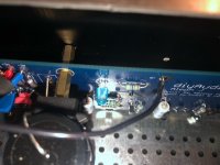
3.) Move GND wire (Green) to the L GND euro block terminal for the L amp board, do the same for the other channel. I believe you have L ground to R PSU connected and vice versa looking at the pic.
4.) Connect ground (GND) from PSU (from L or R euro block, preferably the closest one to the location of the star ground) to the thermistor, the other end of thermistor to star ground.
1) Agreed in terms of good practice, but I thought the star ground was related to audio ground, is it related to earth/chassis gnd also?
2) If so, why separate the shield gnd from the same point as earth/chassis GND and add the resistance of the perforated panel between? It would go against the principle of "star grounding", would it not? Mine are separate b/c I read that it simply didn't matter, and that a shorter shield wire was better. My transformers are at the front of the chassis, and IEC at the rear. I'm curious why you'd say to separate based on #1.
3) I don't think there is an "L" or "R" for the PSU. It's just the V+ and V- supply sides. They're not running dual mono. See previous posts from one person thinking L and R and the issues that ensued. One of the goals is to further reduce the resistance between the ground planes between the V+ and V- supply sides with additional jumpers suggested by Ben Mah for lonepine. If you're using L and R just to denote physical location, understood, but it can be confusing.
4) See above re: L and R. That may be confusing. Yes, shortening wires can have an impact, I believe, but it doesn't relate to one channel or another.
Chasing hum can be agonizing, and I love learning more from the threads, so if I have anything incorrect, please chime in.
Hi,
1.) A star ground is two or more grounds connected to one physical point where several ground wires connect forming a "shaped" just like a star. I do not think it is exclusive to power ground (0V), signal GND, or chassis GND (although all interact) connection/connections only.
2.) ???? What I meant is to connect the wire directly to the point where the IEC GND connection meets the chassis (star ground point). The violet wire is a static shield and not a power or signal ground.
3.).
Yes, I am referring to the picture posted. L and R is directional.If you're using L and R just to denote physical location, understood
Hello Folks
Just wondering what are the reasons for requiring a 10 amp fuse on the neutral AC? I never seen an amp with 2 fuses before, typically only on the HOT side
thanks
Just wondering what are the reasons for requiring a 10 amp fuse on the neutral AC? I never seen an amp with 2 fuses before, typically only on the HOT side
thanks
Because you want the fuse on hot to blow, not the neutral. The 10A is equivalent to having no fuse on the neutral.

The safest arrangement is to have one fuse only, and on the hot line only. Only if there is a fuse on the neutral line, then provide a high current fuse in that line to ensure that the hot line fuse blows first.
If there are two fuses and the neutral fuse blows, that leaves the hot line active and therefore the chassis/amplifier is still "hot".
If there are two fuses and the neutral fuse blows, that leaves the hot line active and therefore the chassis/amplifier is still "hot".
This question is also covered in the Build Guide blog: "The 10A fuse should go on the Neutral side, and the 3A on the Live side. This is meant to ensure that if there is a short to the chassis, the smaller Live fuse will blow first, and the chassis won't be a live shock risk."
I'm not sure how I missed it... better late than never.
Thanks very much Amandarae for the explanation and reply. Makes perfect sense. 🙂
Thanks very much Amandarae for the explanation and reply. Makes perfect sense. 🙂
The safest arrangement is to have one fuse only, and on the hot line only. Only if there is a fuse on the neutral line, then provide a high current fuse in that line to ensure that the hot line fuse blows first.
If there are two fuses and the neutral fuse blows, that leaves the hot line active and therefore the chassis/amplifier is still "hot".
So if I read this correctly, it's perfectly safe to run a single 3A fuse if your IEC socket has only room for one fuse? I did not buy the backpanel kit with double fuses holder from the diyaudio store..
Yes. If there is only one fuse in the IEC socket, it is safe. All of my amps have only one fuse in the IEC socket. Just make sure that your wall socket has the live and neutral wired correctly.
Hello Gents,
Completed the Aleph J amp last night, set bias to 400 mv and I have great sound!
However, noticed " LED2 " on both board does not light up, the other LED3 is fine. It's the light blue version that comes with the kit
Can someone help out, polarity is ok.
Completed the Aleph J amp last night, set bias to 400 mv and I have great sound!
However, noticed " LED2 " on both board does not light up, the other LED3 is fine. It's the light blue version that comes with the kit
Can someone help out, polarity is ok.
Not to second guess you, but are you sure the polarity is correct? One LED comes off the V+ rail, and the other comes off the V- rail. If you have sound and the amp is biased, then you have both supplies working. Maybe double-check. The board is nicely marked to show the position for the flat side.
Alternatively, you could have two burnt LEDs, but that's less likely. If they are burnt, check the value for the LED resistors to be sure they're not mis-stuffed.
Those are the simple checks I'd do first (in that order).
Alternatively, you could have two burnt LEDs, but that's less likely. If they are burnt, check the value for the LED resistors to be sure they're not mis-stuffed.
Those are the simple checks I'd do first (in that order).
I had similar problem, and discovered that instead of 47k resistors, i used 47M. Obviously, too dim, inspite correct polarity. Otherwise all biased well, sounding great.
Once I discovered my mistake, I did not bother desoldering megaohm resistors, the boards were already on the heatsink, I just piggibacked new resistor on top. All is good.
Once I discovered my mistake, I did not bother desoldering megaohm resistors, the boards were already on the heatsink, I just piggibacked new resistor on top. All is good.
I had similar problem, and discovered that instead of 47k resistors, i used 47M. Obviously, too dim, inspite correct polarity. Otherwise all biased well, sounding great.
Once I discovered my mistake, I did not bother desoldering megaohm resistors, the boards were already on the heatsink, I just piggibacked new resistor on top. All is good.
R28,R29 for both led's are 4.7k installed as per BOM list. I may have screwed up LED orientation - see photo. Is this correct?
So far this is the only boo boo on the build, so have been lucky!
Attachments
Last edited:
Resistors do not have orientation.
Only audiophile fuses and cables. That was a joke.
Sorry, i shifted decimal, i was writing from memory.
If it needs 4k7, thats what i put in.
When it is powered, measure voltage drop on the led diode. Should be like 1.7 to 2 volts.
Only audiophile fuses and cables. That was a joke.
Sorry, i shifted decimal, i was writing from memory.
If it needs 4k7, thats what i put in.
When it is powered, measure voltage drop on the led diode. Should be like 1.7 to 2 volts.
Resistors do not have orientation.
I know that part.. just was asking about the orientation of the led legs on the picture
- Home
- Amplifiers
- Pass Labs
- Aleph J build guide for noobs