As an early holiday gift to myself, I picked up an ancestor of the Aleph J. It's working alright, but it needs a little servicing at Pass Labs. Listening comparisons on the agenda for the weeks ahead. 🙂
I must say, spot on purchase! Anyone here would have done the same.....But, there is something sinister about this.
You came into this all "go easy, I'm a noob" and now look. You totally accomplished your build, wrestling all demons to submission!😀
However, this latest purchase shows an infestation of Pass-clone-DIY obsessive build disorder.
Not to be taken lightly, it will cost much money. And be dam well worth every cent. Yes even if the whole board goes up in smoke, not really a big deal.
Just don't burn the house down. Buy stock in Italian chassis sellers.
You are here.
Russellc

Oh yes. This purchase clearly shows how far the sickness has progressed.
This clear and present evidence that it has progressed far enough that the "I just want to build an amp and that's it" mindset has been destroyed, starting with "Well this would be nice too" and ending in a tailspin of having the dining room table covered with projects and sneaking items into the house. (I actually successfully snuck in and hid two 5cu ft JBL speakers past my 2nd wife...you were warned. But it's all good
Russellc
I'm having a bit of trouble uploading the images of the problematic board. I posted it on IMGUR and tried to link the images here, hope that's okay and not against the rules.
I wired in the other board and it's completely perfect, offset as close to zero as my meter will read and bias is steady and easily adjusted.
The problematic board, board number 1, gets a huge influx of voltage on powering on and off. I can adjust both offset and bias after power up but it doesn't seem like the change affects anything when I turn it on and off again. There's still a big spike of voltage. Hopefully these photos upload so someone can give me some direction.
I find tinning stranded wire makes it a heck of a lot easier to get a good solder joint
I'll definitely tin the solder wires next time before soldering, it was just a bit of laziness on my part.
I have to say I really am blown away by how good this amp sounds. I'm using an audio research sp9mkii as a pre and the amp sounds so powerful, it's incredible.
I did a final setting of the bias letting the amp warm up for about half an hour. I may have missed this in the guide but should I try to do another bias reading/setting with the top on the amp?
I also made one dumb mistake and did the entire bottom
plate on the inside of the amp upside down. I ended up just making it work though with longer screws. Still very happy with how this project turned out considering it's the first amp I've ever built. The noob guide is excellent, made all the difference and I'd love it if someone did another beginner guide for some of the other nelson pass amps.
Thanks so much for the help everyone, it's been a very fun project to work on around this holiday season and for my next two days off I don't think I'm going to do anything but listen to music haha.
I'll definitely tin the solder wires next time before soldering, it was just a bit of laziness on my part.
I have to say I really am blown away by how good this amp sounds. I'm using an audio research sp9mkii as a pre and the amp sounds so powerful, it's incredible.
I did a final setting of the bias letting the amp warm up for about half an hour. I may have missed this in the guide but should I try to do another bias reading/setting with the top on the amp?
I also made one dumb mistake and did the entire bottom
plate on the inside of the amp upside down. I ended up just making it work though with longer screws. Still very happy with how this project turned out considering it's the first amp I've ever built. The noob guide is excellent, made all the difference and I'd love it if someone did another beginner guide for some of the other nelson pass amps.
Thanks so much for the help everyone, it's been a very fun project to work on around this holiday season and for my next two days off I don't think I'm going to do anything but listen to music haha.
Biggest hurdle for me was the PS and it's connections. I never said I was the sharpest knife in the drawer.
Yes I used that video channel a lot as well as this guide. I'll have to look into their videos for other diy projects. I originally started with trying to build an f6 but I ran into a lot of problems building the board and decided to just start over using the aleph j boards as this guide is so good for beginners like myself.
I think I biased the boards properly. This time I left it on for a good hour with the top panel loosely on top and adjust the levels over time. It's not perfect though, one channel doesn't seem to want to hold bias at anything higher than about .390. still the amp sounds great so it's okay if it's a little under bias.
i want to get started on building something new as soon as possible. It's a very addictive hobby haha
Convinced to build the Aleph J


The best present under the tree this year was finding my way to this thread, your Build Guide Blog and 6L6's Aleph J Build guide. If I wasn't already convinced to make my plans to build this amp by @flohmann and his welcoming response to my post... I really appreciate the fantastic encouragement from @mkane77g and several others here:
@6L6 - Wow, now I have to build THIS amp! Well, really, I WANT to build it.
@ItsAllInMyHead - great eyes
@Will2226 - great finish and inspiring
I feel honored to join this group. I am starting feel the sickness, though. Like, what stuff can sell to buy all of the the parts? ASAP!
Now to watch the video links posted by @ Soundhappy
Thanks everyone! Happy New Year.
antennadad
The best present under the tree this year was finding my way to this thread, your Build Guide Blog and 6L6's Aleph J Build guide. If I wasn't already convinced to make my plans to build this amp by @flohmann and his welcoming response to my post... I really appreciate the fantastic encouragement from @mkane77g and several others here:
@6L6 - Wow, now I have to build THIS amp! Well, really, I WANT to build it.
@ItsAllInMyHead - great eyes
@Will2226 - great finish and inspiring
I feel honored to join this group. I am starting feel the sickness, though.
Like, what stuff can sell to buy all of the the parts? ASAP! Now to watch the video links posted by @ Soundhappy
Thanks everyone! Happy New Year.
antennadad
Definitely do it! Using this guide makes it so anyone with some basic knowledge at skill at soldering can do it. Best of luck on your build and happy holidays!
I'll definitely tin the solder wires next time before soldering, it was just a bit of laziness on my part.
I've found that on the rare occasion that I need to insert stranded wires like input wires "from the top" once the boards are mounted that tinning and trimming prior to soldering makes things much easier, and it gives me peace of mind that I won't have a little "hair" making contact with the heatsinks and shorting.
I have to say I really am blown away by how good this amp sounds. I'm using an audio research sp9mkii as a pre and the amp sounds so powerful, it's incredible.
I like Mkane77G's description. Makes music sound "easy"

I did a final setting of the bias letting the amp warm up for about half an hour. I may have missed this in the guide but should I try to do another bias reading/setting with the top on the amp?
Yes.
I also made one dumb mistake and did the entire bottom plate on the inside of the amp upside down. I ended up just making it work though with longer screws. Still very happy with how this project turned out considering it's the first amp I've ever built. The noob guide is excellent, made all the difference and I'd love it if someone did another beginner guide for some of the other nelson pass amps.
Later on, you can just tell everyone that you planned ahead to allow a bit more room between the bottom panel and your perforated plate to run your mains wiring. It's not a "mistake" per se. Many people do that intentionally, including me. 😀
Thanks so much for the help everyone, it's been a very fun project to work on around this holiday season and for my next two days off I don't think I'm going to do anything but listen to music haha.
😀


I feel honored to join this group. I am starting feel the sickness, though.
Thanks everyone! Happy New Year.
antennadad
We have a support group.

Happy New Year!
The noob guide/blog has been so helpful. With work picking up (and kids at grandparents post-quarantine) I cranked out the boards, and now I'm at slight impasse. I'm installing the MOSFETs- first on the Keratherm onto the heatsinks, then will tighten them down and attach them to the amp boards and solder.
There are a couple continuity tests:
1. Between the heat sink and the mounting screw (and fender washer) of the MOSFET: we want this to be conducting.
2. Between the heat sink and each of the 3 leads of the MOSFET- we want this not to be conducting.
Do we want to do #1 to ensure that we're placing the probe on a conducting part of the heatsink? If so it might be worth clarifying that in the guide. The reason is that at first I noticed that only about 1/2 of my MOSFETs' mounting screw/washer seem to be conducting with the heat sink. I then realized that the black anondized (?) surface of the heat sink is non-conducting, which leads me to assume that #1 above is to make sure that you've found a conducting part of the heat sink (such as a screw, or the mounting rails), prior to testing the MOSFET leads. Is that right?
Thanks,
Thanks!
Last edited:
You should use a fine sandpaper and clean any imperfections where the MOSFET's will be mounted. This will also expose some aluminium around the threaded holes, and ensure good conductivity between the screw head and the heatsink (for easy of testing for shorts🙂)
Smoothing-out the heatsink just before you mount the MOSFET's will help two-fold:
1. the heat transfer will be improved
2. you'll ensure that any metal shredding, that could still be there as a leftover from machining/cutting the threads, will be smoothed-out to prevent damage to Keratherm insulators and the consequent short between the heatsink and MOSFET's once the things get (really) tight. This could potentially become a tricky issue down the track, because the short may not manifest immediately, but later... down the track... due to thermal / Keratherm setting-in and possible re-tightening of MOSFET's after a month or 2 🙂
Last edited:
Yes. You are correct. You don't want a false negative test.
Edited to add - that'll teach me to refresh. Also see Extreme_Boky's excellent recommendations above. 🙂
Edited to add - that'll teach me to refresh. Also see Extreme_Boky's excellent recommendations above. 🙂
I don't remember sanding the heatsinks but then again it was 4 years ago that I started this build. That will be next on the agenda, a separation of the to to check.
Good idea or bad?
Good idea or bad?
The noob guide/blog has been so helpful. With work picking up (and kids at grandparents post-quarantine) I cranked out the boards, and now I'm at slight impasse. I'm installing the MOSFETs- first on the Keratherm onto the heatsinks, then will tighten them down and attach them to the amp boards and solder.
There are a couple continuity tests:
1. Between the heat sink and the mounting screw (and fender washer) of the MOSFET: we want this to be conducting.
2. Between the heat sink and each of the 3 leads of the MOSFET- we want this not to be conducting.
Do we want to do #1 to ensure that we're placing the probe on a conducting part of the heatsink? If so it might be worth clarifying that in the guide. The reason is that at first I noticed that only about 1/2 of my MOSFETs' mounting screw/washer seem to be conducting with the heat sink. I then realized that the black anondized (?) surface of the heat sink is non-conducting, which leads me to assume that #1 above is to make sure that you've found a conducting part of the heat sink (such as a screw, or the mounting rails), prior to testing the MOSFET leads. Is that right?
I'm glad the guide has helped! I have clarified the continuity test discussion in the guide, and also added @Extreme_Boky's suggestion to lightly sand the mounting area on the heatsinks before mounting the MOSFETs.
I see that I did my continuity test by touching my probe to one of the other pre-drilled holes on the heat sink, so I've clarified that in the text.
Last edited:
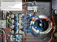
120hz sound coming from speakers.
Back at it after sitting out for a while. This has never worked, not complaining just a FYI for help with the problem. 120hz sound out of speakers just being powered up.
See pictures for more information as to what has been done. Bypassed soft start board (removed) and bypassed speaker protection board.
Grounds landed and taken off. Still same 120hz sound out of speakers.
Bias was set at 4.0mv but lowered it to 3.50mv to a more lower chassis temperature.
The scope picture was taken with light off to get the signal trace to show up on camera.
Scope readings were basically the same most everywhere on the chassis with trace mostly staying the same in amplitude.
Tried jumping with alligator clip wire from ground to neutral TB neutral (4) to see if hum sound changed and it did not.
Voltage measurement;
left right
R7 4.68v 4.65v
R16 430mV 456mV
R17 420mV 441mV
R18 423mV 426mV
R19 440mV 427mV
Q2 14.0v 13.37v
Q3 4.60v 4.60v
Q4 4.60v 4.70v
Bias 3.50mv 3.50mv
Did not check Q1A or Q1B. (worried about getting into tight spot.)
Have build two Amp Camp 1.6 versions and they work fine.
I see others and use what help you give them also. Appreciate what ever help you can give for ideas to try. Tried to anticipate questions to me, so hope most are covered as to what has and has not been done. Don't need you guys to do all the legwork. Thanks and happy new year.
Attachments


- Home
- Amplifiers
- Pass Labs
- Aleph J build guide for noobs