4x4F150 - well done! Your soldering looks great. That new switch does look like it's going to be a good fit. I love your high rez photos!
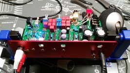
Hey I see one thing I would suggest doing. The bolts holding the 4 voltage regulators onto the rear panel could be tightened some more. In your photo I can see the lock washers are still mostly expanded. When the bolts are tightened down all the way those washers will be pretty much mashed flat. That will give you the best thermal transfer to the panel. After you do that though it would be a good idea to repeat that step of doing an ohm meter reading from the tab of each regulator to the panel to make sure it is a much higher reading than dead short (10,000 to over a million ohms, etc). The inside machined surface of any of the top vent holes is a good place to measure to since the insulating anodization has been removed. The measurement just makes sure the mica insulators are still doing their thing.
FPE does do great work, I have to hand them that. Hey speaking of FPE, I just posted a tip in the O2 Booster Board thread that was brought to my attention by Algar_emi. Turns out the color fill is fairly pricey. He discovered that eliminating the color fiil (the "no fill" option in the FPD editor), so that just the aluminum showed through the text, cut off something like $7 on the ODA front panel and $5 on the rear if I'm remembering correctly. So you are right, that probably would have been a good way to go rather than the grey fill. I had tried several different variations of things in FPE's editor to lower the price, but I hadn't tried that. A big thanks to Algar_emi for sharing that one!
Interesting - looking at your photos I think that if I should do another spin of the board in the future I probably will move those 3.5mm jacks forward a bit to eliminate any chance of that problem fmcclell has run into. I designed that so as to not have a lot of the threaded nose sticking out past the washer. But given that tolerances on cases, boards, and parts are what they are, having the nose of the jack stick out a bit past the nut is probably the best way to go. Lets see how yours (3.5mm input jack vs. the nut and panel) works out. 🙂
Last edited:
Hey I see one thing I would suggest doing. The bolts holding the 4 voltage regulators onto the rear panel could be tightened some more.
Yeah I only have those "hand tight". I misplaced my tiny needle nose pliers and didn't feel like looking for them and it was getting late last night, so stopped for the day. I did a preliminary test and all 4 chips are fully insulated (DM measuring infinite resistance) but I will check again after I tighten them down.
I should probably explain more of what I did for anyone that may attempt this build and use my pics as reference:
Step 8 - instead of using jumpers for R88 and R89 (which the directions call for), I put in a DPDT switch that takes as input R88 and R89 and the output goes to one of two places - [other side of R88 and R89] or to [JP21 pin 1 and pin 3]. When the switch is in one position it will act just like a jumper across R88 and R89 and when the switch is in the other position, it will give the output to the front panel pre-amp rca jacks. Everything else was done as described in the instructions.
Step 9) Because of the switch explained above, I did not install any of the preamp parts other than R90 which provides ground to the preamp rca jacks.
Step 10) Normal.
The reason for the switch is that I want to control the volume on a pair of powered speakers with the preamp output or listen to headphones with only one volume knob on the ODA. I don't want to unplug the headphones or speakers depending on what I am doing on my computer. I will simply have to push a button and pay attention to the gain when switching between the two. 🙂
I know the general audience here probably doesn't need my explanation, but after the google bots crawl this site, I'm sure it will help somebody research an ODA.
4x4F150 - I caught you mid-build then on those vreg nuts. 🙂 Good deal. Thanks for the details on the switch! That will help others.
IT'S ALIVE!!!... (cue evil sounding music)... IT'S ALIVE!!!!!
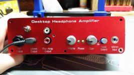
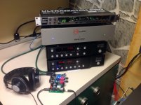
All the measurements tested well and plugged in my cheap throw-away phones (you can see them in the second pic and its even missing some plastic trim on the right side lol). And... there's sound. 😱
But seriously, the amp sounds good on the crap headphones. They are pretty sensitive and with no source playing, I can hear only a little hiss when the volume is all the way up on the 1x (lowest) gain. It goes away on any of the higher gain settings. I also double checked that music does get louder as you go clockwise on the gain knob so its not like I flip-flopped something. This seems kind of counter-intuitive to me as the hiss "should" get louder as the volume goes up.
About the build...my drilling of the extra hole turned out pretty well... not as good as the FPE laser cut holes, but definitely doesn't stick out as bad and I think if I didn't tell anyone, they would not notice. The 3.5mm input jack stuck out far enough for me to get about 1.5 rotations of the nut. I did have to kind of squeeze the front and back panels together to get the nut on; just laying there it didn't exactly stick out the hole. I think it would be a good idea to move it forward just a bit if not too complicated of a layout change.
I didn't put in the enclose screws yet because I have a few questions before I "button this up":
Is it normal to have a little hiss at the lowest gain and max volume? (If there was actually music playing, there would be no way to hear this)
My negative voltage did measure a little lower than my positive +12.48 and -12.40, I assume these are within spec but is it normal for the negative to be that much lower?
Finally, is it "safe" to use my good headphones or should I do a few hours of listening with the throw-away ones? (I've only listened to 2 songs so far, but the amp has been on for about an hour while testing)
I will post a subjective review of the ODA vs my computer headphone amp after I get enough guts to plug in my good headphones. lol
Attachments

IT'S ALIVE!!!... (cue evil sounding music)... IT'S ALIVE!!!!!
Well congratulations! 😀 That represents a lot of detailed work.
I will move those 3.5mm jacks forward a bit on any future board spins. I was about to post a suggestion for fmcclell on that. A good way to move the PC board forward a bit is put a thin screwdriver blade between the rear panel and the PC board and pry the board forward a tiny bit. With the regulators bolted down that will safely bend all the regulator leads just slightly and move the board forward so it can be flush with the front of the case. Don't turn the screwdriver sideways (rotational) to pry though, bring it in or out slightly so the whole flat part of the blade remains in contact with the PC board. That will prevent any "notch" damage to the board.
I'll bet I know what the hiss is. 🙂 It looks like you are using the rear RCA jacks for input. Change your input select switch to the front panel 3.5mm jack and leave that jack with nothing connected. Is the hiss still there? The 3.5mm jack automatically grounds itself when nothing is plugged in, just as with the O2. But not so for the rear RCA jacks. When nothing is plugged in, or if a cable is plugged into but there is no signal, there is nothing to ground the jack and you may hear hiss. This is true with any RCA jack device. To ground an RCA jack there are RCA shorting plugs that can be plugged into the jack, or at the end of an unconnected cable. Once the source device is powered up through the issue goes away since the RCA inputs are no longer floating.
You are right though, in general hiss should get louder as the gain goes up. If that test above doesn't solve it please let me know if the hiss is in just one channel or both, and if both is it about equal. Also let me know the impedance and sensitivity of your test phones (or manufacturer and model number).
Those voltage readings are OK. For amps it is more common to read something like +12.7 and -12.2. To have variation out on the second decimal place is really a close match. But... I designed it specifically so you can get that just as close as you want! 😀 That is what R33 and R36 are for, the small value 40.2R and 60.4R resistors in series with the main 1.65K set resistors. You can increase or decrease those as you wish to get the rail voltage just as close as you want. So for example with the 40.2R you could go to 39.7R or 41.2R - both in stock at mouser for 1206 SMD thin film. But electrically it really won't make a hill of beans difference. All that happens is at the very highest volume levels the output wave will hit one power supply rail 0.08V before it clips on the other. It would even be hard to see that much difference if you were feeding in a sine wave and watching the output on a scope.
Why you get a voltage rail difference at all is the +/- tolerance of the voltage source built into the regulator chips. Because of that there will always be some reference voltage variation between regulator chips, so a given set of "set" resistors like this will always yeild slightly different output voltages. If you were to try 5 different LT3015s for example you would get 5 slightly different rail voltages. The variation is small though, and if a closer match is needed the best solution is the above to just move the set resistor values up or down a tiny amount as needed. 🙂
On using your real headphones, how did your DC output offset voltage test come out? How much DC are you reading on each channel? That determines the safety. If the trimmers are adjusted properly the DC output should be very low, like 20 microvolts, or just plain old zero on a meter that only reads down to 1mV. I would recommend running it for, say, 30 mininutes or so with test headphones before plugging in the real thing. It can take about that long for any electrolytic capacitors that are soldered in backward to smoke and/or blow their cans off.
Last edited:
I'll bet I know what the hiss is. 🙂 It looks like you are using the rear RCA jacks for input. Change your input select switch to the front panel 3.5mm jack and leave that jack with nothing connected. Is the hiss still there?
Yes but I think you are correct on it being a grounding issue. Since I don't have the screws in the front or back plates yet, I don't think the front plate is grounding that well to the rest of the enclosure. If I pick up the amp off the table, the noise goes down (me grounding it more). And then if I squeeze the front and back panels against the enclosure, it pretty much goes away (grounding even more).
On using your real headphones, how did your DC output offset voltage test come out? How much DC are you reading on each channel?
My DMM is able to read down to 0.1 mV and they started at 0.5 mV and 0.2 mV for left and right respectively. I turned the trimmers until my DMM read 0 for both left and right. I tested using the 3 JP points right behind the 3.5 mm headphone jack. Pretty sure those are at the same potential as the jack and easier to measure using those holes. 🙂
Tomorrow I will make the "final" assembly and test some more.
4x4F150 - That does sound like lack of the (sheilding) case. Time to box it up and give it a listen! 😀 Those DC offset levels are OK.
I took the amp with me into work today and used it practically all day just to make sure everything is all good. I listen to the radio all day in my office so I ran my radio to the amp and then to my cheap headphones. I know not the best sound quality being radio, but it was a good endurance test... no smoke 😀
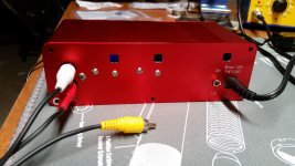
Got the case all "sealed" up... the hiss / background noise is totally gone. 🙂
But I did have one problem... those screws that come for the front and rear panels are cheap. The screw head in the upper right of the front snapped off before it even made contact with the panel. Now I have a stuck screw shaft in the enclosure. Not a big deal but cosmetically it hurts. My drill was even set to low speed and torque; and I wasn't even using full speed of the low setting.
I'm pretty impressed with the bass extension on this thing. Might be me just getting used to my new Hifiman HE-400 but it seems like there's more down low with the amp vs my computer's headphone amp. Even right now, I'm listening to some STP and enjoying every second of it. I see many hours of enjoyment in my future.
Edit - OK just found my first problem... when using the RCA input on the back, the left and right channels are flip-flopped. If I use the 3.5mm input on the front, everything is good... how in the hell was I able to do this? Have to start going back over my photos to see if I can find a mistake. (I triple checked the cord and even tried 2 different RCA cords, both with same result)
Last edited:
I took the amp with me into work today and used it practically all day just to make sure everything is all good. I listen to the radio all day in my office so I ran my radio to the amp and then to my cheap headphones. I know not the best sound quality being radio, but it was a good endurance test... no smoke 😀
No smoke is a very good thing! 🙂 Good idea though on the endurance test. It certainly can't hurt with new parts. I've seen probability distributions of MTBF over the years that essentially say if the part lasts the first hour/day, and is operated within electrical and mechanical parameters, it will last the next 5/10 years, etc. Essentially a part "infant mortality" issue with electronics. Here is an interesting read on it all:
The Bathtub Curve and Product Failure Behavior (Part 1 of 2)
The authors have coined the term "bathtub curve" for the sort of distribution that results.
Got the case all "sealed" up... the hiss / background noise is totally gone. 🙂
Interesting! That is some helpful feedback. Goes to show how much EMI is around all the time. It sounds like those countersunk single point grounds on the case are doing their thing to make an effective Faraday cage, at least around the audio band. If anyone is putting their ODA in a non-metal case a way to get some additional shielding is spray the inside with conductive paint and ground it to the input jack ground, or if a see-through case consider lining the inside with window screen or other metal mesh and ground that.
But I did have one problem... those screws that come for the front and rear panels are cheap. The screw head in the upper right of the front snapped off before it even made contact with the panel. Now I have a stuck screw shaft in the enclosure. Not a big deal but cosmetically it hurts. My drill was even set to low speed and torque; and I wasn't even using full speed of the low setting.
Is (hopefully) enough of the broken screw sticking out to get a pair of lockjaw pliers on it and twist it back out? I have a bunch of those screws here in both black and silver. I'll send you out a couple of new ones. If there isn't enough of the screw shaft left to get lockjaws on I'm not sure what more could be done to get it out. The aluminum case would be softer than the screw so drilling it out wouldn't work. I think an argument could be made for a defective case there to Allied or Newark - worth a try at any rate!
I have noticed the screws get tight on their way in. Makes me wonder if some galling is going on between the aluminum and whatever the screw is made out of. I think I'll try getting some anti-seize compound for aluminum like this
http://www.amazon.com/Vibra-TITE-Aluminum-Anti-Seize-Compound-Lubricant/dp/B008D6FGUC
and give it a try. If it helps I'll post.
One suggestion I have in general for those screws is, if possible, use an impact driver rather than a drill with a torque clutch. I use this one:
Makita 12-Volt Max Lithium-Ion Cordless Impact Driver Kit-DT01W - The Home Depot
Impact drivers are worth their weight in solid gold! 🙂 I would highly recommend these (any brand is great) to anyone for a thanksgiving gift to themselves. 🙂 That is when I picked this one up, one of the black friday sales. They don't munge stuck screw heads at all getting them out the way my drills used to do. I use the thing all the time for driving screws into wood and metal and breaking loose stuck bolts. In the other direction they are much less likely to twist screws off like that on the way in. I bought a hex shank torx bit and have have been using it with the box enclosures panels mainly to save my wrist from all the twisting, but I have noticed the drill having to work harder on that last 1/3 or so of the screw travel.
I'm pretty impressed with the bass extension on this thing. Might be me just getting used to my new Hifiman HE-400 but it seems like there's more down low with the amp vs my computer's headphone amp. Even right now, I'm listening to some STP and enjoying every second of it. I see many hours of enjoyment in my future.
Lol - I'm an STP fan too and can tell you that a bit of the ODA's design was done listening to some STP from way back when. 😀
Edit - OK just found my first problem... when using the RCA input on the back, the left and right channels are flip-flopped. If I use the 3.5mm input on the front, everything is good... how in the hell was I able to do this? Have to start going back over my photos to see if I can find a mistake. (I triple checked the cord and even tried 2 different RCA cords, both with same result)
Easy solution - swap those RCA jack inputs. 🙂 What colors does your RCA jack have on the top and bottom.? I believe the Kobiconn has different colors from the Switchcraft. I don't think there is anything you could do in the build to swap channels. Hmm... I just looked at the BOM and I don't see the Switchcraft listed as an alternate. I'll look into that. Mouser was out of stock of the Kobicon for quite a while and the switchcraft was an exact duplicate, at Digikey.
Last edited:
Is (hopefully) enough of the broken screw sticking out to get a pair of lockjaw pliers on it and twist it back out?
No nothing sticking out to grab with pliers. I have some interesting backing out tools around here for broken bolts in cars, but will have to check to see if I have anything small enough for this.
I think an argument could be made for a defective case there to Allied or Newark - worth a try at any rate!
Definitely, I bought it from allied so I'll contact them to see what they say.
Easy solution - swap those RCA jack inputs. 🙂 What colors does your RCA jack have on the top and bottom.?
Yep, swapping the inputs was the first thing I did. I bought the Kobiconn ones and they are red on bottom and white on top. I was looking at the schematic and I think I found the problem... If you look at one of my photos where you can see the rca jack on the backside, the side of the jack closest to the side of the enclosure goes to the top and the one toward the middle of the board goes to the bottom jack. This makes JP1 pin3 (closer to side of enclose) go to the top (white) and JP1 pin 1 go to the bottom (red). The schematic says the opposite about JP1. So I bet even though the Kobiconn and the Switchcraft have red and white in the same positions bottom and top, they wire them up different on the back of the jack.
You can see all this really well if you zoom in on post 760 second pic. The top view here shows the connectivity on the back of the rca going to the board and JP1 labels.
Red and white colors swapped on Mouser vs. Digikey RCA jacks
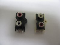
Well look what I just discovered, below. The black plastic one on the left is the CUI (I was wrong about it being Switchcraft) from Digikey while the white plastic one on the right is the Kobiconn from Mouser. Hmmm... now what is wrong with this picture.. 😛
Turns out these are both the ones I have in the BOM right now for the RCA jack in the Mouser and Digikey columns. They are identical from a physical size and mechanical mounting footprint standpoint. In the second photo it shows they are wired the same in terms of which PC hole the top RCA goes to. The colors are just switched. Thanks goes out to 4x4F150 for the discovery!
I just did a bunch of Google searches on the whole thing. It sounds like there really isn't a strong standard here. I've just looked at the TV and a few other devices around and they all have red for the right channel, but some of the reading says that white has been used for right too.
Luckily Digkey offers USPS shipping unlike Mouser, which is fairly cheap, if you want to swap jacks. I also have those CUIs I'll sell to anyone working on the ODA at cost ($1.67 plus postage) if you want to switch jack colors - just send me a PM. 🙂 The good news is the jacks should come out fairly easily with solder wick since the holes are large. You can snip those two plastic lock tabs that go through the PC board off with wire cutters. For that matter can probably snip the leads off too on the top of the board, then just unsolder the remains from the holes.
It looks like I'm going to be posting yet-another revision of the BOM in a few days. I will add a note in the notes column about the colors of the two jacks being switched, but I'm going to leave both on the BOM in case some prefer white on the top.
In other ODA news Mouser has started stocking a 1 ohm 1/8W metal film 1% resistor. I'm also going to start specifying that for the twelve output resistors going forward rather than supplying twelve 0.5R 1/8W 1% resistors with the board. Mouser and Digikey still don't have a 0.5R 1/8W resistors, but I've found from tests there is just zero difference in any of the measurements (except for a tiny almost unmeasureable increase in output impedance) in going from the 0.5R to the 1R balancing resistors. With this change folks can buy the resistors from Mouser and there will be no ongoing need to include them with the boards. This will be on the BOM revision.
Note that these are not the same as the 1R output balancing resistors that NwAvGuy used in the O2 headamp. Those were 1/4W and longer at 7.1mm vs. these 3.9mm. There is no need for 1/4W - only about 8mW maximum is dissipated - he just used those since Mouser didn't have the 1R 1/8W at the time. Lol - and that unfortunately cost him a lot of board space too since there are 4 of them.
I bought the Kobiconn ones and they are red on bottom and white on top.
Well look what I just discovered, below. The black plastic one on the left is the CUI (I was wrong about it being Switchcraft) from Digikey while the white plastic one on the right is the Kobiconn from Mouser. Hmmm... now what is wrong with this picture.. 😛
Turns out these are both the ones I have in the BOM right now for the RCA jack in the Mouser and Digikey columns. They are identical from a physical size and mechanical mounting footprint standpoint. In the second photo it shows they are wired the same in terms of which PC hole the top RCA goes to. The colors are just switched. Thanks goes out to 4x4F150 for the discovery!
I just did a bunch of Google searches on the whole thing. It sounds like there really isn't a strong standard here. I've just looked at the TV and a few other devices around and they all have red for the right channel, but some of the reading says that white has been used for right too.
Luckily Digkey offers USPS shipping unlike Mouser, which is fairly cheap, if you want to swap jacks. I also have those CUIs I'll sell to anyone working on the ODA at cost ($1.67 plus postage) if you want to switch jack colors - just send me a PM. 🙂 The good news is the jacks should come out fairly easily with solder wick since the holes are large. You can snip those two plastic lock tabs that go through the PC board off with wire cutters. For that matter can probably snip the leads off too on the top of the board, then just unsolder the remains from the holes.
It looks like I'm going to be posting yet-another revision of the BOM in a few days. I will add a note in the notes column about the colors of the two jacks being switched, but I'm going to leave both on the BOM in case some prefer white on the top.
In other ODA news Mouser has started stocking a 1 ohm 1/8W metal film 1% resistor. I'm also going to start specifying that for the twelve output resistors going forward rather than supplying twelve 0.5R 1/8W 1% resistors with the board. Mouser and Digikey still don't have a 0.5R 1/8W resistors, but I've found from tests there is just zero difference in any of the measurements (except for a tiny almost unmeasureable increase in output impedance) in going from the 0.5R to the 1R balancing resistors. With this change folks can buy the resistors from Mouser and there will be no ongoing need to include them with the boards. This will be on the BOM revision.
Note that these are not the same as the 1R output balancing resistors that NwAvGuy used in the O2 headamp. Those were 1/4W and longer at 7.1mm vs. these 3.9mm. There is no need for 1/4W - only about 8mW maximum is dissipated - he just used those since Mouser didn't have the 1R 1/8W at the time. Lol - and that unfortunately cost him a lot of board space too since there are 4 of them.
Attachments

Last edited:
Digikey RCA jack is red for right channel, Mouser is white
I traced out the wiring today. Using the standard TRS jack "ring for right channel" the Digikey CUI-brand RCA jack gives red for the right channel and white for left. The Mouser Kobiconn-brand RCA jack gives white for the right channel and red for left.
The LT regulators already have to come from Digikey. I've been keeping those on hand here too so folks don't have to place a separate Digikey order. I'll do the same with these jacks going forward. If anyone who has built an ODA wants the Digikey jacks the shippiing is on me, just send me a PM. 🙂 I should have noticed this difference in jacks long ago and had a note in the BOM. I'll sell them at cost, the $1.67 each that Digikey charges.
I traced out the wiring today. Using the standard TRS jack "ring for right channel" the Digikey CUI-brand RCA jack gives red for the right channel and white for left. The Mouser Kobiconn-brand RCA jack gives white for the right channel and red for left.
Mystery solved 🙂 My "educated" guess on the problem was based on 2 assumptions, red was supposed to be on the bottom and red is supposed to be the right channel.
There really is no real "rule" here... I too have searched the internet and red being the right channel is nothing more than a suggestion that is followed by most.
I all honesty, it's really not a problem and the amp is operating flawlessly.
ODA up and running - Very good indeed
This is my main headphone and test dac rig with a Mark Levinson ML 37 transport, ML360S dac, Beringher rate converter and other dac AD1865 dac with tube output. I have currently two main headphone amps, PS Audio GCHA, balanced version, and my best, my own DIY version of the all discrete, all fet Borbely Class-A headphone amp. Single ended interconnect Furutech OCC and Furutech RCA connector. I know overkill 😎 but if the ODA sounds good with this kit, it is that good.
Well first impression is excellent, probably at least as good as the much more expensive PS Audio!
Right out of the bench the ODA is just great. I'm sure it can get just better with some burning.
Thanks again AGDR for such a great design and all your hard work with the 4-layers pcb design. I think it is a success 😀
Bye
Attachments
Algar_emi - hey thanks for the listening feedback and the photos of your gear! That is always great to hear that the ODA is holding its own vs. a much more expensive amp.
You definitely had one of the speediest builds too, including tracking down that bad transistor! 🙂
You definitely had one of the speediest builds too, including tracking down that bad transistor! 🙂
Try Milk of Magnesia as a case screw anti-seize compound
Lol, the title is actually not a joke. 🙂 I've done a bit of research into the problem 4x4F150 ran into of the case screws on the Box Enclosures cases galling/seizing with the aluminum on the way in and snapping off. Turns out a cheap and effective solution is to coat the threads with unflavored Milk of Magnesia of all things. The water evaporates leaving a coating of magnesium oxide which makes a nifty dry lubricant. I've just tried it on a set of B4-080 case screw and seems to work great.
The anti-seize compounds in the auto parts stores are more iffy given that they contain copper and graphite, which from the reading can promote corrosion.
Lol, the title is actually not a joke. 🙂 I've done a bit of research into the problem 4x4F150 ran into of the case screws on the Box Enclosures cases galling/seizing with the aluminum on the way in and snapping off. Turns out a cheap and effective solution is to coat the threads with unflavored Milk of Magnesia of all things. The water evaporates leaving a coating of magnesium oxide which makes a nifty dry lubricant. I've just tried it on a set of B4-080 case screw and seems to work great.
Just have to laugh about this... but I'm going to do it.
And speaking of the case/screws problem I had... have to give a little bit of shout-out love to Allied Electronics. I took adgr's advice and e-mailed them about my problem with the screws heads breaking before meeting and clamping the front/back plate onto the enclosure... Allied sent me a new case no questions asked! Didn't even have to pay for shipping or return the case with broken screws in it... now that's what I call customer service! 😀 This was my first ever purchase with the company and all I bought was the enclosure from them, so this really did shock me. Can't recommend Allied Electronic enough for purchase of the enclosure for this build.
Going to drug store for some special milk before I put the screws into the new enclosure. 🙂
Last edited:
4x4F150 - I'm glad Allied came through! I've had to do that several times with Mouser but never have dealt with Allied customer service. Allied has a few of the other O2 parts too, including the power transformer.
Good luck with the MoM! 🙂
Good luck with the MoM! 🙂
All Done!
Well it took me about 1.5 months but I can say my ODA is officially done. Everything is functioning as expected and sounding great.
Don't know if it was the milk of magnesia or just better batch of screws/enclosure but the case is all closed up with nothing broken 🙂 It still seamed like there was the same amount of resistance, but there wasn't really that much when I broke the other screws either. I really took my time with the drill this time and went nice and slow. (The cashier at the store gave me a really weird look when I checked out with MoM and a 12 pack of my favorite beer... I'm sure not a normal combination 😀)
Also have the replacement RCA jacks in with the red on top / white on bottom layout. I may be pretty decent at soldering but I truly suck a de-soldering. Maybe my de-soldering wick is just sub-standard but I cannot get it to suck up the solder as easily as I see in youtube videos. I had to use the wick to get some of the solder and then push out the rca leads with the soldering tip and finally use the wick again to get some more solder from the hole. Only then was I able to pull the bad jacks from the board.
High praises to agdr for all the help and letting me steal some extra parts. I could not have imagined a more successful first DIY audio project. My only problem is now I have something else I like to spend my money on.
4x4F150 - congratulations on your build!! 🙂 It represents a lot of careful soldering.
Getting anything with more than 2 legs out with solder wick is tough. You did the right thing by pushing the leads out with the iron, best to get it to the point of just getting the individual leads one by one with the wick. Cutting up the jack is also OK, just to leave the 3 leads then unsolder them one by one.
LOL on the MoM purchase!! The checker probably made a mental note to avoid that brand of beer. 😀
Last edited:
- Home
- Amplifiers
- Headphone Systems
- A version of an O2 Desktop Amp (ODA)