I'll put a jumper 1206 resistor in the envelope on Monday too.
Thanks but I have extra 0 ohm jumpers (its was one of the few items that were cheaper on digikey... actually buying 10 is cheaper than buying 4 which is what the BOM calls for, so I have plenty)
I don't need to keep sucking up all your extra parts 🙂
Maybe I'll stick that button in the back of the case. That way if it doesn't look as clean as I would like, it won't matter as much... after shelling out 80 bucks for front panel express, I really don't want to touch those panels. I'm expecting some really nice work.
FPE does do very good work! Pricey but every single panel that has come back has been absolutely perfect. No stray machining marks and no errors.
Those step drills do an amazing job. I think Harbor Freight has just single ones too rather than the 2 pack, plus they have 20% off coupons in the paper all the time. If you decide to try those give it a try on some scrap metal first. Just drill a small hole with a regular metal bit big enough to get the first couple of "steps" of the step drill in. That first hole won't look very round as is typical of twist drills. But the step drill will clean it right up. Just keep pushing it in until your hole is big enough.
One thing to watch out for though, once your hole starts getting anywhere close to the right size, stop after each "step" on the drill and try it. Very easy to go one step to big accidentally.
Last edited:
Hey Guys!
Great work on your ODA 4X4F150!
Brings back memories...one of the most enjoyable projects I have done in years!! Always mucking with stuff here technically....
I recently went back and did some A/B comaprisons with the O2 and the ODA again...must be time makes me want to go back and re-compare, being retired now I have lots of time to play with stuff!!
The results are the same, when setting the SPL levels the same with my T90's the 2 amps work wonderfully and its really hard to tell any discernable differences but the ODA with more current capacity and its really nice adds is the way to go for sure.
Your getting close to completion, cant wait for your first impression comments and results!
All the best
Alex
Great work on your ODA 4X4F150!
Your getting close to completion, cant wait for your first impression comments and results!
Thanks and neither can I. Right now my limiting factor is waiting for my panels to get back from FPE. Sent them in last week, but I'm in Ohio and they are in Seattle, Washington so shipping going to be a good part of the wait.
Anyone have recommendation for a panel mount DPDT switch to toggle the output to be preamp or headphone?
I was think about it this morning and it just makes the most sense to add the switch. And was looking at the front panel and I think the easiest place to add it will be in the upper left region above the headphone jacks. I would really like to add it in between the preamp rca and the volume but the red caps would be in the way. Last resort would be to put it in the back.
I was think about it this morning and it just makes the most sense to add the switch. And was looking at the front panel and I think the easiest place to add it will be in the upper left region above the headphone jacks. I would really like to add it in between the preamp rca and the volume but the red caps would be in the way. Last resort would be to put it in the back.
I would recommend staying with the front panel for the switch to stay away from the electrically noisy stuff near the power entrance. The regulator section is quiet, but there isn't much room left above the regulators.
In fact I planned on the optional external damping factor switch to fit in the front panel area above the headphone jacks, so your DPDT switch should fit there just fine. 🙂
OK, just made my final parts purchase. I bought the parts in batches in order of when they are installed rather than all at once in order of the BOM. Just followed the directions and added the parts to the cart as the directions call them out, marked them off the excel sheet and repeat. This really did help the install process because all the parts were in the installation order on the packing list from Mouser. It was just one more confirmation that I was, in fact, installing the correct part. Cannot recommend this enough 🙂
The panel DPDT switch I went with to toggle the pre-amp and headphone outputs was part number 611-SF2UEE from Mouser. Wanted to stay with c&k since the input push-button switch is from that company and the buttons should be very similar in color/shape. The buttons are a little different in size but its very little difference (the panel mounted one has a larger button).
Also just finished step #6, as always pics below.
Those trimmer resistors were a PITA!!! Hard to keep the DMM on the leads without slipping off while the measurement is taken. Also I wasn't very sure how sensitive the screws were and also didn't know what direction I needed to turn, so it took me a minute to figure out that a bunch of turns make little difference. And didn't know that they adjust opposite of each other as in turning clockwise makes the right post go up in ohms and the left post go down in resistance, so that was a little weird as well when you're not expecting it.
Finally, fixed the R15 / R50 flip-flop (you can see my R15 pads will be silver from now on 🙂)
Attachments

I can see where ordering parts in batches like that would help! The parts shipping cost - here in the states anyway - is kind of a drop in the bucket vs. the total anyway. That saves having to wade through a big pile of parts all at once.
For some reason I always had a toggle switch in my head for the panel mount, but I have to agree the push button switch will probably look more professional. It will also take up less X and Y axis space on the panel by making good use of the depth available. I like it! Those are nice switches. I bought one of those series, a 4PDT I think it was, for the rear power switch on my "O3" project.
Yeah those trimmer leads are really thin and like to slip through meter aligator clips. I should add some more words about that in the build instructions. A good way to do it is use mini hook clips like Mouser #565-3781-36-2 (or Radio Shack 278-016 if you have one nearby that hasn't gone belly-up yet). Hook one end on the trimmer lead, then on the other end hook it on a scrap of 20 AWG or larger wire that the meter aligator clip can also get hold of properly.
And just a reminder from the build instructions on the next step that the gold bar/band on those NJM4556AL SIPs goes toward the power supply, to match up with those bar markings I have for them. That orientation of the SIPS is really the only big thing that can get messed up accidentally for what is left, other than the polarity of the electrolytics! On those SIPs I would first solder just one lead, then flip the board over and make sure it was still perpendicular to the board (and to do a tripple check that I had the SIP in the right way), then flip it back over and solder up the rest of the SIP leads.
Speaking of small diameter leads, if I ever do a revision of the ODA board I'm going to decrease the size of the holes for those red WIMA caps so they will sit a little squarer with respect to each other. Makes no electrical difference but I'm a bit OCD that way. 🙂
Last edited:
Build update:
Step 7 done; pics below. This thing is starting to look like a finished product. 🙂
FPE is supposed to be shipping out my panels tomorrow, so I hope to have them before the end of this week. I might even be listening to this thing next weekend.
Also, got my headphones in the mail yesterday (Hifiman HE-400). This is my first step into high-end audio and so far these things are awesome! I know that really these are just mid-grade headphones, but I think its a good first try. Can't wait to get these things plugged into the ODA.
Attachments
Step 7 done; pics below. This thing is starting to look like a finished product. 🙂
Looks great! 🙂 Excellent work.
I've been wondering why jpr1 and jpr2 were not in yet in the last few photos, I figured that I must have left installing those to later in the build instructions for some reason. I thought the white line I was seeing was the PC board silk screen marking. I just realized that is the white jacket of the teflon wire! 😱
That is good news about the panels. You won't have to use those temporary heat sinks on the pre-regulators for very long.
I finished my build this last weekend! Powered it up, did the voltage checks, then hooked it up to my iphone and a pair of vintage Grado 325's (yes I did check with a cheap pair of headphones first) and it came to life with no problems -- sounds great!
The only problem I am having now is that it did not seem to fit in the chassis properly. It is like the case is too deep front to back, so that the front panel switches do not stick through the front panel far enough to get the nuts threaded on. Everything lines up OK, just that the board needs to come forward a little bit, but it cannot because it is bolted to the rear panel. At the rear, the circuit board is touching the rear panel, but I can see that there could be some tolerance there depending on how the rear heat-sinked components are tilted -- a little forward or backwards.
Any ideas from anybody on how to fix that fit issue? I did not spend a lot of time looking at it yet, but the quick thoughts were that either: 1) try to move the circuit board forward a mm or so by gently flexing the heatsinked component leads; or 2) file down the case a few mm's.
Agdr, thanks for a great build project -- you did an outstanding job putting this all together. I appreciate your hard work. Thank you.
I finished my build this last weekend! Powered it up, did the voltage checks, then hooked it up to my iphone and a pair of vintage Grado 325's (yes I did check with a cheap pair of headphones first) and it came to life with no problems -- sounds great!
The only problem I am having now is that it did not seem to fit in the chassis properly.
Hey that is great news your build is working! Congratulations! 🙂
Interesting problem you have run into with the case. All of those V2.1 PC boards are from the same run and the whole stack is the same size. I just tried a board on two B4-080 cases I have here and it just exactly fits in both. Somehow your case must have been out of spec. You probably got the case at Newark or Allied Electronics. I would suggest sending them an email about. I know that Mouser at least is good about sending out replacements for defective stuff at no charge.
But in the meantime, yes that is OK to just bend the regulator leads out (forward) a little as needed. Just as long as the regulator bodies stay bolted flat to the back panel you are OK. The board really does need to come all the way flush with the front panel to get that nut on the 3.5mm input jack, which in turn does the single point ground of the chassis to the input ground.
Alternatively though you could do it exactly like NwAvGuy did with the O2 and just solder a wire to that input jack ground pin, then run the other end around the corner case screw. In that case that 3.5mm jack nut could be left off. All of the front panel jacks and switches are firmly mounted on the PC board. No mechanical need for any to be flush with the front (other than the input jack nut for that grounding issue).
Last edited:
The panel DPDT switch I went with to toggle the pre-amp and headphone outputs was part number 611-SF2UEE from Mouser.
Was going to finish up the amp tonight (at least as much as I could without the panels), but the part listed above is a piece of $&!^. It's my fault really; should have read the data sheet all the way to the end when it starts to talk about a mounting chassis. The data sheet for the switch above lists 2 different models in the same sheet. One requires a mounting plate and the other is what I was expecting with a threaded shaft and a nut to secure to a panel. Anyways, to anyone out there that is in the market for a panel mount DPDT pushbutton switch, DON'T buy that one! 😡 And if you are sticking to the "traditional" build listed in the instructions, you won't need this part.
Had to place another order with Mouser, going to try part number 611-8261LHZGE1. I read this data sheet extremely well and confirmed that it comes with 2 nuts and a lock washer for mounting. Also has the threaded shaft to secure to the panel with the hardware. This one was $13 vs $5 for the sucky one.
Probably won't get a chance to finish till next week now... going to have to wait for the new switch to come in because it would be too hard to get the jumpers in the holes with the headphone jacks and rca jacks installed. And my panels won't get here till Monday, UPS finally updated the status 🙁
OK... done ranting.... at least the NCAA tournament is here to keep me busy this weekend 😀
Agdr - I agree with fmcclell 100%... this is a great project and thanks for the hard work/time for designing, testing, and documenting everything. (and I received that spare 1k resistor, thx for that too)
4x4F150 - that is bad news about the switch! I just took a look the 4 pole a bought years ago for the O3 project. It is all PC mount. The new switch you've found looks good.
Yep it sounds like a good time to take a break while the parts are on the way. 🙂
Yep it sounds like a good time to take a break while the parts are on the way. 🙂
Hey that is great news your build is working! Congratulations! 🙂
Interesting problem you have run into with the case. All of those V2.1 PC boards are from the same run and the whole stack is the same size. I just tried a board on two B4-080 cases I have here and it just exactly fits in both. Somehow your case must have been out of spec.
...
Alternatively though you could do it exactly like NwAvGuy did with the O2 and just solder a wire to that input jack ground pin, then run the other end around the corner case screw. In that case that 3.5mm jack nut could be left off.
Can someone with a set of calipers measure their B4-080 case for the front to back dimension? I'll check mine tonight to see if it is different from the norm. Yes, I do suspect the case is off if anything as the circuit boards are very tightly controlled dimensions.
As far as grounding the chassis, yes a single point ground is the best, but a zero point ground it probably OK too. That is what I did with my O2 Amp since I chose to put it in a wooden box there was no chassis ground to ground to -- and it works perfectly fine.
Can someone with a set of calipers measure their B4-080 case for the front to back dimension? I'll check mine tonight to see if it is different from the norm. Yes, I do suspect the case is off if anything as the circuit boards are very tightly controlled dimensions.
Mine measures 3.172 inches front to back without the panels installed (they are still in the mail so can't measure that). Little bigger than the spec size of 3.15 in. My board fits almost completely flush with the front and the back when sitting inside the case; the board is a tiny, tiny bit smaller: 3.152 inches.
Mine measures 3.172 inches front to back without the panels installed (they are still in the mail so can't measure that). Little bigger than the spec size of 3.15 in. My board fits almost completely flush with the front and the back when sitting inside the case; the board is a tiny, tiny bit smaller: 3.152 inches.
4x4F150, Thanks for the measurements -- my chassis measured to the exact same size as yours -- 3.172". I had some readings that were 3.173" and some that were 3.171", but the average was 3.172". So at least I know that my chassis is normal size. It may just be a tolerance stack up problem, and mostly that my board is sitting flush with the rear panel -- no daylight showing between the circuit board and the back panel at all, so that the board is sitting as far back as possible in the chassis.
My front and rear panel thickness measures 0.078", which is ~2mm, which I think is the prescription thickness, so that does not appear to be the problem either.
I will try to move the circuit board a little bit forward and see if I can get a thread or two to turn on that nut. If not, I will probably do as Agdr suggested and just run a ground wire to the chassis and call it done. I think it would be difficult to file the chassis down a mm or so and have it still look decent.
fmcclell - good that you checked the case width. That does sound OK.
Is it the case that the nut for the input 3.5mm jack just barely misses threading on? If so then bending those regulator leads forward slightly is the way to go. Like 4x4F150 said the ODA board is sized to be just a tiny bit less wide than the case to make sure it never interferes with the panels. The 3.5mm nut is really thin and only goes on for a couple of turns, so moving the board forward a bit should solve the problem.
Is it the case that the nut for the input 3.5mm jack just barely misses threading on? If so then bending those regulator leads forward slightly is the way to go. Like 4x4F150 said the ODA board is sized to be just a tiny bit less wide than the case to make sure it never interferes with the panels. The 3.5mm nut is really thin and only goes on for a couple of turns, so moving the board forward a bit should solve the problem.
Is it the case that the nut for the input 3.5mm jack just barely misses threading on?
Yes, it is the 3.5 mm jack that is missing. I'll take a look this weekend and find a solution.
ODA BOM update posted
I've gone through the ODA BOM today and did an update since the prior one posted from 10/29/2014. I've also put a list together of what changed, and both are in the zip file below. I've updated the BOM to this version on the Google Drive link.
The changes are mainly notations about things like the on/off switch no longer being stocked by Mouser (I have a bunch of them, contact me), the various LEDs made by Everlight eventually going away (it appears Everlight is going out of business, but I have a bunch of all of them again - contact me).
The one part change is the optional pre-amp chip being changed from a NJM4556AM to a OPA2140. The 2140 wasn't a shipping part yet when the previous BOM was made. It is DC precsion so will have vanishingly small DC output offset on the pre-amp output, and is jfet input to have minimal impact on whichever source option it is attached to. Associated with that change the R57 and R62 resistors on the pre-amp chip outputs are no longer zero ohm jumpers resistors, but 20 ohm resistors. They are for capacitive load isolation which the NJM4556AM didn't need.
I've also put notes in the notes column to make it clearer that the two Zobel resistors and two Zobel capacitors are not needed. I've yet to hear of anyone running into an osciallation problem with the ODA. I just put those pads on the PC board to cover all bases. 🙂 The two Zobel resistor positions are normally jumpered while the two capacitors are simply left unpopulated.
Attachments
Last edited:
Build Update:
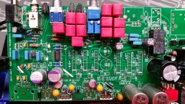
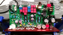
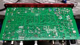
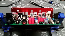
Steps 8, 9, and 10 done. Pics below.
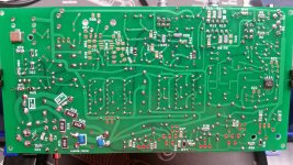
On the bottom of the board, you can see I jumper-ed across attenuation resistors (R31 and R32). I want to start out at full power, and if I don't need the full voltage swing, I'll remove the jumpers to decrease each gain stage by 1/2 and put it back to how it was before. (This was suggested by agdr a few posts ago).
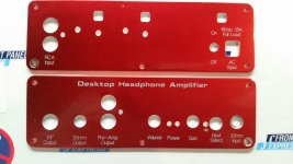
I also posted a pic of the panels as they came back from Front Panel Express. The quality on the etching and cuts is phenomenal. There's a plastic film on them which reflected weird in the photos (the white-ish spots), the panels came back with no scratches. For anyone curious, these are the red panels from the box enclosure with a grey letter filling... probably should have just left them with no fill and saved a couple bucks. I wanted a pic before I ruin these by drilling my own hole for an extra push button DPDT. 🙄
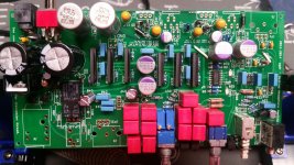
Speaking of the extra push button DPDT, you can see it in the overhead view where all the white wires are near the front. And in the front view, it is the upper left thing just "floating" in the air not attached to the board. It seams this switch is going to work out really well and mount in the upper left of the front panel.
Tomorrow is testing; for now... sleep 🙂
Steps 8, 9, and 10 done. Pics below.
On the bottom of the board, you can see I jumper-ed across attenuation resistors (R31 and R32). I want to start out at full power, and if I don't need the full voltage swing, I'll remove the jumpers to decrease each gain stage by 1/2 and put it back to how it was before. (This was suggested by agdr a few posts ago).
I also posted a pic of the panels as they came back from Front Panel Express. The quality on the etching and cuts is phenomenal. There's a plastic film on them which reflected weird in the photos (the white-ish spots), the panels came back with no scratches. For anyone curious, these are the red panels from the box enclosure with a grey letter filling... probably should have just left them with no fill and saved a couple bucks. I wanted a pic before I ruin these by drilling my own hole for an extra push button DPDT. 🙄
Speaking of the extra push button DPDT, you can see it in the overhead view where all the white wires are near the front. And in the front view, it is the upper left thing just "floating" in the air not attached to the board. It seams this switch is going to work out really well and mount in the upper left of the front panel.
Tomorrow is testing; for now... sleep 🙂
Attachments
- Home
- Amplifiers
- Headphone Systems
- A version of an O2 Desktop Amp (ODA)