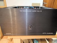
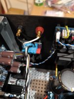
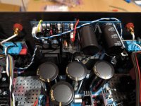
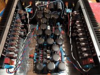
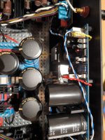
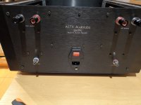
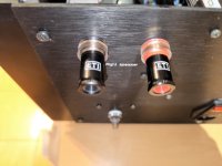
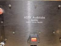
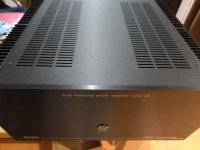
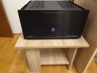
Finally finished a proper piece of amplifier, reference product from ASTX -- SA2014. On the bottom of the chassis 2 massive audio toroids 600VA, above each extreme filtration 80.000uF per channel. The amplifier also has a proper 400W/4Ohm and 200/8Ohm output. Grounding I did through two diode bridges. No hum or noise. Now I just need to save up for a big tower speaker Jenzen Illuminator. Sound Good 🙂
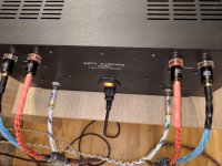
Source: PC/Tidal
DAC: SMSL MDA RAW 1
PREAMP: SMSL H400
Source: PC/Tidal
DAC: SMSL MDA RAW 1
PREAMP: SMSL H400
Attachments
-
 IMG_20241001_182158.jpg233.1 KB · Views: 196
 -
 IMG_20241001_182518.jpg313.6 KB · Views: 194
 -
 IMG_20241001_182532.jpg380.3 KB · Views: 194
 -
 IMG_20241001_182540.jpg336.9 KB · Views: 195
 -
 IMG_20241001_182546.jpg402 KB · Views: 250
 -
 IMG_20241001_182555.jpg583.4 KB · Views: 248
 -
 IMG_20241001_182815.jpg409.9 KB · Views: 236
 -
 IMG_20241001_182828.jpg410.7 KB · Views: 206
 -
 IMG_20241001_182841.jpg215.5 KB · Views: 199
 -
 IMG_20241001_182854.jpg240.8 KB · Views: 193
 -
 IMG_20241001_182909.jpg477.8 KB · Views: 180
 -
 IMG_20241001_183606.jpg291.7 KB · Views: 187
 -
 IMG_20241001_183834.jpg269.8 KB · Views: 176
 -
 IMG_20241001_184712.jpg364.8 KB · Views: 181
 -
 IMG_20241001_184726.jpg382.4 KB · Views: 195


So wow I finally decided for SA2015 V-Mosfet (with IRFP). The first set from astx is already at home.

I will take another one at the beginning of December, I decided for a 4-channel bi-amping amplifier. Again it will go into 5U modushop box, 2x 500VA toroid and extreme filtration 4x 33.000 uF per channel (2 amplifiers) 😉
Today I was working on the heatsink support plate, tomorrow I will check the spacing and send it to production... (200x150x10 mm/ black elox)
Hi Toni, I see your SA2023 is almost finished and looks fantastic👍.
Are you ready for the SA2025 ?😉
Maybe you already have sufficient amps, if so then I would still like to kick a few ideas around, if you are interested.
Basically I would like to develop the switch mode rail version of Class H, sketched out earlier in your thread >here<
I did more development on it, to use a proper comparator and FET driver IC, but became very busy at work and had a break.
Now work is not so busy and I can look at it once more.
It already simulates pretty nicely but now I look at it with fresh eyes and have a few new ideas.
The principle benefit is that the efficiency of switch mode means it all runs much cooler, so there is less need to parallel transistors, so it all becomes much simpler.
And less expensive! As you noted, the SA2023 is not a cheap amplifier🙂
The sims show just one switch FET per rail is possible.
The linear amplifier could maybe be a FET too.
Did you use multiple BJTs in the SA2023 for thermal reasons or because of the fall in Beta at maximum current?
FETs don't have the Beta problem, of course, and it looks feasible to reduce to just one per rail too.
If it was thermal then I noticed there are now Aluminium Nitride thermal pads that look to have spectacular performance.
In any case, nice to see you in such fine form with beautiful work, and nice that I now have the time to do a bit more on DIYaudio.
I just need to buy a new computer in the next few days to set-up with all the audio soft and hard ware.
(Have a new E2x2 interface and MicW M215 measurement condenser microphone.)
Best wishes
David
Attachments
Dear Dave,
nice to hear from you! Many thanks!
Absolutely - man can never have enough amplifiers ... 😆
Beta maximum current as it is a 2stageEF. As a positive side effect it reduces also THD+N.
Now I have to dust off my CNC machines and do some machining for the aluminium heatsinks, top and back front. Sides are made using acrylic glass 30% transparent.
The electronics is tested and waiting just for a case.😉
Have fun,
Toni
nice to hear from you! Many thanks!
Are you ready for the SA2025?
Absolutely - man can never have enough amplifiers ... 😆
Did you use multiple BJTs in the SA2023 for thermal reasons or because of the fall in Beta at maximum current?
FETs don't have the Beta problem, of course, and it looks feasible to reduce to just one per rail too.
Beta maximum current as it is a 2stageEF. As a positive side effect it reduces also THD+N.
E2x2 and MicW is a very nice setup. (I own an ESI Amber1 in combination with a Beyerdynamic MM1 - included is a file with mic correction data - which does the job for "ARTA" or "roomeqwizard" but is also very good for Dirac-Live measurements for my Denon AVC-A1H.)Have a new E2x2 interface and MicW M215 measurement condenser microphone
Now I have to dust off my CNC machines and do some machining for the aluminium heatsinks, top and back front. Sides are made using acrylic glass 30% transparent.
The electronics is tested and waiting just for a case.😉
Have fun,
Toni
Wonderful to have a positive response!
Your amp will look fantastic, and I will take a little while to be ready, so very well timed.
(Beta fall off at around 6 amps, maybe 18 or 20 amps for peaks into 3 ohms, so 3 devices or 4 to be conservative and reduce THD+N)
Since FETs don't suffer from Beta fall-off, it should be possible to just use 1.
Even 20 amps with, say 10 volts across the device, is within the SOA of the IXYS FETs.
Probably a little more crossover distortion (no sims until new machine), but simpler circuit and mechanics for sure.
What do you think?
Have you tried FETs as the OP transistors?
Best wishes
David
Your amp will look fantastic, and I will take a little while to be ready, so very well timed.
Ok, that's what I expected from back-of-an-envelope calculation.Beta maximum current as it is a 2stageEF. As a positive side effect it reduces also THD+N.
(Beta fall off at around 6 amps, maybe 18 or 20 amps for peaks into 3 ohms, so 3 devices or 4 to be conservative and reduce THD+N)
Since FETs don't suffer from Beta fall-off, it should be possible to just use 1.
Even 20 amps with, say 10 volts across the device, is within the SOA of the IXYS FETs.
Probably a little more crossover distortion (no sims until new machine), but simpler circuit and mechanics for sure.
What do you think?
Have you tried FETs as the OP transistors?
Best wishes
David
I have simulated using FETs as OP transistors, but heftiy oscillations I couldn't get fixed. The idea was then to take "slow" bjt and let the tracking do the fast FETs. After fixing some small oscillation problems the SA2021-NCH mastered the high power tests.
BR, Toni
BR, Toni
Greetings everyone,
Hope you're all doing fine.
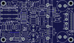
Here's my (cloned) version of SA2014 VAS based on the latest schematic and PCB layout available by Toni,
Didn't test it yet
I had to remake it because I wanted to build this on single layer PCBs for my use.
PS. I'm no professional/skilled PCB designer, I know there are tons of mistake here, recommendations are always welcome 🙂
Hope you're all doing fine.
Here's my (cloned) version of SA2014 VAS based on the latest schematic and PCB layout available by Toni,
Didn't test it yet
I had to remake it because I wanted to build this on single layer PCBs for my use.
PS. I'm no professional/skilled PCB designer, I know there are tons of mistake here, recommendations are always welcome 🙂
Attachments
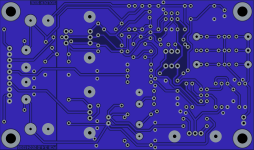
Nice work, here the (untested) official single sided version of the SA2014 input stage in the same pcb size as the double sided variant. The output stage still needs to be done as single sided pcb
The CCS mod is highly recommend!
BR, Toni
The CCS mod is highly recommend!
BR, Toni
Attachments
-
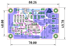
 sa2014_input_vas_stage_schematic.png538.6 KB · Views: 215
 -
sa2013_input_vas_stage_singlesided_pcb.pdf419 KB · Views: 88
-
 sa2013_input_vas_stage_singlesided_pcb_top.png1.3 MB · Views: 205
 -
 sa2013_input_vas_stage_singlesided_pcb_bottom.png1.1 MB · Views: 202
 -
sa2013_input_vas_stage_singlesided_pcb.zip131.1 KB · Views: 76
-
sa2014_input_vas_stage_schematic.pdf52.2 KB · Views: 95
Last edited:
Thanks for your response Toni!
I'll etch and test it and I will add the CCS mod in the VAS side PCB for me.
I'm halfway done laying the output stage on a single side,
Should I really skip the "opt" parts or you recommend adding them on? If so how can I find their values?
I'll etch and test it and I will add the CCS mod in the VAS side PCB for me.
I'm halfway done laying the output stage on a single side,
Should I really skip the "opt" parts or you recommend adding them on? If so how can I find their values?
Parts with "opt." are for development only - do not populate them. Use only "TMC" compensation scheme. R8=68R, C9=68p, C11=820p, R23=470R
If the amp oscillates (test with square wave and scope.), try to increase C9 to 82pF or 100pF.
If the amp oscillates (test with square wave and scope.), try to increase C9 to 82pF or 100pF.
Last edited:
Yes, connected. It is a buffered feedback current mirror. D. Self named this current mirror "EFA" (Emitter Follower Added) in his book APAD 6, p133
Last edited:
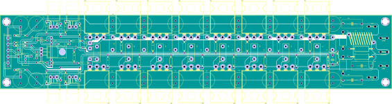
Single sided (untested) version of SA2014 output stage.
Tried to do with as less jumpers as possible, it's only 2 jumpers now because of the removal of "opt" components else there'd be much more.
Need to do a lot of optimisations to the layout before sending to fab.
Thinking about moving zobel network part to speaker protection board.
Any suggestions are always welcome 😀
Attachments
- Home
- Amplifiers
- Solid State
- 2stageEF high performance class AB power amp / 200W8R / 400W4R