In that case I would use the TTC5200 and TTA1943, I'll order them alongside TTC011B from MOUSER.Ad Q1: using NJW0302G and NJW0281G would require a redesign of the VAS/Output stage. I never got it stable using > 4 pairs MJW3281A and MJW1302A. The TTC5200 and TTA1943 are inexpensive and 8 pairs guarantee you lowest THD and highest reliability.
You are right, I understand now that gain is critical here. Its EF2 not EF3 output stage.Ad Q2: Using MJE15032 & MJE15033 is a no go. They have to low hFe and are too slow. You need the high gain of 2SC4793 & 2SA1837. Note: It's a 2 stage EF output.
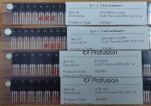
What do you think about these devices I have, they are the clones of 2SC4793 & 2SA1837, can we use them?
https://www.keccorp.com/en/product/product_view.asp?idx=354
Thanks & Regards,
Arshad.

KTC4793/KTA1837 is fine. I ordered 50/50pcs from Profusionplc. Easy to find pairs, with Hfe=140-150...
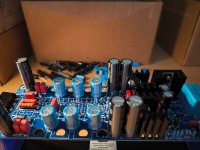
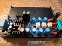
Friends I'm about to finish SA2015, so far the first channel is almost done, ...I'm still waiting for the delivery of the ceramic pads to start testing! Several of you in the past have addressed in what order to solder capacitors, power mosfets and power resistors.
For me it's probably best like this:
For me it's probably best like this:
- Capacitors 330uF
- Power mosfets
- Power resistors
Attachments
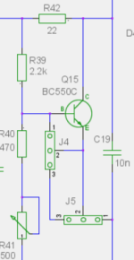
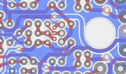
See attached picture: J4 unused, J5 connection from pin 1 to pin 2 (red line).
The pcb is a bit modular. For the SA2016 L-Mosfet the bias transistor Q15 is a BC550C so the big hole right stays empty. The BC550C needs to be soldered on the SOLDER side mirrored on the vertical axis. A hole in the heatsink about 1-2mm deep for the BC550C top is recommended. Add some thermal compound into this hole to get a good thermal connection for the BC550C. Similar to the SA2015 IRFP/MOS pcb.
BR, Toni
Attachments

Last edited:
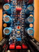
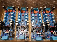
4 modules ready for mounting power mosfets. I'll probably get to that next week, ...I have a working weekend ahead of me 🙄
Maybe you are asking the question why 4 modules? My DIY path leads to active 3 way speakers.
1, active crossover - 2x miniDSP 2x4 HD
2, tweeter, mid - SA2015 (140W)
3, bass - SA2016 (300W)
Maybe you are asking the question why 4 modules? My DIY path leads to active 3 way speakers.
1, active crossover - 2x miniDSP 2x4 HD
2, tweeter, mid - SA2015 (140W)
3, bass - SA2016 (300W)
Attachments
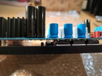
what's your process for coiling those output inductors? they're perfect!4 modules ready for mounting power mosfets. I'll probably get to that next week, ...I have a working weekend ahead of me 🙄
Maybe you are asking the question why 4 modules? My DIY path leads to active 3 way speakers.
1, active crossover - 2x miniDSP 2x4 HD
2, tweeter, mid - SA2015 (140W)
3, bass - SA2016 (300W)
Hi Toni,
May I know the reason on your preference to use IXYS IXTH80N20L/IXTH48P20P for the higher rail SA2021-NCH?
(Except of course that it worked on your bench testing)
Is this part specifically designed for this amp (like TTC5200/TTA1943 for lower rail), or is there alternate MOSFET I could use?
regards,
Roland
Have a look at the datasheets. Low gate charge, wide linear power range, very high power dissipation per device. And very good simulation models designed by dave zan.
FQA40N25Hi Toni,
May I know the reason on your preference to use IXYS IXTH80N20L/IXTH48P20P for the higher rail SA2021-NCH?
(Except of course that it worked on your bench testing)
Is this part specifically designed for this amp (like TTC5200/TTA1943 for lower rail), or is there alternate MOSFET I could use?
regards,
Roland
fits better to the P CH i guess. ..........and still available at mosuer
- Home
- Amplifiers
- Solid State
- 2stageEF high performance class AB power amp / 200W8R / 400W4R