Dedicated to our DIYAUDIO electronic Guru @Dave Zan: Your Idea which helped to materialize the high end power beast SA2021-NCH rocks!
Wish you where here listening with me!
Have fun, Toni
Wish you where here listening with me!
Have fun, Toni

SA2021-NCH will get a LED-VU meter .... remote controlled ...
Attachments
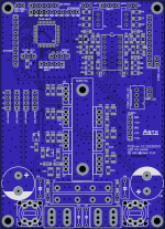

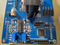
There are 3 PWM channels which controls RGB led stripes in the inner to show the electronics.
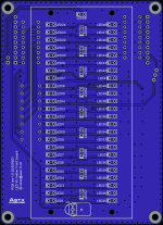
The LED bar can be controlled to display classic VU meter, peak only, VU and peak hold, difference, difference and peak ...
The VU scale is from +6dB down to -32 dB in 2dB steps and showing the last 4 steps in 4 dB steps down to - 48 dB.
The LED's are multiplexed 2000 times per second in 6 groups which is about 166 Hz per LED.
Attachments
Last edited:
SA2021 LED VU: Looks like it would be soon ready for production ...
Remote control works. Mode switching works, changing amplifiers inside backlight color and brightness works (can be seen at the end of the video).
VU modes:
For "LED_MODE_OVERLOAD_ONLY" it can be configured, that the display only works if a minimum dB level has been reached. So normally the VU meter is dark, but just be4 clipping occurs, the peak hold starts glowing.
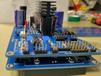
The 2x24 VU LED's are multiplexed in 6 x 8 matrix with a 2000 ticks task which gives a comfortable 166Hz per LED. No ghosting and no flickering. The brightness of all LED's is equal during all modes.
The board drives a 3 color RGB LED stripe which lights the inner of SA2021 tower. The brightness is not adjusted using multiplexing, instead it uses 3 PWMs (160kHz base freq.) to generate a 0-5V "DAC" output to generate a 7 - 12V voltage for the LED stripes.
Have fun, Toni
Remote control works. Mode switching works, changing amplifiers inside backlight color and brightness works (can be seen at the end of the video).
VU modes:
Code:
        LED_MODE_DARK,
        LED_MODE_BAR,
        LED_MODE_BAR_AND_PEAK,
        LED_MODE_PEAK_ONLY,
        LED_MODE_DOT_ONLY,
        LED_MODE_DOT_AND_PEAK,
        LED_MODE_OVERLOAD_ONLY,
For "LED_MODE_OVERLOAD_ONLY" it can be configured, that the display only works if a minimum dB level has been reached. So normally the VU meter is dark, but just be4 clipping occurs, the peak hold starts glowing.
The 2x24 VU LED's are multiplexed in 6 x 8 matrix with a 2000 ticks task which gives a comfortable 166Hz per LED. No ghosting and no flickering. The brightness of all LED's is equal during all modes.
The board drives a 3 color RGB LED stripe which lights the inner of SA2021 tower. The brightness is not adjusted using multiplexing, instead it uses 3 PWMs (160kHz base freq.) to generate a 0-5V "DAC" output to generate a 7 - 12V voltage for the LED stripes.
Have fun, Toni
Attachments
Last edited:
Attached a video from the original project from 2011.08.04. Made homebrew single sided pcb's. It was a good learning project.
For today this is now enough retro electronics ...
I'm glad, that this long running project is now finished (first prototype was from 2011 and the basic PIC software idea too).
BTW: both videos are not "lipsync" - in real life the VU has a very fast reaction time and a perfect peak detection.
Have fun, Toni
P.S.: pcb's for the new (!) project are on stock if one is crazy enough to build this VU 😉
Attachments
Last edited:
Interesting project.
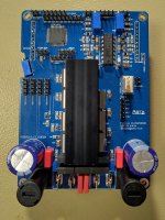
I see an electrolytic capacitor is used in the feedback path.
Is it really beneficial to use big and expensive polypropylene capacitors for just dc-blocking at the input then?
Can't a single and small polyester type be used here?
An electrolytic capacitor with the same capacity would improve the power-on dc behaviour...
Last edited:
PP is lowest distortion. To achieve the same with a lytic we would need a 200-500uF lytic. But I wanted to limit the bandwith below 4Hz.
The 470uF lytic (sometimes bypassed with a PP) in the feedback path is for DC offset to be minimized.
The 470uF lytic (sometimes bypassed with a PP) in the feedback path is for DC offset to be minimized.
These questions are already answered e.g. in the APAD 6th edition from D. Self.
Have a look at page 297 ff
Have a look at page 297 ff
Spacecraft don’t use electrolytic capacitors because they aren’t able to be used in a vacuum due to out gassing and short lifetime. Tantalum caps or MLCC’s are used instead.Transistors should last "forever" - only "electro migration" problem operating the parts near limits will kill them. Maybe the Voyager space probe has no lytics on board to stabilize the on board voltages (offered by nuclear batteries). This may explain the reliability of the electronics.
SA2014 may get problems after another 20000 - 50000 hours of operating when some lytics going the path to death (dry out). But thats maybe beyond my personal lifetime and it is very likely that I can never report this event to the DIY community 🤣
Have fun, Toni
P.S.: The EVVO A1837/C4793 are looking not to be a good replacement for Toshiba A1837/C4793. The Unisonic (UTC) or KEC variants are closer to the original
Link to pictures for SA2014 and SA2021-NCH
SA2014 - 4 Channel - pictures
SA2021 - NCH - picture series 1
SA2021 - NCH - picture series 2
SA2021 - NCH - picture series 3
SA2021 - NCH - picture series 4
SA2021 - NCH - picture series 5
SA2014 - 4 Channel - pictures
SA2021 - NCH - picture series 1
SA2021 - NCH - picture series 2
SA2021 - NCH - picture series 3
SA2021 - NCH - picture series 4
SA2021 - NCH - picture series 5
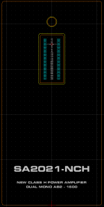
Now the SA2021-NCH has it's own VU-Meter and retro disco lights effects. (VU has a -40 to +6dB range; about 1/40000)
Of course all effects can be changed using a remote control.
The next days the engraving will be colored in different blue versions...
Stay tuned, have fun, Toni
Of course all effects can be changed using a remote control.
The next days the engraving will be colored in different blue versions...
Stay tuned, have fun, Toni
Attachments
Last edited:
Thx, the VU display was a long journey to find the best way for the backlight. The VU display has three stacked film sheets behind the acryl glass:
1) a professional made laser film mask (all numbers and the led/RC square)
2) a home laser printed colored film using Zweckform 3491 film. (this gives light blue color for led's and dB scale, orange and red/magenta overload led's)
3) a home laser printed b/w film mask using Zweckform 3491 film
4) a home made cnc machined 3mm thick 25% grey acryl glass on front
The frame which glues this parts together was 3D printed in PETG.
Case internal lights: The RGB LED stripes are linear powered (7 - 12V) to avoid HF noise. Three 166kHz PWM pin's from MCU are used to generate analog DAC outputs to control the RGB voltages.
Firmware (only hex!), pcb's, stl files and PDF's for film printing are available - just send a PM. The remote control is a NEC clone (see project SA2022 Preamplifier - link in post #1)
Have fun, Toni
Last edited:
- Home
- Amplifiers
- Solid State
- 2stageEF high performance class AB power amp / 200W8R / 400W4R