
I often visit your site. Thank you for giving me a lot of interesting information. I just wanted to repeat your payment for my DAC. Please share the drawing of the CXD1244-TDA1541 board in any format. If you need payment, let me know in private messages. Thanks!
It is VAC nickel laminations "Mumetall-A" type. Don't know the type, You can determine by measuring inductance with 2-3 different turn values.Anybody has any idea what lamination material is this? Dimensions: M42, thickness: 0.1 mm, gap width: 0.2 mm. I am building a pair of 1:16 transformer from it. I will publish the measurements if ready.
The gap is fixed, so the gap int opposite direction will be somewhat of 1/3 (from my measurements and calc) if You are using it withhout any DC magnetization...
I have almost probaly the same laminatons. That is what I am talking about...
...
If You have the wire for HF one with silk jacket and multiplied enamelled wires inside - good for windings
...
If You pulled them out from some wquipment, maybe it was the chance that the cores are magnetized with DC from fault equipment. Stack and combine them 1 from each other core into 2 cores for the start.
Last edited:
About core linearity:Yup.
So as I noted, the Mothers of Invention at work.
IF VAC Vitroperm 500F really is competitive with 80% Nickel permalloy (and nothing in the Datasheet on VAC's would remotely ever make me suspect such a thing in a million years) that would be great.
Looking forward to see something I can relate to this:
View attachment 1376414
So test with Zsrc 150R and 20/30/50Hz at -40dBu to 0dBu.
Thor
Well remembered. Recently I finished something:
https://www.diyaudio.com/community/...-audio-volume-13.308860/page-108#post-7770174
#post 2141:
Harmonic distortion vs frequency (PWM9, loud mode, -1dB signal): (-1dB of digital signal generation feed🙂
Balanced. My test gig is unbalanced, so I summed the output from this DAC using a nanocrystalline trafo. Notice the constant HD vs frequency. Rsource = ~800R+10µF (the 2 output R in series, plus 2x 20µF caps in series). Rload: some shielded wire // 50k.
High order HD raising at near 20kHz is from my gig ADC. Some across the band are from the DAC being measured. This DAC have ~0.015% of THD at 0dB.
Most of this distortion are coming from the DAC. The core ar not adding almost nothing to low frequencies here, and some reaction with coupling cap, rotating the 3H, is seen here.
Is not too shabby, although the analog signal here is less than 300mV RMS. Reducing the Rsource we can safely arrives at some required level of HD at 20Hz with more amplitude. ( I deduce).
Have a lot of potential. So, I think that the proof #1 is there.
Now I'm curious about something: some cores have constant HD when we reduce the LF signal. now I want to know if nanocrystalline reduces or are constant as the other materials. Ie, I need some noise-free time to measure fixed frequency vs amplitude. Becuase I also consider this important for the choice. Perhaps MORE important. Since not make sense a low HD at 0dB if the core have some hysteresis and eddy currents playing havoc at low levels.
I need to ask to the factory where I worked about the specific grade they used for it. Only I remeber they used the same from the "miraculous" tranformer current measuring nA at 60Hz.
All of this is NOT a criticism against old great cores like you and people here are mentioning here, and also is not to have a blind faith on the modern thing and throw in the window the old options (like the current human disease ;-) is more a kind of "great, finally some more options"...
BTW. If I worked in a factory using fine nickel cores, I will used it certainly...
LATE EDIT: for my DAC with PCM1704, I'm relaxed a little about the HD and make it with less turns (a lot less), achieving more than 0.07%HD at 20Hz. I not worried too much due to know low hysteresys distortion of this core.
Last edited:
probably in parallel addition to input R on the card or computer...Rload: some shielded wire // 50k.
.
Give some basics of the transforemer You used? Lp, Lleakage, Cprim, Rdc prim sec. etc..?
You said already that it was 800ohm cca output.
.
Also OCM1794 has current out with Idc of about -6.2mA. How did You manage that, with Couplping C to transformer?
.
Thanks 🙂
Most of this distortion are coming from the DAC. The core ar not adding almost nothing to low frequencies here, and some reaction with coupling cap, rotating the 3H, is seen here.
Interesting. But a DAC with ~ -80dB H3 can hide a multitude of sins...
Now I'm curious about something: some cores have constant HD when we reduce the LF signal.
They do not. The seem to have a "shelf" before HD falls off again.
now I want to know if nanocrystalline reduces or are constant as the other materials. Ie,
Without knowing the material formulation I think the rest is secondary. There certainly are high nickel nanocrystalline cores.
I need to ask to the factory where I worked about the specific grade they used for it. Only I remeber they used the same from the "miraculous" tranformer current measuring nA at 60Hz.
78% Ni, 17% Fe, 5% Mo NC perhaps?
more a kind of "great, finally some more options"...
I'll be the first to jump for joy. This whole core issue has given enough headaches.
LATE EDIT: for my DAC with PCM1704, I'm relaxed a little about the HD and make it with less turns (a lot less), achieving more than 0.07%HD at 20Hz. I not worried too much due to know low hysteresys distortion of this core.
So -63dB HD.
Thor
Yes, the 50k is the total load (100k pot for the gig //~50k card input). Plus some cable capacitance.probably in parallel addition to input R on the card or computer...
.
Give some basics of the transforemer You used? Lp, Lleakage, Cprim, Rdc prim sec. etc..?
You said already that it was 800ohm cca output.
.
Also OCM1794 has current out with Idc of about -6.2mA. How did You manage that, with Couplping C to transformer?
.
Thanks 🙂
The transformer are one unintended for this operation. I created it years ago (2010) for using 1:5 or 1:2+2 (1:5 in auto-former mode).
In this DAC, I used only due to the fact of my gig being unbalanced. So, I feed 2 "secondaries" (now primaries), one with each DAC phase. Not ideal due to unequal parasitics***, but suprisingly, resulted flat response and distortion to more than 20kHz. And the good 20Hz result, since it have enough turns to work with higher signal before it saturates.
A note about the 2 primaries: each half is driven by 400R+20µF. The signal are see as "series" (each PRI receives 1/2 of the signal), so I analyzed the source being as 800R, for the total primary.
***Is not a ideal trafo since it only have 3 layers; the center layer is the output for the measurements, without any electrostitic shielding, only with normal inter-layer insulation. I think it will destroy the HF response too early, but at least past 20kHz, have good behaviour, and is flat to more than 20kHz in response. Since it are using as 2+2:1, the signal at the plots in the orignal thread are somewhat low (no preamp at this time).
I can measured it rdc (270R for inner PRI; 360R for outer PRI, 150R for the SEC - PRI/SEC as seen by this application), but Lp will be only indirectly; my meter don't comes even close to it's actual inductance. Capacitance I forget to take note...
Too bad I stopped to explore signal trafos when I left the trafo company I worked. And it was a 3 years only experience...
I just ask my ex-boss that worked for the company. He was in charge of cores, and perhaps he remember (since I lost my detailed notes).78% Ni, 17% Fe, 5% Mo NC perhaps?
The CPLD is available at LCSC and current, so could go onto a PCB made by JLCPCB at a cost.
LCMXO2-256HC-4SG
So, I downloaded Lattice Diamond (no need unless you want to compile yourself) and had a look (open the files with Notepad++ to save on the Scarborough Fayre).
I don't speak Lattice FPGA or Verilog, but the code seems pukka AFAICT...
The code is simple enough. If I get moments I shall penetrate this mystery deeper.
But I'm reasonably confident that the FPGA will do what it says on the tin. No more and no less.
It appears the MCK connection is actually ignored.
BCK is divided by 4 to generate output BCK and the input and output buffers are 16 Bit.
Send L/R 16 Bit input into the input buffers. Clock out 16 Bit from the output buffer, set LF and load the now in the input buffer into the output buffer, clock out these bits and refill the input buffer from IIS, rinse, repeat ad infinitum. Bit of extra logic to massage LE and invert MSB.
Pretty much what I had in mind for my conceptual more pedestrian discrete logic version. No more, no less.
Thor
Hi all, just wanted to note that I’m following this thread with great enthousiasm, learned and laughed a lot already 🙂 was hoping to piggyback on and help finance the PCB once it comes to production by buying one (or more).
I’m currently using the TDA with resistor IV and tube amplification and about to embark on going for balanced in simultaneous mode. Even in Veroboard stage I quite like the sound, so a pro board like describe here can only improve things.
500 pages didn’t seem to result in a preference for paralleling of TDAs or a balanced mode, is that still on the table, ie could the boards be used / designed in such a way that they are stacked? Don’t want to open another 200 pages long box of worms, but I’d be happy to buy a few more PCBs if that was an option 🙂
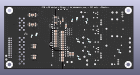
I putted the 4 layers core pcb proto in production yesterday. It will be tested first and if measuring good, it will permitt also to make some tests as theories and measurements poped up a lot since 30 pages.
It shoud take one month between now and the populated and tested boards according the time free for the testers to check it, experiments their ideas (different decoupling, etc). It is a proto for experiments : he has an header (JLSOUNDS lab for sim mode) and SMA/UF-L inputs for testing all sort of digital front ends. With and w/o active clock DEM synchro. Versatile board w/o trade offs for signal routing.
It is SE though not balanced 15cmx7cm. so balancing at the output of the I/V stage migth be the best option if noone has planned to make a balanced one.
Maybe the last 30 pages is worthing a read as the idea begun in june or july with the come back of Thorsten Loesch in the bar.
Attachments
Last edited:
Hi @diyiggy ultimately my set is single ended, but I was intrigued by the potential noise cancelling in balanced mode and there seem to be a lot of respected and knowledgable people on this thread hence my interest.
I actually have a different post in which I asked for advice on a differential amplifier to "unbalance" the balanced signal 🙂
In any case, if you're at the proto pcb stage already please ignore my previous comment and leave that box of worms untouched. I'd still be keen to purchase a PCB once it's in production though! Again awesome to read and see all the collaboration here!
Way back we did a comparison test with true balanced ccd/pre/power amp against the single ended cd/pre/power amp & we all agreed that balancedHi @diyiggy ultimately my set is single ended, but I was intrigued by the potential noise cancelling in balanced mode and there seem to be a lot of respected and knowledgable people on this thread hence my interest.
I actually have a different post in which I asked for advice on a differential amplifier to "unbalance" the balanced signal 🙂
In any case, if you're at the proto pcb stage already please ignore my previous comment and leave that box of worms untouched. I'd still be keen to purchase a PCB once it's in production though! Again awesome to read and see all the collaboration here!
sound cleaner you hear deeper into the soundstage etc but single ended sounded better overall to the ears off course measurements says otherwise.
Me thinks for the TDA we should not be too dogmatic about noise, just quiet enough will do.
Cheers
Two TDA is more a challenge layout wise. Making it with a two layers pcb with ground tracks IS a bad idea. And a 4 layer will be always quieter (for a standaloneic as well).
So one TDA and balanced output stage is imho where to go if having balanced input pre or amp.
OT SE to balanced perhaps ? op1633 is a pretty good sounding op amp for that task, you should have pain to do quieter.
So one TDA and balanced output stage is imho where to go if having balanced input pre or amp.
OT SE to balanced perhaps ? op1633 is a pretty good sounding op amp for that task, you should have pain to do quieter.
Way back we did a comparison test with true balanced ccd/pre/power amp against the single ended cd/pre/power amp & we all agreed that balanced
sound cleaner you hear deeper into the soundstage etc but single ended sounded better overall to the ears off course measurements says otherwise.
If we for a moment ignore dealing with earth loops and related issues in audio, where balanced connections are clearly superior, which may sway both objective and subjective tests, once we level the playing field, "balanced" circuit in the absolutely BEST case are 3dB more noisy and have 3dB more odd order distortion than the same circuit in SE.
We can combat noise rise by doubling up input devices, so we now have 4 input devices for SE's one. Of course, if made the SE circuit with 4 Input devices we would lower noise by 6dB.
Same on increased odd order distortion. We can take extra measures to compensate, but apply the same amount of devices and same improvements to SE and SE is again ahead.
There are some possible win's in "Balanced" but not many, for low....line level audio and there are a lot of losses.
So don't expect "magic" from the word "balanced" (of from any other "magic" audio be it "Class A", "Non-OS", "Asynchronous", "Digital", "PCM", "DSD", "Analogue", "Simultaneous", "Super Capacitor", "Battery", "Nichion Muse", "Elna Silmic", "C0G/NP0", "Teflon" etc, et al). Audio is not Magik, it is magic, that is, an illusion and fully ameanable to rational analysis and understanding.
Magical thinking is counterproductive.
Two TDA is more a challenge layout wise. Making it with a two layers pcb with ground tracks IS a bad idea. And a 4 layer will be always quieter (for a standaloneic as well).
Yes, layout, extra complexity etc. have a large "debit" column in the ledger.
And the "credit" column is surprisingly bare.
So one TDA and balanced output stage is imho where to go if having balanced input pre or amp.
My take as well.
OT SE to balanced perhaps ? op1633 is a pretty good sounding op amp for that task, you should have pain to do quieter.
Trivial, 3 transistors... More HD, but still ok next to most other stuff.
Thor
I'd like to add "nickel".... 😉So don't expect "magic" from the word "balanced" (of from any other "magic" audio be it "Class A", "Non-OS", "Asynchronous", "Digital", "PCM", "DSD", "Analogue", "Simultaneous", "Super Capacitor", "Battery", "Nichion Muse", "Elna Silmic", "C0G/NP0", "Teflon" etc, et al). Audio is not Magik, it is magic, that is, an illusion and fully ameanable to rational analysis and understanding.
I'd like to add "nickel".... 😉
I'd like to "Amorphous" and "Nanocrystalline" then.
Non of this is any way meaningful in itself. Context, application and requirements are everything.
My point about 80% nickel alloys is simply that they have a certain magnetic behaviour that is desirable for low level transformers.
NOTE, it is all about the outcome.
And so far my objection is simply that nobody demonstrated comparable or better outcome with anything else.
Just like the Chupacabra and Bigfoot, absence of proof for their existence is NOT proof they do not exist (or that nothing better than 80% nickel alloys exists), but I will remain sceptical regarding their existence (that is, I will not exclude their existence, but I will not "believe" in them) until shown evidence I accept as reliable).
Thor
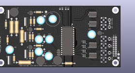
Nice job @diyiggy
Can we see what you've done with layer 2 and 3?
@ThorstenL
Can you please recommend a good high nickel core 1:1 OT for balanced output? From your tests what was the lowest you saw H3 @ 20Hz and 1khz? I need it below -100dBc @1khz
All I want to do is drive a tube grid (ECC88 for example), with an RIV of 13R for both DAC - and DAC+
Cheers
Last edited:
Can you please recommend a good high nickel core 1:1 for balanced output? From your tests what was the lowest you saw H3 @ 20Hz? I need it below -100dBc @1k
All I want to do is drive a tube grid (ECC88 for example), with an RIV of 13R for both DAC - and DAC+
This needs a shielded low impedance transformer. A 150+150 : 150+150 could work.
I'm not really aware of anything OTS I have tried, it's just an application I never even considered. It's also not something I have seen among commercial
Maybe this:
https://www.jensen-transformers.com/wp-content/uploads/2014/08/jt-mb-c.pdf
https://www.fullcompass.com/prod/26...t-mb-c-jensen-microphone-bridging-transformer
It's a "mic-splitter" 150R : 150R
As we drive the transformer from 26R as opposed to 150R we can expect ~ 5x lower THD than in the datasheet, so at -26dBu (TDA1541 Balanced into 150R primary) we expect perhaps 0.01% of Hz @ 20Hz or around -80dB. The 1kHz distortion at that signal level will be measured by AP2 very precisely as a minor tiny fraction of feck all, easily well below -100dB.
The datasheet shows for -20dBu 1kHz a THD&N of < 0.001% THD or < -100dB. with the lower source impedance etc. we might approach -120dB at -26dBu from 26 Ohm for 1khz.
Note, I never tried this transformer. At 100 Bux a throw it may be a much for an experiment.
Thor
- Home
- Source & Line
- Digital Line Level
- Building the ultimate NOS DAC using TDA1541A