Yes, I think it's a worthwhile cause! Maybe just because the decades long fallback of simple op amp/diode clipping in solid state amps lacks any real character. As you mentioned, a tube screamer into a tube amp isn't the same as a tube screamer going into a typical solid state amp. It would be interesting to design a very simple amp like the Fender Champ, one volume and one tone control but with soft limiting and bias shifting stages. using discrete transistors. Start from the basics and work from there.All of which means there may be much more interest in DIY builds of relatively simple analogue solid-state guitar amplifiers over the next year or two, as production shortages of commercially manufactured guitar amplifiers are expected to last at least that long
That's really impressive bmc0 , well done indeed!I decided to try to fit the anode characteristics of my solid state pentode emulator to data I extracted from the Philips EL34 datasheet rather than a SPICE model.

I look forward to hearing more about that.I suppose the question now is how the circuit performs in practice.
It's true there are audible differences between one pentode and another, and between true pentodes and beam power tubes. But those are much smaller than the differences between generic solid-state power amplifiers, and any kind of pentode.
Your circuit has curves so similar to a pentode, that I'd be very surprised if your circuit doesn't also sound very similar to a pentode. 🙂
My ears say clean tone (timbre, really) from a Fender Champ largely comes from the 6V6 output tube. That lovely clean tone largely goes away in otherwise similar Fender push-pull output stages using two of the same 6V6 tubes, presumably because of the cancellation of even harmonics.
Since you already have a good simulation of an output pentode, my suggestion is try a quick and easy listening test with just your SS pentode simulation, single-ended, driving a speaker. Use whatever is lying around for the preamp - a guitar EQ pedal is ideal, because you can quickly stick in a dip in the 600 - 800 Hz region, which usually makes a 6V6 sing it's clean tones even more sweetly.
Very nice work so far!
-Gnobuddy
If anyone is still reading, I have questions I hope aren't too naive about the original circuit. I'm having difficulty understanding how a guitar's "300mV (rms, peak, p-p?)' input signal can break-over or overcome the 2x Si diodes plus the 750mV Vref on the positive swing by itself. And if 300mV means peak then that's a hot pickup a la hum-bucker type vs. single coil. And, what of the negative input swing..? How does that work.? Btw, I'm always looking for empirical test results for the actual incremental impedance change of a 12ax7 grid driven beyond 0Vgs. If you know of such a study please reply with a link.
Could you please clarify what you mean by "original circuit"? I'd like to help, but with 14 pages of threaded posts to go through, I don't know which circuit you're referring to.I have questions...about the original circuit.
-Gnobuddy
incremental impedance change of a 12ax7 grid driven beyond 0Vgs.
Guitar Amplifier Overdrive
by Ulrich Neumann, Malcolm Irving
https://www.amazon.com/Guitar-Amplifier-Overdrive-Ulrich-Neumann/dp/132959665X
https://www.abebooks.com/9781329596658/Guitar-Amplifier-Overdrive-Neumann-Ulrich-132959665X/plp
An unexpected data-bit: it depends on brand!
I don't have direct measurements of a real tube, but I've attached some data generated using Adrian Immler's 12AX7.TSr4 SPICE model. The model is fitted to measured grid current data and should be reasonably accurate. The grid resistance is about 10kΩ @ Vgk=0V and about 4.2kΩ @ Vgk=0.5V.I'm always looking for empirical test results for the actual incremental impedance change of a 12ax7 grid driven beyond 0Vgs.
Attachments

Thank you both!
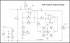
Gnobuddy asked what I meant by "original" circuit. The thread was split-off to another forum so I can't find it but I kept the URL of one image,
https://www.diyaudio.com/community/attachments/schem-png.1026803/
My questions above relate to this schematic.
Adrian Immler's name is mentioned in the original post..
Yes, I wish that >0V portion was expanded. Probably like snow flakes - no two exactly alike.I don't have direct measurements of a real tube, but I've attached some data generated using Adrian Immler's 12AX7.TSr4 SPICE model. The model is fitted to measured grid current data and should be reasonably accurate. The grid resistance is about 10kΩ @ Vgk=0V and about 4.2kΩ @ Vgk=0.5V.
That circuit is an old idea of mine. The circuit in this post should work better. I still haven't tried building it (working on other projects right now), but the simulations seem promising.Gnobuddy asked what I meant by "original" circuit.
The grid resistance continues to drop. Roughly 3kΩ@1V, 1.8kΩ@2.5V, and 1.2kΩ@5V. I can't imagine you'd ever see more than 2-3V Vgk in a guitar amp. At some point the current will destroy the control grid.Yes, I wish that >0V portion was expanded.
Very interesting data!...The grid resistance is about 10kΩ @ Vgk=0V and about 4.2kΩ @ Vgk=0.5V. <snip>
...The grid resistance continues to drop. Roughly 3kΩ@1V, 1.8kΩ@2.5V, and 1.2kΩ@5V.
I've suspected for some time that small amounts of grid current flow, in conjunction with the high output resistance of an electric guitar, might help to "squash" large positive-going signal transients at the start of each guitar note.
(This in turn leading to audibly less harshness than, say, an op-amp input stage in a solid-state guitar amplifier, which clips hard on input transients, rather than gently peak-limiting them.)
In a typical vintage Fender tube amp, quiescent Vgk is only around -1.4 volts. An e-guitar is perfectly capable of spitting out, for example, +/- 1.2 volt peaks, which would bring Vgk down to maybe 200 mV at the positive peaks.
The data you posted shows input resistance of a half-12AX7 has dropped to around 30 kilo ohms at that point.
This is more than low enough to apply some signal limiting to a guitar signal emerging from, say, a 500k volume pot set to half-resistance, which has a Thevenin source resistance of 125k.
A couple of days ago, I started a thread to discuss unwanted transient clipping and resulting audio harshness in SS guitar amplifiers, supported by LTSpice simulations. I've posted a link there to the data you presented here on 12AX7 input resistance vs Vgk.
If anyone is interested, that thread is here: https://www.diyaudio.com/community/...pping-in-solid-state-e-guitar-preamps.391513/
-Gnobuddy
Yes, very interesting but I must say that I can't find a source of empirically-measured electric guitar pickup voltage output that supports the view here that pickups "easily" or commonly send >1V peak or even 2.4Vp-p to the input jack of the amp. Here are several sources reporting measurements to the contrary
.
http://tomsguitarprojects.blogspot.com/2014/12/electric-guitar-output-voltage-levels.html
http://www.muzique.com/lab/pick.htm
https://sound-au.com/articles/guitar-voltage.htm#s3
Point being that you really can't it seems, drive that front-end 12AX7 into positive grid bias from the outside w/o using an external booster pedal which can deliver the overdrive V to create the soft clipping behavior. Just this kind of 12AX7 abuse (i.e. harmonics factory) is commonly done a stage or two or three or four deep into the amp's topology like cold clipping and/or voltage follower + grid violation like this thing if you can wade through the analysis:
https://www.ampbooks.com/mobile/classic-circuits/soldano-slo/
I am not a player and I have no gear but I'm a retired EE who's bored and needs a "project". My possibly "no use to anyone" project is to create a pedal which uses the Hollis opto-resistive "Flatline Limiter" to create high-gain but limited voltage (i.e. op amp will not rail) from raw pickup input coupled to an output level control and a series pot to control current output strength, mimicking the anode load R of the previous stage struggling with the >0V grid bias current in real life. This box will do this from the outside using level and strength constraints/control. And because it's so simple and small I plan to have a Dallas "RangeMaster" effect in the same box. That one's real famous and it not only enhances just the harmonic spectrum of the guitar (i.e. has no interest at all with the fundamental freqs as in, rolls them off) but also adds Germanium transistor cutoff distortion by biasing the Ge PNP near starvation. Depending on the transistor bias tweak you get asymmetrical distortion flavors with DC shift like the attached. Keeps me learning and busy...
Attachments
One diyAudio member posted a 'scope capture in a years-ago thread showing 10Vpp straight from his high-output humbucker.Yes, very interesting but I must say that I can't find a source of empirically-measured electric guitar pickup voltage output that supports the view here that pickups "easily" or commonly send >1V peak or even 2.4Vp-p to the input jack of the amp.
That was certainly an outlier - but other members have posted scope captures showing signals in the vicinity of 2 Vpp or more from their guitars.
All those are from people trying to get the biggest possible signal out of their guitars. Which may be representative of a rock guitarist high on adrenaline in front of a big audience. 😀
One of my guitars (Ibanez AS73), with stock factory pickups, will audibly overdrive the input stage of my '65 Fender Princeton Reverb (reissue). Just strumming chords at reasonable intensity, not trying to make the biggest signal I can.
What of subtler playing?
Well, the signal emerging from the first tube gain stage is certainly big enough to cause grid current flow in the second stage...and the source impedance is high enough to cause peak limiting there, too.
(100k load on a half-12AX7 gives you roughly 40k output resistance when you include the effect of the triode's internal plate resistance).
And, as you say, there are an almost endless number of little magic boxes that can go between the guitar and the input triode's grid, and amplify it sufficiently to cause grid current flow at the input triode.
(I've been using some of Rod Elliott's guitar signal data, in fact, in that other thread; a randomly picked one has 500mVpp at the start of the note. Noteworthy factoid: that particular signal is about 30 dB stronger at the start of the note, than at the end (3.75 seconds later).
If the note is to be audible 1 or 2 or 3 seconds after its start, something has to be done to squash the initial +30 dB level.
Incidentally, I'm not an EE, but have successfully imitated one, long enough to hold down a job as electronic design engineer until the company folded in the Dot Com collapse a couple of decades ago.
While there were things I didn't know that most EEs do know, there were also lots of things I knew that most EEs do not.
My employer decided this weighed in my favour sufficiently to offer me the job - particularly when it came to R&D, where knowing "other stuff" came in very handy!
-Gnobuddy
Coincidentally, I recently got hold of a Silonex NSL 32-SR3 LED/LDR optocoupler (still available in Canada), for use in a project I'm working on as time permits....Hollis opto-resistive "Flatline Limiter"...
That project is also guitar-related, but I'm not quite ready to reveal it yet. 🙂
-Gnobuddy
Oh man, stories about jigunda pickup output HAVE to have back-story..? You talking about line-level voltages! But yours seems clean. Front-ends of the early amps were expecting what, 350mVp-p max. Maybe 500mVp. Later ones yes, had that 2x 68K voltage divider for the "hot" guitars. But I know just enough to be wrong.
How are the Ibanez guitars? They look like Gibson clones. I owned a very old, single black pickup, sun burst H-B electric for a long time and then sold it b/c it began hanging on the wall a lot. I had no sense of pitch or meter, from birth. It had to go - frustrating to look at.
I'm not surprised at notes ringing for several seconds, with decay. naturally.
My description of your skills in the workplace would have maybe been "generalist" and "clever".
I read that the original Perkin-Elmer" VTL5C3 was the ticket for the Hollis limiter. Good range, good attack and decay, etc. So I bought some current-issue VTL5C3. What a joke. On my bench with overhead fluorescent lighting they measured several meg-ohms. That was not right. Something told me to kill the ambient light. The DVM then pinned @100Mohms. The casing and potting used is translucent. Sold everywhere. Terrible. I painted them with black acrylic paint containing lampblack pigmentation. All fixed. In any case, you are in for an adventure as to how to linearize the knee of that LED=>CdS response. It's like a switch - if that's what you want. The thing will begin "turn on" in the low uA or sub-uA range. I've mused about how the very original Perkin-Elmer LDR linear coupler may have used grain-of-rice bulbs vs. LED.
Here's some more data that might be of some use: The simulated source impedance of a PAF-ish humbucker equipped guitar + cable + input grid stopper and grid leak. In other words, the source impedance as seen by the control grid of the input stage.a 500k volume pot set to half-resistance
Attachments
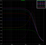
Y-axis is the source impedance as seen by the control grid of a typical guitar amp input stage when using a medium-output humbucker guitar connected with around 10-15ft of cable (450pF cable capacitance). Each line is with a different guitar volume setting as indicated by the legend (apologies to colorblind individuals).
You may (or may not) be surprised how many (very well paid) EEs (with advanced degrees) have trouble with basic electronics. Many go into management - which means they tell other people (who may actually know electronics) what to do. Products often get designed by committees of such people.Incidentally, I'm not an EE, but have successfully imitated one, long enough to hold down a job as electronic design engineer until the company folded in the Dot Com collapse a couple of decades ago.
While there were things I didn't know that most EEs do know, there were also lots of things I knew that most EEs do not.
My employer decided this weighed in my favour sufficiently to offer me the job - particularly when it came to R&D, where knowing "other stuff" came in very handy!
-Gnobuddy
This could result in ignoring simple concepts that sound men know by experience - like gain structure. Get it wrong and you’re going to be clipping in places where you shouldn’t - lazily-designed “just throw chips at it” SS guitar amps no exception.
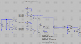
Make C2 very small and see what happens. 0.02 or 0.002uF.Here's a triode emulator I've been working on using opamps, BJTs, and diodes. Seems to work pretty well, but will obviously require scaling the input if you want to overdrive it a lot. It clips correctly into different loads and the harmonic distortion spectrum is pretty darn similar to the tube model over a wide range of input levels. The 12AX7 model is from Adrian Immler.
The time domain plots show the clipping behavior with 1Meg, 100k, and 10k loads. The frequency domain plots show the harmonic spectrum with different input voltages (peak-to-center into the tube, 1Meg load): 300mV, 1V, 3V, and 30V.
I bought my AS73 some twenty years ago, in 2002 or 2003. At that time it was the only affordable semi-hollow electric guitar, shall we say, "inspired" by Gibson's ES-335. IIRC I paid $300 or $350 for it at a Los Angeles area Guitar Center. The equivalent Gibson probably sold for six to ten times the price - I never paid close attention, because I think their prices are entirely absurd.How are the Ibanez guitars? They look like Gibson clones.
I liked the AS73 a lot, especially compared to other e-guitars I owned at the time - a Squier 'Strat and an Epiphone LP 100 (cheap guitar with Les Paul vibes, but with a flat body and screwed-on neck rather than a carved body and glued-in neck.) The Ibanez was well made, looked good, and had some very thoughtful engineering touches (like the slotted "stop-bar" tailpiece that made string changes much quicker).
There were two or three relatively minor things I didn't like quite as much about the guitar. One is that I have big hands and big fingers, and the neck of the AS73 is narrow enough to be cramped for me. Another is that the AS73 has frets made from skinny fret-wire like most Fender guitars - I prefer wider frets of the sort used in most Gibson guitars (aka medium jumbo fret wire).
The third issue is that the fret ends were rather sharp from day one - probably not entirely surprising for a guitar that was manufactured in China, spent three weeks at sea, and then ended up in dry Los Angeles. I finally bought a fret file, watched some You Tube videos, and fixed that just recently.
Some guitarists use them, too. The late Gary Moore was one of them - his playing was very melodic, very creative, and included a wide range of note lengths, from "too fast to hear individual notes" all the way to long notes sustained for several seconds.I'm not surprised at notes ringing for several seconds, with decay. naturally.
Several guitarists including Jeff Beck, Jimi Hendrix, Gary Moore, and Eric Johnson perfected the art of getting their guitars close enough to their very loud amplifiers to create positive feedback, which they learned to control, so that they could basically sustain one note for as long as they wanted. Johnson seemed to use this technique mostly to create beautiful violin-like swells at the start of each note, while Hendrix and Moore both seemed to use it mostly to provide endlessly sustained notes.
Thank you!My description of your skills in the workplace would have maybe been "generalist" and "clever".
I often ended up with projects that weren't really EE material, like the time I developed a subwoofer with motional feedback. The basic idea is to put an accelerometer on the woofer voice-coil, run the output of that through appropriate loop-shaping electronics, and feed it back to the input of the power amplifier.
Done right, you now have active servo feedback over the frequency range of that driver, sensing and correcting the actual motion of the loudspeaker cone so that it follows the audio signal accurately.
This gives you all the usual benefits of negative feedback: the frequency response is flattened, THD is lowered, transient response is speeded up, performance specs are robust against small manufacturing variations, etc. There are also other speaker-specific gains to be had - for instance, a loudspeakers frequency response is normally dictated a great deal by the size and type of enclosure the speaker is mounted in, but with motional feedback, the frequency response remains ruler flat almost regardless of box volume, within reasonable limits.
There were plenty of EEs in the company, none of whom knew anything about physics, acoustics or loudspeakers. They could lay out PCBs and slap together a suitable power amplifier faster than I could, though. (I wasn't familiar with PADS, the PCB layout software they used.)
There were also a couple of excellent loudspeaker designers, who knew lots about loudspeaker drivers and how to design, build, test and measure them, and a little about acoustics. But they knew nothing about designing audio electronics, or servo systems, or how to connect loudspeaker cone motion to actual acoustic sound pressure.
I knew enough of all those areas (and rapidly learned what I didn't know) to be able to pull off the project. I designed and manufactured the accelerometer myself, using the lathe in our machine shop, scrap Perspex, and an ordinary piezo buzzer disc. I measured the complex-number transfer function (Bode plot) from voice-coil voltage to accelerometer output, figured out how to import that into Matlab, and wrote code to design and simulate the servo electronics to keep the thing stable when loop feedback was applied. Then I built, tested, and measured the actual prototype servo electronics.
The speaker guys came up with the actual woofer, I borrowed a suitable loudspeaker enclosure from another prototype, and I used a power amplifier that was already part of the company's line-up.
Keeping the thing stable was a big part of the deal. It's not just a matter of giving yourself adequate gain and phase margin for loop stability; if you drive a speaker hard enough, the voice coil will start to move out of the magnetic field, so the open loop "gain" of the servo will drop; I needed to design a servo that would remain stable even if this happened, i.e. conditional stability was not an option. It had to remain unconditionally stable even if the open-loop gain dropped due to a big transient.
The end result was very satisfying - 18 dB of feedback at the centre of the woofers frequency band, an almost 18-db reduction in 3rd harmonic distortion at low frequencies, complete stability, and a ruler-flat frequency response down to 10 Hz (!) using close micing (microphone within an inch of the speaker cone).
The the company was already swimming in red ink about that time, everyone got laid off in two or three successive waves, and that MFB woofer never saw production. C'est la vie.
Wow. So much for quality control or pride in the products you sell. 🙄VTL5C3...pinned @100Mohms..The casing and potting used is translucent.
Interestingly enough, I quickly realized I couldn't really design my circuit without knowing more about the behaviour of the optocoupler, so I spent a few hours measuring LED current and LDR resistance from 2uA to 10mA....the knee of that LED=>CdS response...
It took a long time because the LDR took quite a while to settle at the low-current end of the curve. Tens of seconds, even.
Then I plotted the data on a log-log graph and looked at it. To a first crude approximation, it's not too far from a straight line when plotted on a log-log graph.
That gave me an idea for a pretty simple equation to fit the data - the resistance looked to be nearly inversely proportional to the LED current!
That idea didn't work out quite right, but it wasn't terribly far off either. Tweaking it a little resulted in a surprisingly simple equation that matches the measured current/resistance data absurdly well over the entire current range (2 uA to 10 mA).
The equation only matches the steady-state resistance, after the LDR has had all the time it needs to settle. So it's not a full mathematical model - it doesn't include the time dependency of the LDR resistance.
Still, the equation was simple enough to let me very easily create an LTSpice model for the optocoupler, and that let me get on with designing the rest of the circuit. Mostly, I needed to know what range of LED currents the circuit would need to produce, and what range of resistance I could expect as a result.
All that data is on my PC at work, so I can't post the optocoupler fit equation or LTSpice model now. I'll try and remember to post it next week. I'm not feeling too well, and won't be going to work today, which is why I'm up at 4 AM. So it'll have to wait until I'm back at work next week.
Again, quite coincidentally, little incandescent bulbs have been on my mind lately. 🙂...grain-of-rice bulbs...
I'm in the midst of building a tiny little PA for my wife and I to use at our weekly music jams. I don't want enormous SPL levels, and detest the poor sound quality from affordable horn tweeters typically used in PA systems.
That made me wonder if I could get away with a dome tweeter designed for Hi-Fi (or rather, "adequate-Fi"). A lot of them will do 90 dB at 1 watt, and can handle maybe 10 watts without burning, so in principle one of them can produce 100 dB SPL (at 1 metre), which is more than I want.
Trouble is, dome tweeters are fragile and easily "blown" in live music usage - unless there's some clever way to protect them?
It turns out that putting a small incandescent light bulb in series with a loudspeaker does a very good job of protecting it. If the bulb is chosen properly, its filament will start to heat up as power levels rise to dangerous levels, that will raise its filament resistance dramatically, and that in turn will limit the power to the speaker, keeping it from burning out. Basically, the bulb acts as a PTC thermistor with the right thermal mass and time constant to protect the speaker, without interfering too much with it during normal short-duration signal peaks or at normal power levels.
The catch is that small incandescent light bulbs are already almost entirely extinct, almost completely replaced by LED "equivalents". Those are certainly equivalent for lighting purposes, but utterly useless as a magic PTC thermistor for protecting tweeters...
I've scrounged up a few old flashlight bulbs, but I think what I really need is something like a 14 volt, 1A bulb, and it hasn't been too easy to find those (I want some spares!) Something like an automotive tail-light bulb might be about right, but they all seem to have been replaced with LED equivalents now.
Even if I find some bulbs that seem about right, I'm not sure there's a safe way to test how effective the protection is. I don't really want to burn out one or more tweeters in the process of trying to find the right bulb!
-Gnobuddy
- Home
- Live Sound
- Instruments and Amps
- Building a SS guitar amp