It depends on your definition, I meant solid state power amp output stages that emulate tube output. In most cases the output stage is a chipamp or a conventional class ab stage, and the emulation takes place upstream. The Peavey Transtube mentioned above seems to me an exception. I found the schematic of the transtube 'Bandit', very interesting!
If anyone knows about other examples, please inform me.
If anyone knows about other examples, please inform me.
For a lower power output the Peavey (Transtube) Backstage 2 (about 10 Watts). I think they used op amps/clipping diodes on the input preamp stages, but the power amp stage used MJE800 / MJE700 complementary Darlingtons. Those are obsolete, but BD680/BD679 would probably be a good substitute. Paired up with a good 10 or 12 inch speaker and multistage JFET preamp instead of the opamp-diodes clipper could be interesting.
"For LF only steady state has any meaning"
It seems I don't understand what that sentence means.
Is there some context or background information you could provide, to help make sense of that?
-Gnobuddy
It seems I don't understand what that sentence means.
Is there some context or background information you could provide, to help make sense of that?
-Gnobuddy
Your welcome and cheers! I'm going to dig through some stuff in the workshop, and see about continuing tests with the jfet multistage with squishy limiter.Thanks!
I know of a couple. The same Russian engineer, KMG, who came up with the best solid-state mimic of a 12AX7 half-triode, also showed on his website a (guitar) power amplifier using FETs and an output transformer. There were some sound clips on his website showcasing the combination of his FET preamp and FET power amp.It seems like nearly all attempts to emulate vacuum tubes with solid state devices focuses on triode preamp stages. Does anyone know of an attempt to emulate tube power amps?
I liked the sound clips, but I don't know how much of the sound came from KMGs preamp, and how much from the power amp.
Several years ago, another diyAudio member mentioned that he was using a similar approach. Power MOSFETs, and an output transformer. He even offered to send me parts to build one of his designs, but at the time, I was drowning in work, and didn't want to disappoint him by taking months to finish the build. So I didn't take him up on his very kind offer.
I don't remember what type of power MOSFETS was being used in either case. The diyAudio thread was from 2015 or 2016, the FETs used may have pre-dated that by many years. Newer power MOSFETs are designed to be used as switching devices, either fully on or fully off, and the nonlinear range in between those is shrinking. For our present purposes, that's not good.
Physicist and audio engineer John Murphy condensed this down to what he called "Duty cycle modulation". Here is a 1994 EE Times interview with Murphy, where he discusses this a bit: https://www.trueaudio.com/at_eetjlm.htmI've found that the dynamic operating point shift (bias excursion) caused by grid conduction and screen grid voltage sag has a big impact on the sound and 'feel'.
Murphy came up with a way to obtain duty cycle modulation from an overdriven op-amp stage (using a diode to shift the operating point in a signal-dependent way). His designs were used in some Carvin solid state guitar amplifiers.
I found sound clips for those early Carvin amps online. To my ears, when heavily overdriven, the sound was quite good, though not as "rich" as a good tube amp. But clean tones were entirely lacking - you just got the the usual thin, cold, sterile, "too clean" tone typical of high-negative-feedback, op-amp based, solid state amps.
It would be interesting to combine a few JFET Fetzer-valve stages (to mimic triodes for good clean tone) with a few of Murphy's bias-shifting op-amp overdrive stages (for good overdrive tone). I wonder if this would combine the good qualities of both approaches, and give you a solid-state preamp that moved progressively from good clean tones all the way to good heavily overdriven tones.
That sounds really interesting. I look forward to seeing any part of your ideas that you would like to share. 🙂In my design, the power tubes are modeled using nonlinear unidirectional current sources coupled to a (scaled) loudspeaker-like load plus some additional components that emulate the output transfomer magnetizing inductance and HF characteristics.
-Gnobuddy
That's the best article I've read in a long time. Thank you!Here is a 1994 EE Times interview with Murphy, where he discusses this a bit: https://www.trueaudio.com/at_eetjlm.htm
With soft limiting diode in local NFB of the JFET there is some bias shifting going on at larger transient input signals. Even without that diode NFB, the gate bias does shift a bit on large input signals (with a self biased common source stage).It would be interesting to combine a few JFET Fetzer-valve stages (to mimic triodes for good clean tone) with a few of Murphy's bias-shifting op-amp overdrive stages (for good overdrive tone).
Nothing new about this, it's at the heart of all DSP. The mathematics has been well understood since Claude Shannon worked it out circa late 1940s.Try drawing a sine wave on a piece of graph paper, then sample it by drawing dots spaced out so that 5 cycles only get 13 dots. Then try to recover the original wave by using only the dots.
Shannon was an intellectual giant even among other giants. He invented all the digital logic gates (AND, OR, NOT) used in digital electronics. He also invented much of what we know on cryptography, and then the entire field of information theory.
It is a very safe bet that mere mortals like you and I are not going to find holes in Shannon's work; he was so much smarter than ordinary people that he might as well have belonged to a different species.
Of course plenty of other brilliant people came along after Shannon, and expanded on the work he had done.
It actually takes only two dots in one cycle to recover the waveform perfectly. No need for 13 dots.
This is THE misunderstanding that's spread all over the Internet. There is no simple non-mathematical, hand-waving explanation that can prove this to be the case - but it's all there in the original research papers in digital audio, and in dozens of textbooks on digital signal processing.
As an analogy: how many dots do you need to represent a straight line exactly? Fifty? A hundred? A thousand?
The correct answer is two (2). A straight line is exactly represented by the mathematical equation y = Ax+B, where A and B are constants. You need only two points - two (x,y) pairs - to find the two constants A and B exactly. Once you know those two, you can perfectly reproduce the straight line.
It's the same general idea with a sinewave. Consider y = A sin(w t), where A and w are constants. Again, you need only two points to solve exactly for A and w, giving you a perfect, zero-error representation of the sine wave. But this time, both points need to occur within one cycle of the sinewave in order to uniquely determine "A" and "w". That's where the Nyquist criterion comes from - the sampling rate has to be high enough to provide at least two points within one cycle of the highest input frequency.
Of course "perfect" and "zero error" don't happen in real life. But "accurate to better than the human ear can detect" only takes 16 bits and a 44.1kHz sampling rate. Proven not only with math, but with lab measurements.
Actually, that is the misunderstanding, in a nutshell...there really isn't a problem. People far smarter than you or I figured it all out, worked out the mathematics, built the technology, and made it happen. The extraordinary genius at the start of all this was Claude Shannon. He single-handedly invented the entirely new field that we now call digital signal processing. And his work has been further developed by a stream of extremely smart people since then.That is the problem in a nutshell.
"Slightest" is woo-woo, not quantitive, and therefore meaningless. But the possible side effects of timing errors are a valid concern, so let's look at that a little more closely, to find out if it really is a problem or not.The slightest imperfection in the timing of the dots
So the hypothesis is: Timing errors from typical off-the-shelf crystal oscillators cause significant errors in the reproduced waveform.
Let's see if we can prove or disprove our hypothesis.
It is trivially easy to get a crystal oscillator with a stability of 100 ppm, or one part in ten thousand. That's long term stability, over days. Short-term stability is considerably better.
As you say, at 44.1 kHz, samples come along every 22.68 microseconds. Let's take the worst possible situation, and assume the oscillator frequency jumps a full 100 ppm in between two successive samples. The timing error is therefore (100 ppm x 22.68), or 2.268 nano seconds.
Let the signal be y = sin (wt) ---> call this equation (1)
Where w is the usual angular frequency, i.e. 2 x pi x f; "y" is the signal amplitude; and "t" is time.
Differentiating equation (1) wrt time, we have: dy = cos (wt) x w x dt
"dy" is the error in the amplitude y. We need to find out how big this error is. "dt" is the timing jitter (error in timing) that resulted in the error dy.
Let's consider the worst-case situation. dy is biggest when cos(wt) is biggest, and the largest value of a cosine waveform is 1, so let's set that to 1.
dy is proportional to w, so the error is worst at the highest frequency. Let's consider 20 kHz, so that w = 2 x pi x 20,000, which calculates to w = 125663.7061.
"dt" is our timing jitter. We already calculated that, worst case, this is 2.268 nanoseconds, or 2.268 x 10^(-9) seconds.
Now we have all the pieces on the right hand side of equation (1). All we have to do is multiply them together.
And when we do, we find that:
dy (worst case) = 0.000284952
Express that as a percentage, and the worst possible error in amplitude due to timing jitter from a typical crystal oscillator is about 0.03%.
An amplitude error of 0.03% is not going to cause harmonic distortion more than 0.03%. (Pretty sure its actually about half that, but I want to keep the math as simple as possible.)
Now we can see why the brilliant engineers at Sony and Philips were not worried about timing jitter. They knew that, using an off-the-shelf crystal oscillator, absolute worst case, timing jitter would never introduce more than 0.03% harmonic distortion.
Which is far below the human audibility threshold.
So we have disproved our original hypothesis. It turns out that timing jitter, using an everyday crystal oscillator, does not cause any audible distortion, even in the worst possible case.
Not "completely", but only by 0.03%, worst case....the wave-form completely changes shape, introducing amplitude modulation.
It's words like "completely" that make some of these claims so hard to take seriously. "Very slightly" is much closer to the truth.
Hypothesis: lots of new frequencies are produced....it's amplitude modulated, so lots of other frequencies are introduced.
Evaluation: If new frequencies are introduced, they would show up in THD measurements. Yet, the original CD standard produced measured THD far lower than any previous-technology audio recording/reproduction chain.
Ergo, lots of new frequencies are not produced at sufficient amplitude to be of any concern whatsoever. If they are created, their amplitudes are very low, and the new frequencies are buried in the noise 90 - 100 dB down. Inaudible.
Incidentally, tape wow and flutter do produce new frequencies - in quite audible quantities. On the original vinyl release of Pink Floyd's "Time", you could hear awful wavering (frequency fluctuations) of the ringing clocks that start the track. That came from tape wow and flutter from the tape recorders used to record and play back the alarm clocks.
I remember making a cassette recording of a pure sine wave from a home-made Wien Bridge oscillator, and listening to the playback. The pitch warbled and fluctuated to a shocking degree - this was no subtle effect, but a very obvious one.
Vinyl suffers from wow and flutter too, mostly wow. You can often hear dramatic wow near the end of a record, when the groove diameter is smallest, and imperfections in the position of the central hole cause dramatic pitch variations.
With CD audio? No audible wow. No audible flutter. No rumble. No print-through. No hiss. No ticks. No pops. No audible noise, it's 90+ dB down. No audible THD.
-Gnobuddy

You're most welcome. 🙂That's the best article I've read in a long time. Thank you!
I think Mr. Murphy deserves a lot more credit and recognition than he ever got.
-Gnobuddy
I used to respond to this better under the older forum search system. IIRC there is an element of our hearing integrating multiple cycles at low frequencies, and many different things have been made of that. Also rooms are to be treated as steady state which is one thing which is probably not relevant to your topic, so keep that in mind if you search the quoted member. There is much information there. (P.S. you can click the arrow in a quote to go to the original post.)Is there some context or background information you could provide, to help make sense of that?
Last edited:
I've noticed this, too. All that square-law nonlinearity leads to partial rectification, and therefore, to signal-dependent bias shift.Even without that diode NFB, the gate bias does shift a bit on large input signals (with a self biased common source stage).
We can hear that bias-shifting and duty cycle modulation in action in the Wampler Plexi-Drive circuit discussed earlier.
Op-amps with symmetrical clipping diodes don't do this at all.
One interesting circuit, which combines a Fetzer-valve FET triode emulation with tone-shaping EQ and asymmetrical diode clipping, is the (no longer manufactured) Cause & Effect Pedals "FET Dream":
Now that he is no longer selling the pedal, the creator of the circuit very kindly uploaded the schematic and other details to Github: https://github.com/Cause-Effect-Pedals/FET-Dream
-Gnobuddy
Sounds pretty good as far as one can tell but still kinda solid state.Now that he is no longer selling the pedal, the creator of the circuit very kindly uploaded the schematic and other details to Github: https://github.com/Cause-Effect-Pedals/FET-Dream
Reminds a little of the tiny marshall rehearsal amps.
Just looked at the Hughes&Kettner "tubeman" schematics but that´s probably a bit too complicate to clone.
Got one and its real nice.
I´d go tube if it was me. And follow that preamp with a Pass-style mosfet follower for a little 1W for home use.
And yes, the Marshall pedals are pretty good sounding.
Here´s two pages with a couple of fun projects:
https://diy-fever.com/amps/12k5_flea_power_amp/
https://web.archive.org/web/2008070...ption=com_content&task=section&id=5&Itemid=36
Pretty much my opinion also. Very nice for a solid-state "dirt pedal", but not really comparable to a good tube amp.Sounds pretty good as far as one can tell but still kinda solid state.
As usual with solid-state, there is very little clean headroom.
-Gnobuddy
Just for the sake of clarity, I should say that my design outputs a line-level signal, not a speaker-level signal, and has an internal load that closely resembles a guitar speaker. It'd be extremely inefficient as an actual power amp. The line output can then be fed into a standard voltage-source power amp to drive a speaker or connected to an audio interface for direct recording. The internal load is adjustable so can be tweaked to match the cabinet in use reasonably well.
Conceptually it's basically an amp plus reactive load in a much smaller, lighter package.
There is one company that has some designs that may work similarly to mine: Origin Effects. They claim that their RevivalDRIVE and related pedals "[...]recreate the entire signal path of a valve amp. This includes not only the preamp, phase inverter, power amp and rectifier stages, but also a synthesised mains power signal and a speaker-emulating reactive load" (from the manual). I'm not aware of any public information about the circuit design though (other than the tiny bit revealed in their marketing material).
I may build the tube version of the circuit I've tried to emulate at some point. It's possible I may be able to find someone that already has the equipment required to do a fair comparison (the amp plus a good reactive load like the Suhr unit).
AIso related to Murphy's article: I chuckle a bit now when I see 'asymmetrical' parallel diode clipping arrangements, having looked at how they perform. Duty cycle modulation is required in order to get significant even-order harmonic content (at least at high drive levels). Asymmetrical parallel diodes don't work well at all if that's the goal.
Conceptually it's basically an amp plus reactive load in a much smaller, lighter package.
Thanks, I have looked at the Transtube circuits a bit, but not the Valvetronix. I had a previous design that was more along the lines of the Quilter amps (including the dynamic crossover distortion circuit), but I wasn't completely satisfied with the sound (it's certainly possible that Pat Quilter did it better than me 😉). To my ears, the way the tubes interact with the speaker load when they clip is important and is not emulated properly in a design that uses a more-or-less standard clipping stage fed into a clean power amp with high output impedance.1 and a half 😉 very good ones :
There is one company that has some designs that may work similarly to mine: Origin Effects. They claim that their RevivalDRIVE and related pedals "[...]recreate the entire signal path of a valve amp. This includes not only the preamp, phase inverter, power amp and rectifier stages, but also a synthesised mains power signal and a speaker-emulating reactive load" (from the manual). I'm not aware of any public information about the circuit design though (other than the tiny bit revealed in their marketing material).
I may build the tube version of the circuit I've tried to emulate at some point. It's possible I may be able to find someone that already has the equipment required to do a fair comparison (the amp plus a good reactive load like the Suhr unit).
I actually did see that recently, but I haven't really looked at the design very carefully.The same Russian engineer, KMG, who came up with the best solid-state mimic of a 12AX7 half-triode, also showed on his website a (guitar) power amplifier using FETs and an output transformer.
This describes what happens with single-ended stages, but a push-pull power section is a bit different, as you might imagine. Most of the dynamic operating point shift in the power tubes of a typical so-called "fixed bias" guitar amp comes from the sagging screen grid supply, though the grid conduction contributes as well. As the operating point shifts colder, the overall gain is reduced, so you get a subtle compression effect. Crossover distortion becomes considerable at some point too, of course.Physicist and audio engineer John Murphy condensed this down to what he called "Duty cycle modulation".
AIso related to Murphy's article: I chuckle a bit now when I see 'asymmetrical' parallel diode clipping arrangements, having looked at how they perform. Duty cycle modulation is required in order to get significant even-order harmonic content (at least at high drive levels). Asymmetrical parallel diodes don't work well at all if that's the goal.
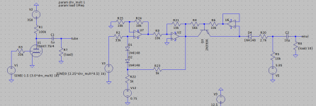
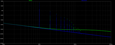
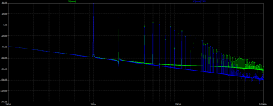
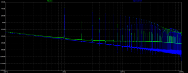
Here's a triode emulator I've been working on using opamps, BJTs, and diodes. Seems to work pretty well, but will obviously require scaling the input if you want to overdrive it a lot. It clips correctly into different loads and the harmonic distortion spectrum is pretty darn similar to the tube model over a wide range of input levels. The 12AX7 model is from Adrian Immler.
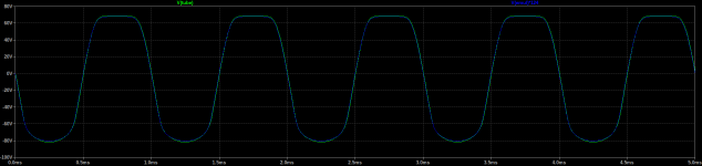
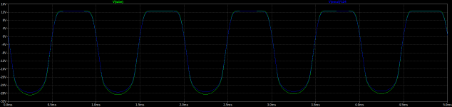
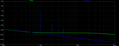
The time domain plots show the clipping behavior with 1Meg, 100k, and 10k loads. The frequency domain plots show the harmonic spectrum with different input voltages (peak-to-center into the tube, 1Meg load): 300mV, 1V, 3V, and 30V.
The time domain plots show the clipping behavior with 1Meg, 100k, and 10k loads. The frequency domain plots show the harmonic spectrum with different input voltages (peak-to-center into the tube, 1Meg load): 300mV, 1V, 3V, and 30V.
Attachments

Last edited:
The Flammia preamp is the one to clone for sure. That does sound superb.Very nice for a solid-state "dirt pedal", but not really comparable to a good tube amp.
I´d probably (naively) start with a jfet buffer at the input (2 jfets + 2 resistors as in the Nelson Pass crossover),
follow that with a Fetzer valve circuit. Distortion + EQ stage which would be kinda the big question for me on how to realize.
Eventually another buffer plus a single ended output stage with FETs or so.
(Nelson Pass simple follower, lineup´s 4W Class-A, SEWA amplifier, Passlabs clone etc.)
I made a layout for the follower and a preamp already which could be a nice fit (at least for <1W output):
simple follower with preamp
Should be fun to make a little preamp PCB that accounts for a couple of options and then breadboard "the sound forming part" until its right.
It will be lots of work though = lots of trying. (taking the best parts of designs that are found online, like the Marshall pedals could be a quicker solution or asking in those more specific forums; haven´t done lots of research)
That looks very impressive! I tried to understand how the schematic works, but I got lost after the first opamp... Could you explain it a bit?Here's a triode emulator I've been working on using opamps, BJTs, and diodes.
The input diodes emulate the grid conduction/rectification. The first opamp provides a bit of gain and the second is just an inverting buffer. Q3, R6, R4, and U6 form a buffered rubber diode, which basically just acts like a long string of diodes in this case. R20 makes the emulated anode resistance more accurate. The rubber diode and D4 are forward biased through R5 by V5. When D4 becomes reverse biased, it's like the tube going into cutoff. R5 is analogous to the anode load resistor (scaled down 10x from the tube circuit).
Thanks, it's starting to dawn. And why are the input diodes and R22 + R23 connected the way they are?The input diodes emulate the grid conduction/rectification. The first opamp provides a bit of gain and the second is just an inverting buffer. Q3, R6, R4, and U6 form a buffered rubber diode, which basically just acts like a long string of diodes in this case. R20 makes the emulated anode resistance more accurate. The rubber diode and D4 are forward biased through R5 by V5. When D4 becomes reverse biased, it's like the tube going into cutoff. R5 is analogous to the anode load resistor (scaled down 10x from the tube circuit).
- Home
- Live Sound
- Instruments and Amps
- Building a SS guitar amp