The negative feedback changes the shape of the transfer curve to better match the tube. It's also required if you want to properly emulate the shelving filter created by your typical cathode-bias arrangement (my example is fixed bias).
To paraphrase yourself, that is woo-woo.It actually takes only two dots in one cycle to recover the waveform perfectly. No need for 13 dots...
½ of the sampling rate is an asymptotal hard limit that cannot be used in practice. A string of zeroes could imply a sine wave of any amplitude at 0⁰, 180⁰, 360⁰ etc. And a string of 1, -1, 1, -1... could just as easily be peaks, or nulls between much larger peaks.
What's possibly worse is that even after aliasing is taken care of, moire-like diffraction patterns are still common and easy to observe. At 11.024 kHz for instance, the phase of each set of 4.xx samples per cycle will gradually change over the course of 1000s of cycles, producing very slow amplutude modulation. I suppose a good enough DAC could recover the correct amplitude, but at the cost of huge buffers and additional processing. And that's assuming perfect clocking with no drift on the mastering side as well.
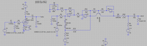
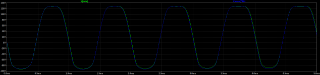
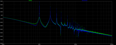
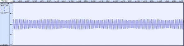
Here's an AC coupled cathode bias triode emulation. I didn't try as hard to get it perfect this time, but it's still pretty close. This one is set up with more gain. Duty cycle modulation is clearly visible switching between the first and second time domain views (0-5ms and 95-100ms). Harmonic spectrum is pretty darn close again. 2nd harmonic amplitude error is less than 1dB.
Attachments

And because of that, in practice there are steep low-pass filters before any A/D converter, to exclude frequencies at exactly 1/2 of the sampling rate. In practice such problem you are describing (hoping for?) never occur. Only two dots in one cycle very close to the 1/2 sampling frequency is enough, indeed.½ of the sampling rate is an asymptotal hard limit that cannot be used in practice. A string of zeroes could imply a sine wave of any amplitude at 0⁰, 180⁰, 360⁰ etc. And a string of 1, -1, 1, -1... could just as easily be peaks, or nulls between much larger peaks.
Looks really great! Have you also tried putting two stages like that in series? would they react the same way as tube stages?Here's an AC coupled cathode bias triode emulation. I didn't try as hard to get it perfect this time, but it's still pretty close. This one is set up with more gain. Duty cycle modulation is clearly visible switching between the first and second time domain views (0-5ms and 95-100ms). Harmonic spectrum is pretty darn close again. 2nd harmonic amplitude error is less than 1dB.
No, it is not. If you had tried the little exercise I described, you would see for yourself. As it stands, you are b--s-ing. In "practice" you never even tried.And because of that, in practice there are steep low-pass filters before any A/D converter, to exclude frequencies at exactly 1/2 of the sampling rate. In practice such problem you are describing (hoping for?) never occur. Only two dots in one cycle very close to the 1/2 sampling frequency is enough, indeed.
Theoretically, yes. The grid conduction and nonlinear output impedance are modeled pretty accurately, which are two important factors. One other thing that I didn't include is the grid to plate capacitance, but that's easy to add.would they react the same way as tube stages?
I have. It depends on the filter used, not surprisingly. Some reconstruction filters allow some aliasing (tradeoff for better bandwith with lower filter complexity), which will cause something like what you describe. Others reach their full 90+dB attenuation before Fs/2 and therefore do not show the same behavior.In "practice" you never even tried.
Presenting: a "mathematically perfect" sine sweep from 10kHz to 20kHz, sampled at a "perfect" 44.1k. Zoomed in on ~11kHz to verify that it's not just the screen resolution creating moire patterns. Aliasing is its own separate thing.
Attachments
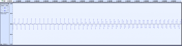
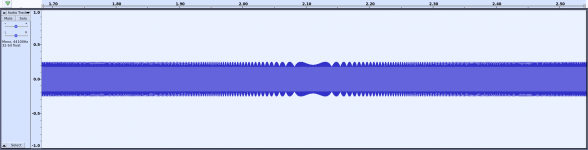
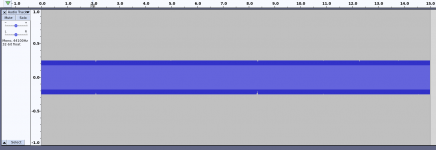
If you looked closely, you'd realize that audacity simply connects the dots for its waveform display (linear interpolation). This is not what happens in a DAC. With a real reconstruction filter this moiré-like effect goes away.
And how many samples do they use for buffering? An infinite number as per the theorem, which applies to pure theoretical sine waves with no beginning or end?
Sorry, but is this a joke?
Yes, perfect reconstruction requires an infinitely long filter, which means infinite latency. But mathematically perfect reconstruction is not required for the output to be audibly perfect.
In any case, I don't see what sampling theory has to do with solid state guitar amps...
Yes, perfect reconstruction requires an infinitely long filter, which means infinite latency. But mathematically perfect reconstruction is not required for the output to be audibly perfect.
In any case, I don't see what sampling theory has to do with solid state guitar amps...
"Pure theoretical sine waves with no beginning or end" do not exist in the reality of audio recordings,. All audio recording known to men are of finite length! You should know that. 🙄And how many samples do they use for buffering? An infinite number as per the theorem, which applies to pure theoretical sine waves with no beginning or end?
In any case, I don't see what sampling theory has to do with solid state guitar amps...
Yes, you are right -- I just hate to leave wrong opinions stated as 'fact' unchallenged. Don't mind me...
For me, I would start with the output stage, making everything as 'musical' as possible. My ideas about what that means probably differ from other people:
If ultra-low distortion and a cleaned-up sound is not necessary, then negative feedback should be avoided, except for special effects.
The input stage could have adjustable input resistance to vary loading on the strings. One thing I've noticed is that the pick-up coil physically loads the strings, changing the sound and adding a slow or fast 'twang'. Magnets also do this, but the point is that the coil absorbs a bit of energy from the strings. A lot of untapped potential there.
It is remarkable I think that there are audiophile solid state amplifiers that use little or no global negative feedback, to get a 'nice' sound, while ss guitar amps without feedback are very rare. The often used mixed mode feedback, is to raise the output impedance, wich is low because of the negative feedback used in the first place. It would be much more logical to design a low gain power amp without feedback, wich is how iconic tube amps like the Vox and Fender tweed Deluxe work.If ultra-low distortion and a cleaned-up sound is not necessary, then negative feedback should be avoided, except for special effects.
You didn't challenge anything, you just managed to show publicly how much you don't know about the established facts from reality/practice and theory.I just hate to leave wrong opinions stated as 'fact' unchallenged.
It is remarkable I think that there are audiophile solid state amplifiers that use little or no global negative feedback, to get a 'nice' sound, while ss guitar amps without feedback are very rare. The often used mixed mode feedback, is to raise the output impedance, wich is low because of the negative feedback used in the first place. It would be much more logical to design a low gain power amp without feedback, wich is how iconic tube amps like the Vox and Fender tweed Deluxe work.
Even my headphone amplifier sounds great, despite (or perhaps because of) a lack of feedback except for source degeneration, and a terribly flawed/flaky JFET input stage.
I'm not traditionally a "guitar guy", but I actually built one myself, except that the piezo pick-up is a bit lacking. One of my many to-do's is a new pick-up, possibly a low profile PCB based one to avoid having to cut a big notch in the neck. The tone from a 2-4kHz resonance would be missing, unless I somehow factor it in.
"woo-woo" is blind belief with neither mathematics not experimental evidence to support it. That's what you've been offering.To paraphrase yourself, that is woo-woo.
Excellent. At least you no longer think you need 13 points per 5 cycles. That's progress.½ of the sampling rate is an asymptotal hard limit that cannot be used in practice.
In post #149, I wrote "...you need only two points to solve exactly for A and w, giving you a perfect, zero-error representation of the sine wave. But this time, both points need to occur within one cycle of the sinewave"
In order to have two points within one cycle, the sampling frequency has to be slightly higher than twice the signal frequency. Otherwise the two points wouldn't occur WITHIN one cycle.
So, in this case, what I wrote was entirely correct. More importantly, what I wrote was merely a simplified summary of work that's been published in thousands of peer-reviewed research papers. That work has standing and merits far beyond anything I write.
If the string of zeros is infinitely long, yes. Even in an imaginary noise-free world, that has zero probability, just like rolling an infinite number of sixes with a dice. A non-issue.A string of zeroes could imply a sine wave of any amplitude at 0⁰, 180⁰, 360⁰ etc.
In reality, there is also an unavoidable noise floor under any signal. With a high-resolution A/D converter, that tiny noise background is sufficient to bump the smallest bits in the A/D conversion around. The A/D converter never outputs a stream of zeros - it outputs a stream of very small-value numbers that vary with the instantaneous noise voltage.
Incorrect. 1,-1, 1,-1 could only occur right at the Nyquist frequency, since there are only two points per cycle. As you yourself pointed out, this is a frequency too high to be represented at this sampling rate.And a string of 1, -1, 1, -1... could just as easily be peaks, or nulls between much larger peaks.
Since frequencies at and above the Nyquist frequency have been eliminated from the input by the anti-aliasing signal, and eliminated from the output by the reconstruction filter, zero output is produced at this frequency. Your hypothetical case of (1,-1), (1,-1) samples isn't even within the allowed signal domain (it could only occur at 22.05 kHz with a 44.1 kHz sampling frequency). Your concern is therefore a non-issue.
If the frequency is even fractionally lower (as required for a digital representation to work), there will, by definition, be other data points in between the (-1) and the (+1) points. And those will uniquely determine the frequency and amplitude of the signal, which will be correctly reproduced. Once again, your concern is a non-issue.
You are not going to find holes in DSP. People far smarter than you or I worked all this out, and it has been refined and tested literally billions of times over the last 70 years or so, ever since Claude Shannon's original ground-breaking work was completed. Digital signal processing is everywhere these days, from cellphones to satellites.
As Sonce already explained, you are looking at artifacts of the PLOTTING process, which have absolutely nothing to do with DSP.What's possibly worse is that even after aliasing is taken care of, moire-like diffraction patterns are still common and easy to observe.
If the signal is [A sin(w t)], the individual points at times (t1, t2, t3,.....) represent the corresponding signal amplitudes A sin(w t1), A sin(w t2), A sin(w t3), and so on.
There is no requirement at all that (w t1), (w t2), and (w t3) have to be synchronized with the waveform itself; there's no problem at all if the phase at the sampled points varies from one cycle to the other, producing moire patterns when you plot the data. I can't imagine why you think there is a problem here.

In the appearance of the graph, seen by the eye. But that has nothing to do with the signal emerging from the reconstruction filter, as Sonce already pointed out.At 11.024 kHz for instance, the phase of each set of 4.xx samples per cycle will gradually change over the course of 1000s of cycles, producing very slow amplutude modulation.
None of this is true.I suppose a good enough DAC could recover the correct amplitude, but at the cost of huge buffers and additional processing. And that's assuming perfect clocking with no drift on the mastering side as well.
1) Any correctly operating DAC will do it.
2) A buffer is not mathematically necessary at all - they are only used to allow for the fact that there is a varying latency in the response of a microprocessor (it can't read data if its busy doing something else, it can't clock data out if it's busy doing something else). So engineers add buffers to store enough information to allow for the microprocessor to come along and fetch it when it (the microprocessor) "has its hands free".
In short, buffers exist for the same reason factories have warehouses; having a little stock on-hand helps you absorb glitches in the delivery of supplies and the removal of finished products.
The specialized microprocessor we call digital signal processors tend to have very slight delays like this, and very small buffers are sufficient.
On the other hand, the microprocessors (and ancillary hardware) in our computers are very busy multi-tasking, doing all sorts of different tasks. Depending on the operating system, and the electrical interface to it, there may be considerable delays in signal processing. If the operating system is very poor at its job, and a slow interface like USB is used, then large data storage buffers may be necessary - for the same reason why factories need larger warehouses if transportation is very erratic and unreliable in that city.
3) I have already disposed of your "it needs perfect clocking" hypothesis. Using a simple back-of-the-envelope calculation, I showed you that a cheap crystal oscillator provides such accurate clocking, that distortions are suppressed below 0.03%.
So here is the situation. We have reached an impasse; it's clear that I cannot help you to understand DSP. And you are certainly not going to convert me to your belief that DSP somehow doesn't work, though there are literally billions of devices on earth proving the opposite at this very moment (it is in every cellphone, for example.)
To get any actual traction with your beliefs, you're going to have to prove them, to the same rigorous standards as the existing enormous body of mathematical and engineering data. I suggest you work up the rigorous mathematics needed to disprove the last seventy years work on digital signal processing, collect unassailable experimental evidence showing that all the billions of DSP circuits and devices in the world actually don't work, write up your own research paper containing your math and data, have the paper successfully peer-reviewed, and let us know when it's published in a top-notch peer-reviewed research journal. It would be an epic scientific breakthrough, overturning 70 year's theoretical and experimental work, so I have no doubt that it would be published, if you could prove it. And at that point, the the rest of the world would start to take it seriously.
In the meantime, I believe you and I would both waste less of our time, and experience more happiness, if we didn't see each other's posts here on diyAudio. So please put my username on your ignore list, and I will do the same with yours.
We live in hard times, happiness and peace are precious and diminished commodities, and I hope you thrive in the midst of it all. You have my best wishes.
-Gnobuddy

I was sufficiently impressed by Brett Kingman's demo to buy one. I agree, it's a superb product. And when you look at the price as well, it's a total no-brainer.The Flammia preamp is the one to clone for sure. That does sound superb.
If I was nit-picking, I would like a slight extension in treble response. The cab simulator in the Flamma Preamp is a little more aggressive than I would ideally like, for my personal tastes.
I'm pretty sure Flamma actually lets you turn off the built-in cab simulator if you want to. And they also make a separate cab-simulator pedal, with multiple different cab sims to choose from, as well as the ability to import external cab sim impulse responses.
I'm not that picky, so I'm content with the built-in response of the Flamma Preamp. As you say, it sounds superb.
I think many pedals are good at producing lots and lots of distortion, but few of them tackle the "very subtle distortion" end of the spectrum, that you get naturally from a couple of vacuum triodes....the best parts of designs that are found online, like the Marshall pedals...
It's easy to think of reasons for this. For one, it's hard to keep simple solid-state circuits from overloading abruptly, and creating lots of distortion. For another, from the point of commercial manufacture, if your pedal produces very subtle distortion, you will lose an enormous fraction of potential customers. Customers won't fork out the money for a pedal unless they immediately an unequivocally hear a dramatic change in their guitar sound.
Possibly for the same reason, older DSP guitar amp modellers - at least the ones I could afford - also didn't seem to make much of an attempt to emulate clean tones from a good tube amp, such as vintage Blackface Fender guitar amp designs. Instead, they went straight to harsh, agressive distortion.
That began to change a few years ago. The Boss/Roland Katana guitar amps was the first somewhat-affordable DSP guitar amp product I'd heard that did a good job with nice liquid, "tubey" clean tones at some settings. After taxes, the Katana 50 cost about $500 CAD when I bought mine, not exactly cheap.
One of the many things I like about the Flamma Preamp is that it emulates subtle "tubey" clean tones, and it does it quite well. My favourite clean tones from this pedal include the inevitable Fender model ("Deluxe Blue", a simulation of a Fender Blues Deluxe), and also the clean channel of model number 3, which is supposed to represent a Two-Rock Coral. I've never seen or heard a real Coral, but the clean channel of the Flamma emulation sounds very nice.
IMO, chances of a DIY solid state analogue guitar amp outperforming a Flamma Preamp are slim to none. KMG's rather complicated FET preamp + FET poweramp is very good, but is still limited to essentially one good sound, just like a real tube amp.
The Flamma Preamp, on the other hand, has 14 separate very good sounds you can dial up at the push of a couple of buttons. One of the huge advantages of digital over analogue signal processing.
With the surprisingly good sounds and surprisingly low cost of the Flamma Preamp, if I wanted to DIY my own portable guitar amp for "busking", I would chuck a Flamma Preamp, a reverb pedal, a TPA3116D2 or similar power-amp module, and a lithium-ion cordless tool battery into a home-made plywood box, add a suitable speaker or two, and be done with it.
Obligatory safety-related comment: all lithium batteries pose a significant fire hazard, and you should not use one in any DIY product, otherwise you create the possibility of burning your house down with possible injuries or loss of life. And you won't be covered by insurance.
-Gnobuddy
I'm getting curious about this flamma thing. But, good and affordable as it may be, in the end the thing about diy is that creating something yourself is more rewarding than buying stuff.I would chuck a Flamma Preamp, a reverb pedal, a TPA3116D2 or similar power-amp module, and a lithium-ion cordless tool battery into a home-made plywood box, add a suitable speaker or two, and be done with it.
- Home
- Live Sound
- Instruments and Amps
- Building a SS guitar amp