Thanks for testing and reporting!...sounds like a tube screamer, but a bit harsher on high frequencies...
If I understand you correctly, you found the 2BJTE circuit sounds nothing like the sound clip Azevedo posted?
To me, the tube screamer and the millions of similar diode clipper circuits it spawned are about as bad as it gets in terms of unpleasant solid-state distortion.
The original transistor-based Big Muff used exactly the same idea, but sounds less harsh than the Tube Screamer and family, probably because the individual transistor stages in the original Muff don't have as much gain, or clip as hard, as op-amps do.
IIRC diodes in the feedback loop had been used in analogue computers well before the original Big Muff (the output voltage is the logarithm of the input voltage!), so that's probably where Bob Myers got the idea from.
In short, I'm not a fan of the Tube Screamer sound unless used the way Stevie Ray Vaugn did - as a subtle clean boost to make his tube guitar amplifier overdrive a bit more than usual, with little or no distortion from the actual Tube Screamer.
Could you try running the 2BJTE circuit with very small input signals? In simulation, 10-15mV the input is enough to cause significant distortion. You might need to attenuate the raw guitar signal (a lot!) before it goes to the 2BJTE circuit, rather than amplify it.
I'm wondering if the circuit will distort in a more pleasant way if not pushed all the way to flat-topped clipping.
Well, that's encouraging!It is a circuit worth fooling around with I think, you do get a lot of tone for only two transistors...
-Gnobuddy

It's been a number of years since I found and read the original thread, but my recollection is that Azevedo said he started with something he referred to as "Jack Orman's Muffer", built it on a breadboard, and decided to find out if bootstrapping would change its sound.I still don't get why C2 is there exactly.
As best I can tell, the 2BJTE circuit was created by plugging and unplugging various components into the breadboard, listening for changes each time.
I think Azevedo thought that R2 would stabilize the operating point, but it won't, because it's too small. I suspect he thought C2 would act as the usual emitter bypass cap, but had no idea that he picked a value ten thousand times too small to have any effect at guitar frequencies. (C2 only bypasses R2 at frequencies above 1 MHz.)
From the sound clip, I was hoping that serendipity had struck, as it did with the discovery of penicillin. That the 2BJTE circuit, by sheer accident, just happened to produce really good-sounding guitar distortion.
After Gijser's post, I'm now wondering exactly how Azevedo's original clip was created. Is it a case of finding the right signal levels to get the circuit to sound its best? Or was the Boss OD3 actually providing the lovely distortion, though Azevedo didn't realize it? 🙂
I should find out for myself by following Gijser's lead, but it might have to wait a bit before I can find the time, and more importantly, the energy.
-Gnobuddy
I'm wondering if the circuit will distort in a more pleasant way if not pushed all the way to flat-topped clipping.
I used the JFET stage more as a buffer, at low output level. I don't like too much overdrive/distortion, I think a tubescreamer can sound pretty good, but I never use it cranked way up. Not my kind of sound. The 2BJTE circuit I think also sounds best with not so much drive.
An idea I have now is to replace the first transistor with a JFET, its high input impedance would allow a direct guitar input. Tinker time!
Well it may be that at the core of it, the configuration could make for some good low order harmonic distortion that is progressive with guitar signal input level. That is worth looking at.That the 2BJTE circuit, by sheer accident, just happened to produce really good-sounding guitar distortion
Even if we assume the OD3 was indeed set ''clean'', there would be some pre-EQ of the guitar signal through it. That pre-distortion response curve would play a part in the overall sound for sure.Or was the Boss OD3 actually providing the lovely distortion, though Azevedo didn't realize it?
I agree. The C2 emitter bypass establishes a low frequency cutoff of 1 MHz, but normally this emitter bypass cap would boost frequencies above 1 MHz..though R2 is way too small that it really doesn`t bypass anything to DC ground, the emitter is pretty close to DC ground already.I think Azevedo thought that R2 would stabilize the operating point, but it won't, because it's too small. I suspect he thought C2 would act as the usual emitter bypass cap, but had no idea that he picked a value ten thousand times too small to have any effect at guitar frequencies. (C2 only bypasses R2 at frequencies above 1 MHz.)
If I were to explore this circuit, I would remove C2, short R2 and confirm there is no audible difference. Then I would try increasing R2 (use a variable trim pot).
It may be that R2 is optimal at a higher resistance (perhaps 330 instead of 33 Ohm?). I figure by about 1K and up the transistor will start behaving like a normal CE stage, but that remains to be proven out. Maybe I'll have some time to check..
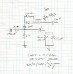
Orman also did a project called FET Muffer. I did manage to find a pic of that schematic (though I won`t post it)..but interestingly the two Jfet (CS) stages that do the clipping, instead of two paralleled/reversed diodes from drain to gate, there is a single diode on each stage. This is similar to what I did on my Jfet boost with soft limiter using a single diode but with series and parallel resistors. What appeals to me about using the series and parallel resistors with the diode NFB is that the diode is not hard switching between its conductive and non conductive states. The diode has a small curve up to the knee from zero volts to full forward conduction, and series resistance ''stretches out that curve'' while the parallel resistance effects the slope of the diode I-V characteristic. The result is no sharp edged clipping, no raspy-ness..I did not need to add caps across the diode to tame any harsh noisy clipping.. there really wasn't anything bad to filter out.Azevedo said he started with something he referred to as "Jack Orman's Muffer"
I also noted that with the single diode basically compressing half the signal cycle, that this would introduce some bias shifting of the Jfet at least for large level signals, until the note decays and the self bias Jfet settles down. I measured this a while back on my Jfet booster and at the source it would shift in the order of about 10 to 20 mV..I'll need to reconfirm as it`s been a while.
I found out that Azevedo actually has a website, with a page about solid state tube emulation featuring the 2BJTE circuit: https://nexp.pt/tube_emulation.html
He apparently was inspired by the work of Tim Escobedo, and even has a 'tribute' page on his site with, among many other circuits, this 'FET driver':

Looks a lot like the idea I mentioned in my previous post... I am going to play with this.
He apparently was inspired by the work of Tim Escobedo, and even has a 'tribute' page on his site with, among many other circuits, this 'FET driver':
Looks a lot like the idea I mentioned in my previous post... I am going to play with this.
I am curious, could you post a schematic?This is similar to what I did on my Jfet boost with soft limiter using a single diode but with series and parallel resistors.
Sure thing.. it`s a work in progress as mentioned. CheersI am curious, could you post a schematic?
Attachments
Hello man, I create an account just to ask you lolThe tricky bit is that the "scaling voltage" in the exponential is only 26 millivolts. In other words, every 26 mV increase in Vbe causes nearly a tripling of collector current!
This follows from the Shockley equation that describes an ideal BJT transfer function. Modern silicon small-signal BJTs accurately follow that equation over several orders of magnitude of collector current.
For our present purposes, this enormous voltage sensitivity can be a problem.
For example, if you have a common-emitter stage with the collector biased to half-Vcc, doubling the collector current will result in saturation (Vce=0), and a flat-bottomed output waveform. From the Shockley equation, it only takes an 18 mV positive peak in the input signal to achieve this!
To place that in context, we know from 'scope captures that a typical guitar can put out 1500 mV positive peaks under reasonable playing conditions (hard strumming). Even gentle playing may put out 100 mV peaks. Yet, our simple common-emitter stage is already hard-clipping at only 18 mV positive peaks!
Interestingly, in the very early days of semiconductor guitar devices, this approach was used more than once. The "Dallas Rangemaster" schematic is one good example ( https://www.electrosmash.com/images/tech/rangemaster/dallas-rangemaster-schematic-parts.png ).
The Rangemaster consists of a single common-emitter germanium transistor amplifier stage, with no negative feedback anywhere. Input impedance from the leaky, low-beta Ge transistor would have been far too low to be acceptable today, and the much-too-small input capacitor stripped out most of the bass frequencies from the guitar, while the much-too-low input impedance stripped out a lot of the high frequencies as well.
Brian May (of Queen) is one famous guitarist who used a Rangemaster. There is a current thread elsewhere on diyAudio where there has been some discussion of May's famous guitar sound, and where it came from.
Those leaky old Ge transistors didn't follow the Shockley equation as closely as the better transistors of today do. They don't saturate as hard as modern Si devices do, either. Those things may have had something to do with the fact that the Rangemaster didn't sound harsh in Brian May's recordings.
Typical JFET curves are spread over a considerably larger voltage spread than BJT curves. This means they tend to have low voltage gains too, as device transconductance is far lower than a BJT.
These are qualities that pushed the FET out of favour for small-signal voltage amplification a long time ago. But for an e-guitar amplifier, these "weaknesses" might actually be assets.
I have never heard an FET-based SS guitar amp that sounded just like a good tube amp - but they also tend not to sound harsh, and IMO it is fairly easy to get some relatively sweet-sounding distortion out of an FET or two.
There is a real conundrum here. Musicians, by nature, tend to be superstitious about their instruments and gear, and so scientists and engineers have to take their input with a grain of sand, or do careful controlled, double-blind experiments so they don't end up believing in musical Loch Ness Monsters.
On the other hand, MRI scans of musican's brains literally show that they have been significantly re-wired to favour auditory inputs over other sensory inputs. Human brains are quite flexible, and years of focusing on music can and does change them. Great musicians certainly hear things the rest of us cannot.
It makes perfect sense that musicians tend to be superstitious and subjective. If the musician doesn't see rainbows and hear angels when she plays her instrument, her audience certainly is not going to see and hear those things.
Me, I have a foot in each camp. My education is solidly in objective science. As an amateur musician (though definitely not a great one), when I play music, I do my best to switch to the "rainbows and angels" subjective, illogical, non-critical, right-brain-dominant, state of mind. It's the only state of mind from which you can create good music.
Concerns over superstitious beliefs aside, the "clean tone is too clean" complaint is no mystery, and we don't have to invoke superstition to explain it. A single half-12AX7 triode in a simple common-cathode amplifier stage can generate 5% low-order THD, and decades of experiments in the Hi-Fi world have shown that a significant number of people can hear as little as 1% THD on a pure sine wave audio tone.
5% THD is greater than 1% THD. If people can hear 1% THD, they can certainly hear 5% THD. Q.E.D - "and thus it is demonstrated"!
An e-guitar signal isn't a pure sine wave, not even close. It contains lots of harmonics, even if you play a single string. This means slight nonlinearities in the amplifier also generate intermodulation distortion (IMD), which is even easier to detect than THD alone.
So there's no doubt that people with a good pair of ears (no magic golden ears necessary) can indeed hear the slight change in guitar clean tone that results from going through, say, four cascaded stages of vacuum tube amplification, each one adding a few percent THD.
Going through four or more tube stages is quite typical of many of Leo Fender's tube guitar amp designs. Newer, higher-gain tube amps may have a lot more stages than that. So we're talking about maybe up to 20% THD in a guitar "clean" tone!
Some years ago, I spent quite a lot of time coming up with a design for a 2-watt tube guitar amp, the hope being to achieve good tone at low enough SPL to be usable in an apartment. Without an oscilloscope at the beginning, I tweaked my circuit by ear until I managed to get a good clean tone. When I bought a 'scope later, I was surprised to see around 20% THD, low order, mostly 2nd harmonic, from my carefully tweaked design. This, remember, was what my ears wanted in order to get an appealing clean guitar tone. At the time, I was very surprised by how much distortion still sounded "clean".
That was a low-power amp at relatively low SPL. Our ears are more sensitive to THD at somewhat higher loudness levels, and it is quite likely that an amp as loud as, say, a Fender Twin, needs much less than 20% THD to audibly colour the clean tones.
No wonder op-amp stages with 0.001% THD sound "too clean"!
-Gnobuddy
What do you think about sunn o?
What ur thought about "doom" type distortion? brutal low end, gnarly, swoosh, brrghhzzz that only good while playing chords lol
Now that's super interesting. I've always wondered if effects boxes respond differently when a pickup is simply passively connected, versus a buffered output (9V battery in the guitar gives the hint it's buffered) and there it is; a circuit with some compensating element that addresses this. His description of how it behaves relative to playing is pretty good too.even has a 'tribute' page on his site with
Just a little update on the soft limiting Jfet booster, I built one for a friend who plays bass. This time I put it into a bigger box and there's a switch to go between cleanish JFET boost only, and 1 or 2 diode drops limiting. I am not using the single diode in one direction, rather one or two pairs of diodes in reverse parallel. The JFET alone has just enough asymmetric distortion to get a warmed up sound that still perceived as "clean". Switching in 2 diode pairs gives a nice amount of grit, which on a solid state Ampeg bass amp sounded good. With a single diode pair, this starts to sound like heavy overdriven bass, almost into a compressed fuzz territory. The 500 K in the NFB was replaced with an adjustable "gain" pot, so when the diode limiting is on, you can vary the amount of grit/distortion.
The booster stage I posted earlier is best to be driven from a buffer, I used a source follower JFET stage. It will work without it, but the input impedance with the inverting NFB circuit drops quite a lot.
Anyways, I am looking at JFET-PNP compound stages now..hoping to get something together with some tone controls. My solid state Traynor Bloc 100 uses those types of stages in the preamp section, and I really like it's "clean" channel.
- Home
- Live Sound
- Instruments and Amps
- Building a SS guitar amp