...and, IMO, most make very bad managers. Good engineers rarely have good people skills....EEs...Many go into management...
My impression is that freshly-minted EEs often only have a shelf life of 2 - 3 years before they have to move into management, or get fired and replaced by younger engineers with more current skills who will work for lower pay.
It's a poor system, and IMO, not the way it should be. Good engineers get better with age, like wine. Those years of experience give them knowledge and skills that young college graduates don't have.
When I was teaching large classes full of eager young would-be EEs, I often wondered if they knew that if they managed to get through four exhausting years of college without dropping out or failing, they would probably end up with less than four years in the career they were working so hard to get into...
That very thing happened to a prototype powered subwoofer put together by some of my colleagues at that workplace. The preamp clipped prematurely, long before the power amp did....gain structure... Get it wrong and you’re going to be clipping in places where you shouldn’t
As it happened, the low-pass filter following the preamp hid a lot of the nasty clipping, so nobody heard the clipping during trial-by-fire at the (very loud) NAMM show.
I stopped by, and heard loud almost continuous rumbling noises from the woofer. Not musical, not accurate, and not to my taste. But most visitors to the booth were impressed - I guess most of them just wanted lots of bass.
It was only after the NAMM show that the problem with gain structure was discovered. The long sustained rumbling bass was the result of inadvertent heavy compression due to the premature preamp clipping!
-Gnobuddy

You need both: a solid background and solid experience for best results.You may (or may not) be surprised how many (very well paid) EEs (with advanced degrees) have trouble with basic electronics.
True..... on a good test-bench. Never from a guitar pickup, or even a battery-size boost pedal. 1.2kΩ@5V is 6mW, inside a 1W plate. Even if the flimsy grid is good for 1/10th, even 1/100th, the power in the plate, it will survive.At some point the current will destroy the control grid.
Here's a snippet of teh Ulrich Neumann, Malcolm Irving data.
Attachments

Yeah, with a typical 33k or larger grid stopper on the input stage, you'd need a lot of voltage swing to draw much current.True..... on a good test-bench. Never from a guitar pickup, or even a battery-size boost pedal.
The SPICE model I used (based on a Tung-Sol 12AX7) has slightly lower grid current that the data you posted—around 0.66mA @ Vgk=2V. Obviously there's significant variance between different tubes of the same type.
I often ended up with projects that weren't really EE material, like the time I developed a subwoofer with motional feedback. The basic idea is to put an accelerometer on the woofer voice-coil, run the output of that through appropriate loop-shaping electronics, and feed it back to the input of the power amplifier.I bought my AS73 some twenty years ago, in 2002 or 2003. At that time it was the only affordable semi-hollow electric guitar, shall we say, "inspired" by Gibson's ES-335. IIRC I paid $300 or $350 for it at a Los Angeles area Guitar Center. The equivalent Gibson probably sold for six to ten times the price - I never paid close attention, because I think their prices are entirely absurd.
I liked the AS73 a lot, especially compared to other e-guitars I owned at the time - a Squier 'Strat and an Epiphone LP 100 (cheap guitar with Les Paul vibes, but with a flat body and screwed-on neck rather than a carved body and glued-in neck.) The Ibanez was well made, looked good, and had some very thoughtful engineering touches (like the slotted "stop-bar" tailpiece that made string changes much quicker).
There were two or three relatively minor things I didn't like quite as much about the guitar. One is that I have big hands and big fingers, and the neck of the AS73 is narrow enough to be cramped for me. Another is that the AS73 has frets made from skinny fret-wire like most Fender guitars - I prefer wider frets of the sort used in most Gibson guitars (aka medium jumbo fret wire).
The third issue is that the fret ends were rather sharp from day one - probably not entirely surprising for a guitar that was manufactured in China, spent three weeks at sea, and then ended up in dry Los Angeles. I finally bought a fret file, watched some You Tube videos, and fixed that just recently.
Some guitarists use them, too. The late Gary Moore was one of them - his playing was very melodic, very creative, and included a wide range of note lengths, from "too fast to hear individual notes" all the way to long notes sustained for several seconds.
Several guitarists including Jeff Beck, Jimi Hendrix, Gary Moore, and Eric Johnson perfected the art of getting their guitars close enough to their very loud amplifiers to create positive feedback, which they learned to control, so that they could basically sustain one note for as long as they wanted. Johnson seemed to use this technique mostly to create beautiful violin-like swells at the start of each note, while Hendrix and Moore both seemed to use it mostly to provide endlessly sustained notes.
Thank you!
I often ended up with projects that weren't really EE material, like the time I developed a subwoofer with motional feedback. The basic idea is to put an accelerometer on the woofer voice-coil, run the output of that through appropriate loop-shaping electronics, and feed it back to the input of the power amplifier.
Done right, you now have active servo feedback over the frequency range of that driver, sensing and correcting the actual motion of the loudspeaker cone so that it follows the audio signal accurately.
This gives you all the usual benefits of negative feedback: the frequency response is flattened, THD is lowered, transient response is speeded up, performance specs are robust against small manufacturing variations, etc. There are also other speaker-specific gains to be had - for instance, a loudspeakers frequency response is normally dictated a great deal by the size and type of enclosure the speaker is mounted in, but with motional feedback, the frequency response remains ruler flat almost regardless of box volume, within reasonable limits.
There were plenty of EEs in the company, none of whom knew anything about physics, acoustics or loudspeakers. They could lay out PCBs and slap together a suitable power amplifier faster than I could, though. (I wasn't familiar with PADS, the PCB layout software they used.)
There were also a couple of excellent loudspeaker designers, who knew lots about loudspeaker drivers and how to design, build, test and measure them, and a little about acoustics. But they knew nothing about designing audio electronics, or servo systems, or how to connect loudspeaker cone motion to actual acoustic sound pressure.
I knew enough of all those areas (and rapidly learned what I didn't know) to be able to pull off the project. I designed and manufactured the accelerometer myself, using the lathe in our machine shop, scrap Perspex, and an ordinary piezo buzzer disc. I measured the complex-number transfer function (Bode plot) from voice-coil voltage to accelerometer output, figured out how to import that into Matlab, and wrote code to design and simulate the servo electronics to keep the thing stable when loop feedback was applied. Then I built, tested, and measured the actual prototype servo electronics.
The speaker guys came up with the actual woofer, I borrowed a suitable loudspeaker enclosure from another prototype, and I used a power amplifier that was already part of the company's line-up.
Keeping the thing stable was a big part of the deal. It's not just a matter of giving yourself adequate gain and phase margin for loop stability; if you drive a speaker hard enough, the voice coil will start to move out of the magnetic field, so the open loop "gain" of the servo will drop; I needed to design a servo that would remain stable even if this happened, i.e. conditional stability was not an option. It had to remain unconditionally stable even if the open-loop gain dropped due to a big transient.
The end result was very satisfying - 18 dB of feedback at the centre of the woofers frequency band, an almost 18-db reduction in 3rd harmonic distortion at low frequencies, complete stability, and a ruler-flat frequency response down to 10 Hz (!) using close micing (microphone within an inch of the speaker cone).
The the company was already swimming in red ink about that time, everyone got laid off in two or three successive waves, and that MFB woofer never saw production. C'est la vie.
Wow. So much for quality control or pride in the products you sell. 🙄
Interestingly enough, I quickly realized I couldn't really design my circuit without knowing more about the behaviour of the optocoupler, so I spent a few hours measuring LED current and LDR resistance from 2uA to 10mA.
It took a long time because the LDR took quite a while to settle at the low-current end of the curve. Tens of seconds, even.
Then I plotted the data on a log-log graph and looked at it. To a first crude approximation, it's not too far from a straight line when plotted on a log-log graph.
That gave me an idea for a pretty simple equation to fit the data - the resistance looked to be nearly inversely proportional to the LED current!
That idea didn't work out quite right, but it wasn't terribly far off either. Tweaking it a little resulted in a surprisingly simple equation that matches the measured current/resistance data absurdly well over the entire current range (2 uA to 10 mA).
The equation only matches the steady-state resistance, after the LDR has had all the time it needs to settle. So it's not a full mathematical model - it doesn't include the time dependency of the LDR resistance.
Still, the equation was simple enough to let me very easily create an LTSpice model for the optocoupler, and that let me get on with designing the rest of the circuit. Mostly, I needed to know what range of LED currents the circuit would need to produce, and what range of resistance I could expect as a result.
All that data is on my PC at work, so I can't post the optocoupler fit equation or LTSpice model now. I'll try and remember to post it next week. I'm not feeling too well, and won't be going to work today, which is why I'm up at 4 AM. So it'll have to wait until I'm back at work next week.
Again, quite coincidentally, little incandescent bulbs have been on my mind lately. 🙂
I'm in the midst of building a tiny little PA for my wife and I to use at our weekly music jams. I don't want enormous SPL levels, and detest the poor sound quality from affordable horn tweeters typically used in PA systems.
That made me wonder if I could get away with a dome tweeter designed for Hi-Fi (or rather, "adequate-Fi"). A lot of them will do 90 dB at 1 watt, and can handle maybe 10 watts without burning, so in principle one of them can produce 100 dB SPL (at 1 metre), which is more than I want.
Trouble is, dome tweeters are fragile and easily "blown" in live music usage - unless there's some clever way to protect them?
It turns out that putting a small incandescent light bulb in series with a loudspeaker does a very good job of protecting it. If the bulb is chosen properly, its filament will start to heat up as power levels rise to dangerous levels, that will raise its filament resistance dramatically, and that in turn will limit the power to the speaker, keeping it from burning out. Basically, the bulb acts as a PTC thermistor with the right thermal mass and time constant to protect the speaker, without interfering too much with it during normal short-duration signal peaks or at normal power levels.
The catch is that small incandescent light bulbs are already almost entirely extinct, almost completely replaced by LED "equivalents". Those are certainly equivalent for lighting purposes, but utterly useless as a magic PTC thermistor for protecting tweeters...
I've scrounged up a few old flashlight bulbs, but I think what I really need is something like a 14 volt, 1A bulb, and it hasn't been too easy to find those (I want some spares!) Something like an automotive tail-light bulb might be about right, but they all seem to have been replaced with LED equivalents now.
Even if I find some bulbs that seem about right, I'm not sure there's a safe way to test how effective the protection is. I don't really want to burn out one or more tweeters in the process of trying to find the right bulb!
-Gnobuddy
Everything you describe is in the world of feedback control systems - very heady stuff sir. Math doesn't scare you. Hats off! Was it Velodyne who first came out with a servo-controlled sub bass cone DSP?
Thanks for your Ibanez info. It does seem like a Gibson wannabee. Remarks about the svelte neck caught my eye. This is close to my old Gibson.
https://retrofret.com/product.asp?ProductID=5909
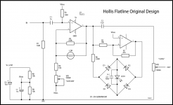
I don't want to reveal just how many hours I've spent on the bench over many, many days trying to make friends with the opto-CdS. Some days I have to walk away, frustrated. My approach has become a "try this" or "try that". I'm still just placing DC voltages across two representative Ge diodes, the LDR LED, external components outside the Ge bridge, components inside the Ge bridge (series and/or parallel), etc. KISS. I don't use the extra amp b/c mine is rail-to-rail. The TL072 isn't. IMO the Hollis circuit can't do anything but provide a brick wall limiter. I see no chance for a linear region especially with that x4.7 "bridging" amp. Every move the main amp makes is differentially quintupled. How does that do anything special re a graceful entry into limiting?
I would love to see your mathematical implementation. of taming the LED-LDR. I have not noticed the long recovery time at low currents. I stay away from the uA region by shunting the LDR with like 10K. Make that thing work a bit.
Lots o' small low-voltage Edison bulbs around. The grain bulbs are kept alive by the dollhouse and model RR industries.
Probably forgot something but don't want to be seen as hijacking this thread....
Attachments
Pity the OP. Not sure if he would any help at all in Building a SS amp.
But the threads are useful for many other things.
Regards.
But the threads are useful for many other things.
Regards.
Wow. Over 200uA of grid current at Vgk=0 for some of those tubes.Here's a snippet of teh Ulrich Neumann, Malcolm Irving data.
It looks like Vgk=(-0.5V) is the threshold above which significant amounts of grid current start to flow.
In a typical 12AX7 stage biased to roughly Vgk=(-1.4V), that means an input signal with a peak amplitude of 1V or more will start to feel the impact of grid current flow.
If the signal peaks at 1.4 volts unloaded, then it will "feel" up to 200 uA of loading. Enough to squash anything coming from a reasonably high source impedance. Even the naked 8k DC resistance of a typical guitar pickup, never mind the inductive reactance or volume control Thevenin impedance.
-Gnobuddy
The thread started many moons ago (Jan 2022), and the OP no longer has a diyAudio profile. 🙁Pity the OP.
I hope he found what he was looking for before he disappeared.
In recent years a lot of people sign up to diyAudio to get help with one single project, then quit. They're not "lifers", they just have one project they want to build.
Nothing wrong with that, at all - I'm not criticizing.
It does have the side effect that diyAudio itself is on borrowed time, particularly when it comes to members with actual technical knowledge and experience.
-Gnobuddy
AFAIK Philips (Netherlands) was decades ahead of everyone else. They seem to have invented the concept of motional feedback applied to loudspeaker drivers, and marketed a couple of speaker designs using it - in the late 1970s!Was it Velodyne who first came out with a servo-controlled sub bass cone DSP?
Ibanez makes several unique models of their own. I think their most successful original designs are popular in the world of shred guitar (and its still-surviving offshoots). They are an old Japanese company, and have been making acoustic guitars for a very long time (about a century): https://reverb.com/news/a-brief-history-of-ibanez-guitarsThanks for your Ibanez info. It does seem like a Gibson wannabee.
I see Gibson as a company that made excellent products up until about sixty-five years ago, around the late 1950s. A few decades later they had sadly morphed into something much more like Harley Davidson. For a long time Gibson have been selling overpriced products with poor quality control, aimed at middle-aged dentists and lawyers with too much money and too little common-sense.
First Ibanez, and then other manufacturers, took advantage of that. I've always liked the ES-335 look, sound and feel, but Gibson's asking prices are ridiculous, and a semi-hollow guitar with an arched and contoured top and back is too complex to build my own. I only have fledgling carpentry and luthier skills.
IMO, for those willing to look beyond the ten-cent decal on the headstock, there are now better products at lower prices made by other companies.
To be fair, I have giant hands and fingers compared to the average person. I'm much happier with guitars with at least 1 3/4" nut width, which are rare in the world of affordable electric guitars. I have a couple of guitars with 1 7/8" nut widths, which fit my hands better....the svelte neck...
Some entry-level Squires have nut widths barely bigger than 1 1/2", and those are virtually unplayable for me. A beginner Cmajor chord will have both the high E and the G strings simultaneously buzzing against the sides of my index finger on the 1st fret of the B string (the "C" note).
Agreed. Too much open loop gain, too much feedback. Brick-wall limiting is exactly what you'll get.IMO the Hollis circuit can't do anything but provide a brick wall limiter.
I've tried a couple of affordable guitar compressor pedals, and always found that they took away too much playing "feel" (dynamics), for that very reason. They just completely squash signal dynamics. Maybe that's why they've never really become as popular as the typical go-to FX pedals every electric guitarist owns.
I plotted LDR resistance vs LED current on a log-log graph, and found that it wasn't too far off from a straight line, over some three or four orders of magnitude.I would love to see your mathematical implementation of taming the LED-LDR.
If you look at it more closely there is definitely some slight curvature to it, but even the crude straight-line fit* isn't terrible, given the enormous manufacturing tolerances of devices like this.
*Straight line on a log-log plot, meaning you're actually looking at a power-law fit function: resistance is proportional to LED current raised to some (negative) power.
That was my starting point. I tweaked it a bit to accommodate the observed slight curvature. I'll post the exact fit function next week, once I'm back at work. (Fighting with COVID-like symptoms now. Yuck.)
I tried that too, in an LTSpice sim of the circuit I want to build.I stay away from the uA region by shunting the LDR with like 10K.
I'm not sure if the parallel resistor is a good idea or not. It adds a kink, a dead-band, to the optocoupler characteristics. Resistance stays very high until there's enough voltage drop across the 10k to light the LED, then resistance plunges abruptly.
Most of the ones I've been able to find are apparently intended for Christmas-tree light strings. Both voltage and current rating are too low for useful tweeter protection.Lots o' small low-voltage Edison bulbs around. The grain bulbs are kept alive by the dollhouse and model RR industries.
You can parallel bulbs to raise current rating. But putting them in series to raise the voltage rating doesn't work quite as well. Because of the positive tempco, the first bulb to heat up immediately raises its resistance, which means it dissipates even more power, which means it gets hotter, which means its resistance goes even higher. So there is a tendency to overload one bulb over the others in the series string. (Probably the reason why Christmas-tree light strings were so very prone to fail.)
For present purposes, I have a Class-D power amp running on a home-brew 5S lithium-ion pack. The amplifier has the usual bridge-mode output that most class-D boards have now.
That means roughly 20V rail voltage, maybe 18V maximum output peaks, or about 13 Vrms maximum sine-wave output voltage to the speaker.
I think a good starting point would be a bulb rated for around 12V - 14V, which may be able to withstand that full RMS voltage without burning out, in case of severe overload. (Automotive dome-light bulb? Tail-light bulb?)
But if heavily overloaded to the point where the output is a 36Vpp square-wave, then RMS voltage equals the peak voltage at 18V, and maybe I really need an 18V bulb? Those are really scarce now, if they're out there.
So much for voltage rating. Then there's the part I really don't know how to do more than estimate crudely: the desired current rating for the bulb. If it's too low, it will be too protective, and the tweeter signal will be heavily compressed. If it's too high, it won't protect the tweeter enough, and it will burn out.
My wild guess is that a typical tweeter voice coil can probably only handle a few watts RMS of sustained power before it overheats and burns out. The voice-coil wire is very thin, the thermal mass very low, and there's no cooling airflow to speak off. All there is, is radiative cooling to the nearby magnet pole-pieces, and maybe ferro-fluid in more expensive tweeters.
If Pmax is a few watts continuous power, that suggests that limiting sustained RMS current to somewhere between 1A and 2A is probably about right, depending on the specific tweeter.
Getting this too far wrong will be a fairly expensive mistake, given the price of a decent tweeter.
-Gnobuddy
Last edited:
Nope, well, maybe back in the very old days when your Tip connected directly to the 12AX7, 1M grid leak R. Dunno when it was but at some point the big-boy amp makers began to insert Grid Stopper Rs before that first 12AX7. Depending on the Input 1 or Input 2 chosen, Tip sees 2x 68K to Gnd with the junction of 68Ks feeding the grid. IOW a series 68K grid stopper + a 68K grid leak + divide-by-two. OR, the other input presents a 1M to Gnd and a parallel combo of 2x 68K (34K) to the grid.Wow. Over 200uA of grid current at Vgk=0 for some of those tubes.
It looks like Vgk=(-0.5V) is the threshold above which significant amounts of grid current start to flow.
In a typical 12AX7 stage biased to roughly Vgk=(-1.4V), that means an input signal with a peak amplitude of 1V or more will start to feel the impact of grid current flow.
If the signal peaks at 1.4 volts unloaded, then it will "feel" up to 200 uA of loading. Enough to squash anything coming from a reasonably high source impedance. Even the naked 8k DC resistance of a typical guitar pickup, never mind the inductive reactance or volume control Thevenin impedance.
-Gnobuddy
Those amps seem to disallow external overdrive from an outside source. The graph from above shows (I think) a low-ohm source (via ammeter) driving the grid w/o a source impedance. The Mullard for example, tested +0.5V @200uA => 2500 ohms. Try to get past even 34K with an outside voltage source with its own Rsource + 34K driving a 2500 ohm destination. Ya gotta get 0.5V across that 2500 ohms. Someone will do the math.
Attachments
Good point about Leonidas Fender and his grid stoppers....at some point the big-boy amp makers began to insert Grid Stopper Rs before that first 12AX7. Depending on the Input 1 or Input 2 chosen, Tip sees 2x 68K to Gnd with the junction of 68Ks feeding the grid.
Merlin Blencowe's noise analysis found that those 68k resistors at the input generate more thermal noise than the rest of the amplifier put together. They dominate the noise of the entire amplifier!
Well-informed amp makers reduce the two 68k resistors and two input jacks to a single input jack with a single series resistor, often in the vicinity of 10k - 12k.
Even if the input RF suppression/grid stopper resistors stop grid current flow at the input stage, I think we have to consider its effect in subsequent triode stages in the audio chain.
-Gnobuddy
Thank you!Typical 1-1/8” tweeter VC can handle 6 watts of average thermal power. 10 watts with ferrofluid.
A 1-amp bulb would limit power to about 4 watts RMS for a 4-ohm tweeter if driven with enough voltage. Too low?
The same 1-amp bulb will allow 8 watts RMS into an 8-ohm tweeter if driven with enough voltage. Mebbe about right (with Ferrofluid)?
There are 10W, 12V bulbs used in automobiles. Current should be about right, if I can still find one of those bulbs (not an LED replacement).
Using your higher 10-watt number, a 1.5 amp (i.e. 18W) bulb would be about right for a 4-ohm tweeter. I haven't found an automotive bulb with the right ratings yet. But there are some 8W bulbs - maybe two in parallel would do the job.
The remaining unknown is the proper voltage rating for the bulb. It has the tweeter impedance in series with it, so it will never see the full output voltage of the amplifier across itself. That means the combination of bulb+speaker can tolerate more voltage than the bulb on its own.
Because bulb resistance is nonlinear with current, I can't calculate this. I probably have to sit down and make some measurements with an 8-ohm power resistor in series with a few different light bulbs, to find out how power in the resistor varies with input voltage. I can do that with a DC power supply, and results should apply to RMS AC voltage.
Running on a 5S lithium-ion pack, in bridge mode, the amplifier should be able to deliver about 20 watts RMS (sine wave) to an 8-ohm tweeter. Up to twice that (40 W RMS) if square-wave. The protection circuit needs to be able to drop that all the way down to 5-10 watts. That means four 32 ohms or 65 ohms total (hot bulb+speaker) resistance, roughly.
That seems like a lot. Maybe a fixed power resistor in series with the speaker, as well as a bulb? Adjust signal levels to balance tweeter with woofer, but the tweeter amp will never be able to drive as much power because of the additional series resistor.
Thanks. I understand that, but still not sure how long we're talking. A second? Ten seconds? More? Less?The more mass in the motor, the longer it will take “more”.
Worst case with a P.A. system is probably a burst of accidental feedback when someone gets a microphone too close to the speaker, and a frequency that is inside the tweeter passband, so the crossover high-pass filter does nothing to help.
I'd like to aim for protecting the tweeter indefinitely under those conditions, so it doesn't fry if it takes me a minute to get to the volume control.
Just thinking out loud, sorry for the stream-of-consciousness post!
-Gnobuddy
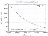
Here is a quick overview. I'm attaching four files that should make it all clear....mathematical implementation. of taming the LED-LDR...
1) The manufacturer datasheet for the NSL-32SR3 includes a tiny R vs I_LED graph that gives an idea of the transfer function, but it's so small and lacking in detail that it's of limited use. Still, you can see that the line is only gently curved, so a power law fit (with a negative exponent) looks plausible.
2) I measured the actual resistance of one of these optocouplers for LED currents from 1 uA to 10 mA. I plotted the data with Gnuplot, started with a likely fit equation, and tweaked it until it fitted. It fits really, really well - data and fit overlap almost perfectly over four orders of magnitude!
The actual equation is printed on the graph. As you can see, it is piecewise linear, consisting of two power-law segments, and a constant.
The fit equation is for resistance in ohms, and LED current in amperes.
Resistance in kilo ohms and current in mA would be more human-readable, but I wanted to make an LTSpice model of the optocoupler using this fit equation - and LTSpice "thinks" in ohms and amperes, so that's what the equation needed to use.
3) The third file is an LTSpice model of a red LED. Years ago, I tweaked it to match the voltage drop of some random red LED I had. Drop it in the same folder as the LTSpice model of the optocoupler itself (coming up next...)
4) The fourth file shows how simple it is to use this fit equation to create an LTSPice model of an NSL-32SR3 optocoupler. I simply plunked down a red LED and a resistor, then right-clicked on the resistor and made its value dependent on the LED current, using the fit equation from step 2.
The LED and current-dependent resistor together now simulate the optocoupler.
If you open up this file with LTSpice, you can run a simulation showing how LED current affects the output voltage from a potential divider made using the optocoupler LDR and a 1-ohm resistor.
You can, of course, drag and drop the LED and LED-current-dependent resistor onto your own LTSpice simulations.
Time dependency of the LDR resistance is NOT simulated. In real life, the LDR resistance changes slowly, taking up to a minute to settle at very low LED currents.
In the simulation, the LDR assumes its final value instantaneously. This means you cannot simulate a compressors attack and decay time constants very well using this LTSpice simulation. Sorry!
I hope this is useful to someone!
-Gnobuddy
Attachments
No use for 25 or 32mm diameter domes here, (which means roughly same size voice coil) but heavy user of self made 14 or 19mm VC cone tweeters, which are mini versions of large speakers.A 1-amp bulb would limit power to about 4 watts RMS for a 4-ohm tweeter if driven with enough voltage. Too low?
The same 1-amp bulb will allow 8 watts RMS into an 8-ohm tweeter if driven with enough voltage. Mebbe about right (with Ferrofluid)?
There are 10W, 12V bulbs used in automobiles. Current should be about right, if I can still find one of those bulbs (not an LED replacement).
Using your higher 10-watt number, a 1.5 amp (i.e. 18W) bulb would be about right for a 4-ohm tweeter. I haven't found an automotive bulb with the right ratings yet. But there are some 8W bulbs - maybe two in parallel would do the job.
The remaining unknown is the proper voltage rating for the bulb. It has the tweeter impedance in series with it, so it will never see the full output voltage of the amplifier across itself. That means the combination of bulb+speaker can tolerate more voltage than the bulb on its own.
Because bulb resistance is nonlinear with current, I can't calculate this. I probably have to sit down and make some measurements with an 8-ohm power resistor in series with a few different light bulbs, to find out how power in the resistor varies with input voltage. I can do that with a DC power supply, and results should apply to RMS AC voltage.
Running on a 5S lithium-ion pack, in bridge mode, the amplifier should be able to deliver about 20 watts RMS (sine wave) to an 8-ohm tweeter. Up to twice that (40 W RMS) if square-wave. The protection circuit needs to be able to drop that all the way down to 5-10 watts. That means four 32 ohms or 65 ohms total (hot bulb+speaker) resistance, roughly.
That seems like a lot. Maybe a fixed power resistor in series with the speaker, as well as a bulb? Adjust signal levels to balance tweeter with woofer, but the tweeter amp will never be able to drive as much power because of the additional series resistor.
Thanks. I understand that, but still not sure how long we're talking. A second? Ten seconds? More? Less?
Worst case with a P.A. system is probably a burst of accidental feedback when someone gets a microphone too close to the speaker, and a frequency that is inside the tweeter passband, so the crossover high-pass filter does nothing to help.
I'd like to aim for protecting the tweeter indefinitely under those conditions, so it doesn't fry if it takes me a minute to get to the volume control.
My go-to protection bulb is a car rear light 12V 15W bulb, so nominally 1.25A, so nominal 12.5W into 8 ohm coils.
Never ever blew any, even in 100/150W keyboard amps, power monitors, or slapper Bass player cabinets.
A few times, musician complains of "no highs" and I find blown bulbs , but then they are doing their job, and besides the inconvenience, much cheaper and quick/easy to replace than the Tweeter itself.
Some high power PA cabinets, notably Traynor or JBL, use 24W 24V bulbs, which means they agree with my "safe current" standard (1A or slightly higher), only they must have blown many 12V ones (we are talking 500-800W cabinets here) and upgraded Voltage rating ... but again not the current.
I bet that sets some kind of unofficial standard.
I'm sorry Gnobuddy, I can't really make sense of your efforts. I am math-challenged. I don't even know what a log-log graph shows you or buys you - in this case. And, you didn't start low enough re LED current. I found the CdS responding @ <1uA on my bench. Crazy. I've tried the ersatz (painted) VTL5C3 and now the ersatz LCR-0202 and LCR-0203 and they all basically share the same DNA, Shunting the CdS with say 10K requires the thing to have fallen below 100K. The two Si diodes + R shunting the LDR LED seem to reduce the LED current appetite by steering/stealing it. The Vf of the Ge bridge is fattening-up a bit, reducing Vled. For me, b/c I don't want a brick wall limiter (that's easy), it's come down to empirical bench time, multi-turn trim pots, etc.
Attachments
Who are those makers? Ya see, my imagined "true over-drive" pedal idea is based on lifting the grid some degree above the headroom against the grid "diode". The advent of series grid resistance pretty much diminished the idea of overcoming that first and then getting say at least 0.3Vg with just a 9V batt with maybe +/- 4V swing and a low impedance Vo. Say 34K into 2.5K = 0.0685 transfer ratio. +4V begets+234mVg. A 12V supply would be better.Well-informed amp makers reduce the two 68k resistors and two input jacks to a single input jack with a single series resistor, often in the vicinity of 10k - 12k.
Thank you very much! That's excellent data.My go-to protection bulb is a car rear light 12V 15W bulb, so nominally 1.25A, so nominal 12.5W into 8 ohm coils.
Never ever blew any, even in 100/150W keyboard amps, power monitors, or slapper Bass player cabinets.
I will be dealing with less than one-tenth of that power, so based on your experience, a 1A, 12V bulb should work fine for me....24W 24V bulbs... 500-800W...
The only difference is I'm hoping I can use a dome tweeter - even more delicate than a cone tweeter.
I don't want or need very high SPL, but do want a relatively smooth and flat treble frequency response. Some of the dome tweeters I looked at do 90 dB @1W @1m, and if they will handle 10 watts, that means 100 dB @ 1 m. I think that will be more than loud enough for my purposes (jamming with a handful of amplified electro-acoustic guitars and one electronic keyboard, no drums).
-Gnobuddy
Sorry, I completely misunderstood - I thought you were an EE, and so I made no attempt to explain that rather technical post.I don't even know what a log-log graph shows you or buys you - in this case.
I can explain in non-math terms. The almost-straight log-log graph tells us that the optocoupler responds to ratios, rather than differences.
A linear response would mean that an increase of "x" milliamps would produce a reduction of "y" ohms. For example, every milliamp increase in LED current would produce, say, a 10 kilo-ohm reduction in resistance.
But that's not what the optocoupler does. Not even close.
What it actually does is this: at low LED currents (below, say, 20 uA), every time you double the current, the resistance drops to approximately one-fourth of its previous value.
Another way to say that: if the LED current increases by 6 dB, the LDR resistance drops by 12 dB.
As the LED current gets bigger, the resistance doesn't drop as fast for every doubling. By the time you get to roughly 200 uA and more, the resistance only halves for every doubling of LED current. That means, for LED currents above roughly 200 uA, a 6 dB increase in LED current only causes about a 6 dB drop in LDR resistance. (Not a 12 dB drop.)
At currents in between 20 uA and 200 uS, response is somewhere in between.
I also saw the LDR in the optocoupler I used respond to changes that small - but LDR resistance was already eight million ohms at 1 uA LED current. It was also very slow to respond - it took several minutes (!) to settle after each current change.And, you didn't start low enough re LED current. I found the CdS responding @ <1uA on my bench.
In short, for my purposes, LDR resistance was too high to be useful, and LDR response was too slow to be useful, at 1 uA LED current.
I won't get into it, but measuring currents below 1 uA with any accuracy requires specialized equipment. An ordinary DMM won't cut it.
It takes roughly 1.8V to light a typical red LED, and each silicon diode drops roughly 0.6 volts, so there needs to be about 3 volts DC across the bridge before the LED will light. When the input signal reverses polarity, the poor op-amp has to try to instantly produce -3V before the LED will light.The two Si diodes...
There is a huge "dead zone" that the output of the second op-amp has to traverse before the LED gets any current. Since the op-amp cannot slew its output instantly from +3V to -3V, the frequency response of this part of the circuit (2nd op-amp, diode bridge, LED) will be very poor.
If you're also powering the op-amp from only 9 volts, the situation becomes very marginal. A TL072 can barely manage +/- 3V output when its running on 9V. The op-amp will saturate before the LED is fully lit.
At the same time, that "dead zone" is what sets the threshold above which compression starts. The "knee" of the compressor.
You want softer compression? Increasing VR1 is not doing the job? In that case, my suggestion is to try reducing the voltage gain of the rectifier part of the circuit. That means reduce R7.
This will have the side effect of also raising the threshold voltage (compressor knee), in addition to reducing the compression ratio.
The only way to compensate for this is to add one more op-amp gain stage, before the input. Adjust the gain of that stage to get the "knee" where you want it. Increase VR1 and reduce R7 to tone down the brick-wall limiting above that knee.
In my twenties, I tried more than once to design and build a DIY guitar compressor. All of them worked, i.e. they did compress, but all had unpleasant side-effects which I did not like.
Later I tried an Alesis NanoCompressor, which has all four of the controls a compressor should: attack time constant, release time constant, threshold, compression ratio. It's a nice little compressor with a good reputation, but I still couldn't learn to love it (for guitar).
-Gnobuddy
- Home
- Live Sound
- Instruments and Amps
- Building a SS guitar amp