I Tried (simulations) the BA-3FE but its output impedance was too high to drive the capacitance of the SIT without a lot of distortion. Also, with my higher rail voltages, the JFETs must be cascoded. The FE shown in post #157 has has no degeneration of the Toshiba FETs due to the connections of C6 and C7, and has very high gain (> 40dB), requiring negative feedback to achieve the an overall gain of 10X. By connecting C6+ to the positive rail, C7- to the negative rail, and removing the feedback resistor R20, you get the BA-3FE topology, except for the cascodes. Of course, various resistor values must be changed to get the desired gain. Bottom line: without feedback the output impedance was too high to achieve my distortion goals.
I also looked at using a complementary folded cascode circuit, similar to that of John Curl's Blowtorch, but its output impedance is even higher. If a follower stage with low output impedance were added it would be a good candidate. The main challenge there is in biasing the follower FETs without requiring degeneration.
If no voltage gain is needed to drive your 600R:600R transformer, then a follower buffer with more current drive would work. If gain is needed, something totally difference is required.
The ACP+ as an FE might works, but some redesign would be needed for higher rail voltages, and the distortion levels might not meet your needs.
what's simulated behavior of shown OS, during powering On and powering Of sequences, regarding DC Offset (spike?) and Iq ramping?
there is no problem visible, when you have C02 in place ( and of course that you need it)
everything up to 2V5, as peak on output, is acceptable, as long it is not too abrupt
so just chill 🙂
just for (necessary) fun - check power off behavior, same as Iq stability- after 5-10sec burst of , say, 70% of full power
on 50Hz, on 1KHz and on 10KHz
everything up to 2V5, as peak on output, is acceptable, as long it is not too abrupt
so just chill 🙂
just for (necessary) fun - check power off behavior, same as Iq stability- after 5-10sec burst of , say, 70% of full power
on 50Hz, on 1KHz and on 10KHz
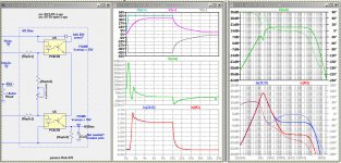
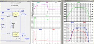
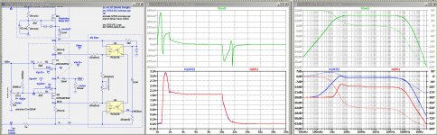
The first image below shows the power on/off behavior of the circuit shown in post #157 and the AC analysis. The "thump" in Vout is quite acceptable, but the AC analysis is troubling at low frequencies. That problem is due to a pole created by the combination of Co2 and Cx driving the gate of PFET M1, which is totally eliminated by removing Co2. But eliminating Co2 creates serious power up/down thumps as shown in the send image.
I am trying to figure out a way to switch out Co2 after a time delay. Any suggestions?
I am trying to figure out a way to switch out Co2 after a time delay. Any suggestions?
Attachments
I tried that but it doesn't help. I also tried using a cap. multiplier on the negative rail, with the same results.The problem is that the SIT Vgs needs to reach -5.9V to limit the current.What about slowing down the cap multiplier for startup?
Great minds running in the same circles. 😉
I was thinking 220 uF across the C-E of each optocoupler. Perhaps can eliminate Co2.
I was thinking 220 uF across the C-E of each optocoupler. Perhaps can eliminate Co2.
Last edited:
speak for your self 
this mind is occupied making all possible mistakes..... trice..... and then some impossible ones
reminds me of, sorta recently, completing perfect output amp, already on perfect set of (as established) final!! pcbs, just to find out that amp is not just able but also trying hard, to kill even 2KW 18" speaker, while powering offfffffffffff

Transient behavior is rather difficult to determine, and get a good correlation between simulation and real-world. My LT-Spice Fu is pretty rusty, so I'm going to delay that analysis for even later.
I've been wanting to build a decent XA25-like beast for a while now, and feel like I have a reasonable understanding of the front end. However, the published diagrams all seem to have a fetish for components that are no longer in production. I'm happy with the Linear Systems versions of the K170 and J74, and Punkydawg still has NOS critters, so far so good there. However, the 2SC4793 and 2SA1837 don't seem to be available anywhere, and I don't like resorting to Ebay for the 2SK2013 and 2SJ313.
In place of the 2SC4793 & 2SA1837, I would like to propose the TTC004B and TTA004B. I have used these in a couple places already with good results; the most recent being the revised front end of my F6. The 2SK2013 and 2SJ313 might be replaced by he FQP4N20L and FQP3P20, as these seem to work well in the BA-3 pre. Some revision would no doubt be necessary to the bias adjustment.
Where I get to going around in circles is the thought of using some good old timey lateral Mosfets to replace the K2013 and J313. I happen to have matched pairs of the original Hafler laterals that were pulled from working amps. I also have a matched set of NOS Exicon 10N16 and 10P16 laterals from an early project before I started collecting whole amps. No longer in production, but the newer 200V equivalents are. Might be fun.
Last edited:
all buttons pressed 🙂
one of main functions of this forum - it's brain enabler
and, more we use the brain , Papa's green is broader, he's working in better mood, being more efficient , thus laying out more food for brain
one of main functions of this forum - it's brain enabler
and, more we use the brain , Papa's green is broader, he's working in better mood, being more efficient , thus laying out more food for brain
Seems to be moving in the right direction.
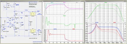
The tricky aspect of biasing this output stage is that the two big devices have different gate threshold characteristics, but get their bias voltage from the same source. The resistor divider made with a trim pot just sets a voltage offset, but the two gates track each other otherwise.
The tricky aspect of biasing this output stage is that the two big devices have different gate threshold characteristics, but get their bias voltage from the same source. The resistor divider made with a trim pot just sets a voltage offset, but the two gates track each other otherwise.
... However, the 2SC4793 and 2SA1837 don't seem to be available anywhere...
2SA1837L-TF3T Power Transistor -230V -1A | Profusion
2SC4793LB-TF3T Power Transistor 230V 1A | Profusion
They are available somewhere. 🙂
Cool, those didn’t show in my search.
I still like the Toshiba TTC004B and TTA004B in those locations for the XA25 front end.
I still like the Toshiba TTC004B and TTA004B in those locations for the XA25 front end.
Last edited:
Seems to be moving in the right direction.
The tricky aspect of biasing this output stage is that the two big devices have different gate threshold characteristics, but get their bias voltage from the same source. The resistor divider made with a trim pot just sets a voltage offset, but the two gates track each other otherwise.
What makes it hard it that the SIT (JFET) starts up in the turned on state while the PFET is turned off.
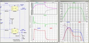
Here is a complementary folded cascode, non-feedback front-end that looks promising. At 28V peak outout, the THD is <0.02% into a 500R load shunted by 10nF capacitance. There are details yet to be revolved for controlling the bias to the follower stage, and tweaks to parameter values.
Since Nelson doesn't count cascodes, after adding the output stage there would be only 3 gain stages, but I am not sure whether the folded cascode should be counted as a gain stage or not. But the result would be a very low distortion 50W amplifier without any feedback loops. I haven't yet done a simulation of the complete amplifier.
Since Nelson doesn't count cascodes, after adding the output stage there would be only 3 gain stages, but I am not sure whether the folded cascode should be counted as a gain stage or not. But the result would be a very low distortion 50W amplifier without any feedback loops. I haven't yet done a simulation of the complete amplifier.
Attachments
Last edited:
not that I'm overly concerned with number of stages,generally, if there is objective need for using additional one , but I think that cascode Pa would count as 1/2 stage 
- Home
- Amplifiers
- Pass Labs
- SIT measurements, Mu Follower, and amplifier build