I have been using the TIP31C and TIP32C in the SIT3X folded cascode front-end. One of the three PCBs using these parts shows a much higher PSRR (sensitivity to ripple of the rails). I started looking carefully at the SPICE models for the parts and the Early voltage for the TIP parts is about a factor of about 30 lower than for MJE15032/MJE15033, KSC3503DS/KSA1381, 2SC4793/2SA1837 BJTs. With good matches between the Early voltages of PNP and NPN the effects will cancel in this complementary circuit, but an imbalance will degrade the PSRR.It's a generic part, nothing special. I recently used some TIP31 and 32.
Very interesting thread! Why not bjt CFP for lower voltage drop?I have been working on a variation of a low dropout capacitance multiplier based on one used by Mr Evil. It is not a simple as the "easy cap multiplier," but it has very low dropout by virtue of using a low RdsOn P-channel Mosfet.
Schematic is the positive portion of the attachment.
For the SIT3X output stage, some adjustments can be made:
R1 and R2 are 22k. C5 is 100 uF, preferably a low impedance organic polymer.
Q1 and Q2 are KSA992, grade F. X1 and X2 are ZVP3310A.
J1 can be a simple CRD such as E-562, taken to ground instead of the negative rail.
X5 is a IXTH52P10. R5 should probably be 47 Ohms.
R7 is 100k, RV1 is 100k, R8 is 220k.
C9 is 100 uF, same as C5. Add 4700 uF to 10,000 uF as needed for energy storage.
A protection diode should be added from the Drain to Source of X5. Probably 1N4003.
I have made good use of Bipolar CFP regulators or "ripple eaters" depending on the needs of the power supply. They are quite good as tracking regulators.
The circuit I described in the quoted text has even lower dropout voltage capability by using a P-channel Mosfet as the pass element. This is actually a more traditional voltage regulator that has a fixed output voltage.
The circuit I described in the quoted text has even lower dropout voltage capability by using a P-channel Mosfet as the pass element. This is actually a more traditional voltage regulator that has a fixed output voltage.
I am very interested in the schematics in the post#119.
I always think what we are listening in DEFiSIT? We are listening more SIT or more Mosfet?
I always think what we are listening in DEFiSIT? We are listening more SIT or more Mosfet?
In my initial posts of this thread I showed extensive measurements of six 2SK182ES SITs and presented plots of "sweet spot" behavior. What I did not do was derive the parameters needed for accurate SPICE simulation.
Using the Michael Rothacher SIT model ("A concise model for Static Induction Transistor IV characteristics Linear", Audio Vol. 6), I developed least squares code in GNU Octave (MatLab clone) to solve for the SIT model parameters to best fit the FrankenTracer data.
The a given SIT, the model has constant parameters K, Vct, N, MU, and X, and functional form:
Id(Vgs, Vds) = K*max(0,(Vgs+Vct+N*log(Vds)+Vds/MU))^X
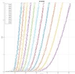
In the first plot, the "raw" FrankenTracer data captured from my Rigol DS1054Z digital scope is shown as dots. The "ragged" nature of the data is due to quantization by the scope's 8-bit ADC. The solid lines show the data after smoothing is applied.
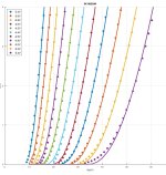
In the second plot, the smoothed FrankenTracer data is shown as dots. The solid curves show the SIT model least-squares fit to that smoothed data. The SIT model parameters for 2SK182ES#4 are:
From the Rothacher SIT model is is easy to compute the small signal triode parameters of the SIT at a given operating point.
The triode parameters for 2SK182ES#4 at Vds=30V, Id=1.5A are:
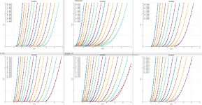
The final plot shows a collage of the Rothacher SIT model fits for all six 2SK182ES SITs.
The least-squares model fits look very good except at the low Id drain currents. There are several possible explanations for this:
My instrumentation Id measurements have a bias offset.
The Rothacher SIT model doesn't capture the load current behavior.
My least-squares fitting isn't properly weighted.
For practical purposes, I am very happy with these results.
Using the Michael Rothacher SIT model ("A concise model for Static Induction Transistor IV characteristics Linear", Audio Vol. 6), I developed least squares code in GNU Octave (MatLab clone) to solve for the SIT model parameters to best fit the FrankenTracer data.
The a given SIT, the model has constant parameters K, Vct, N, MU, and X, and functional form:
Id(Vgs, Vds) = K*max(0,(Vgs+Vct+N*log(Vds)+Vds/MU))^X
In the first plot, the "raw" FrankenTracer data captured from my Rigol DS1054Z digital scope is shown as dots. The "ragged" nature of the data is due to quantization by the scope's 8-bit ADC. The solid lines show the data after smoothing is applied.
In the second plot, the smoothed FrankenTracer data is shown as dots. The solid curves show the SIT model least-squares fit to that smoothed data. The SIT model parameters for 2SK182ES#4 are:
MU = 133.57
N = 1.2592
K = 4.6096
Vct = 0.7153
X = 2.4821
From the Rothacher SIT model is is easy to compute the small signal triode parameters of the SIT at a given operating point.
mu(Vds) = 1/(1/MU+N/Vds)
gm(Id) = Id*X/((Id/K)^(1/X))
Rd(Vds,Id) = mu(Vds)/gm(Id)
Rd(Vds,Id) = (Id/K)^(1/X)/(Id*(N/Vds+1/MU)*X)
The triode parameters for 2SK182ES#4 at Vds=30V, Id=1.5A are:
mu = 20.219
gm = 5.8525 Siemens
Rd = 3.4548 R
The final plot shows a collage of the Rothacher SIT model fits for all six 2SK182ES SITs.
The least-squares model fits look very good except at the low Id drain currents. There are several possible explanations for this:
My instrumentation Id measurements have a bias offset.
The Rothacher SIT model doesn't capture the load current behavior.
My least-squares fitting isn't properly weighted.
For practical purposes, I am very happy with these results.
Attachments

Here are th3 Rothacher SIT model parameters and triode parameters at Vds=30V Id=1.5A for all six 2SK182ES SITs.
Name Sigma MU N K Vct X
SK182ES#1 0.0365 59.58 1.4637 4.9099 0.2980 2.3149
SK182ES#2 0.0577 73.28 1.5387 0.6577 0.8468 3.8636
SK182ES#3 0.0337 82.45 1.2228 5.0271 0.5103 2.5174
SK182ES#4 0.0643 133.57 1.2592 4.6096 0.7153 2.4821
SK182ES#5 0.0809 81.60 1.3055 3.1070 0.6332 2.5260
SK182ES#6 0.0452 63.91 1.2502 6.4354 0.4292 2.0000
Triode Parameters at Vds = 30.00(V) Id= 1.50(A)
Name mu gm(S) Rd(Ω) Vgs(V)
SK182ES#1 15.2501 5.80 2.63 -5.1805
SK182ES#2 15.3993 4.68 3.29 -5.2519
SK182ES#3 18.9074 6.10 3.10 -4.4147
SK182ES#4 20.2185 5.85 3.45 -4.5865
SK182ES#5 17.9301 5.05 3.55 -4.6916
SK182ES#6 17.4455 6.21 2.81 -4.6680
An important note: In the past, all of my simulations of the 2SK182ES have been used the following Spice model, whose parameters result in much lower MU and gm values than my actual SITs.
model params: MU=16.98; X=2.56; K=0.443; N=1.6; Vct=0
triode params: mu = 8.9106 gm = 2.3846 Rd = 3.736 Vgs = -5.5984 at Vds = 30V, Id = 1.5A
Name Sigma MU N K Vct X
SK182ES#1 0.0365 59.58 1.4637 4.9099 0.2980 2.3149
SK182ES#2 0.0577 73.28 1.5387 0.6577 0.8468 3.8636
SK182ES#3 0.0337 82.45 1.2228 5.0271 0.5103 2.5174
SK182ES#4 0.0643 133.57 1.2592 4.6096 0.7153 2.4821
SK182ES#5 0.0809 81.60 1.3055 3.1070 0.6332 2.5260
SK182ES#6 0.0452 63.91 1.2502 6.4354 0.4292 2.0000
Triode Parameters at Vds = 30.00(V) Id= 1.50(A)
Name mu gm(S) Rd(Ω) Vgs(V)
SK182ES#1 15.2501 5.80 2.63 -5.1805
SK182ES#2 15.3993 4.68 3.29 -5.2519
SK182ES#3 18.9074 6.10 3.10 -4.4147
SK182ES#4 20.2185 5.85 3.45 -4.5865
SK182ES#5 17.9301 5.05 3.55 -4.6916
SK182ES#6 17.4455 6.21 2.81 -4.6680
An important note: In the past, all of my simulations of the 2SK182ES have been used the following Spice model, whose parameters result in much lower MU and gm values than my actual SITs.
*GENERATED BY SIT MODELER @ AUDIOHOBBY.COM by Generg
*MODEL RANGE: 80V, 2A
.SUBCKT 2SK182ES2 D G S ; Drain Gate Source
+ PARAMS: MU=16.98 X=2.56 K=0.443 N=1.6 VCT=0 RG=2MEG
*--------------------------------------------------
B1 D S I=K*PWR(URAMP((V(G,S)+VCT)+(N*LN(V(D,S))+(V(D,S)/MU))),X)
FOR MULTISIM COMMENT OUT ABOVE LINE () AND UNCOMMENT NEXT LINE
*B1 D S I=K*PWR(MAX((V(G,S)+VCT)+(N*LN(V(D,S))+(V(D,S)/MU)),0),X)
R1 G S {RG}
CGS G S 17.7nF ; Ciss-Crss
CGD G D 10nF ; Crss 10nF is wild guess need a measured value here
CDS G S 10nF ; Coss-Crss 10nF is wild guess need a measured value here
.ENDS 2SK182ES2
model params: MU=16.98; X=2.56; K=0.443; N=1.6; Vct=0
triode params: mu = 8.9106 gm = 2.3846 Rd = 3.736 Vgs = -5.5984 at Vds = 30V, Id = 1.5A


- Home
- Amplifiers
- Pass Labs
- SIT measurements, Mu Follower, and amplifier build