I re-read the Chapter 6 and it makes much, much more sense to me now (even though the math itself is still above my head to a large extend). It's almost an intuitive reading now 🙂
It states (p.145), among other things:
"If instead of driving the throat with a wavefront of constant amplitude we taper this amplitude as shown in Fig. 6-12, then the net effect will be to create adistribution of the velocity at the mouth which has a far more uniform distribu-tion than one fed with a flat throat velocity distribution"
Would it make sense then to try to damp the phase plug exit this way? I'm thinking about putting an open cell foam (the right amount and density) into the exit rings openings. The 18Sound ND4015 seems like a good candidate - laying on my bench right now. It has four slits for a 1,4" throat, reaching the exit of the driver.
Last edited:
Another excerpt (p.148):
"...The only way for this higher order mode creation to not occur would be for there to be a wavefront radius source point which did not move in space, as opposed to one that is changing in each section. It is now readily apparent that any waveguide which has a changing location of the origin for the wavefront radius will require the presence of higher order modes to account for this changing origin."
It seems that this (i.e. the wavefront origin shifting) is exactly what happens for larger throats. For a smaller throat it takes less of the contour to approach a cone, more for the larger.
Now when I think about it more, it can't be the explanation as simply as it is stated. By this reasoning a straight cone directly connected to a flat wavefront would be even better, which I assume is not.
Last edited:
sorry to butt in but as the math is dumfounding to me, i hope i can ask a few questions to gain some understanding (and hopefully start to make a math to english bridge for myself)
currently these equations are plotting a particular curvature with the intent of doing so with a minimum of problems in the field of interest(i.e. a field defined by the directivity) or am i out to lunch?
currently these equations are plotting a particular curvature with the intent of doing so with a minimum of problems in the field of interest(i.e. a field defined by the directivity) or am i out to lunch?
These equations (if you mean what I have presented) are just an attempt to cover the whole WG contour in one formula, as smooth as possible. Just a mathematical exercise, really. It has no status of being optimal in any sense... It's not bad either.
That would lead me to an idea of making a secondary phase plug to be put at the exit of the existing one that would transform the "flat" wave (hopefully) emanating from a driver into spherical. Maybe it is just nonsense...
The wavefront of an 18Sound 4015Ti/Be is practically spherical at the exit.
This was confirmed by 18Sound to someone I know.
You could enquire once more to be sure.
I have no clue about the radius.
You could enquire once more to be sure.
I have no clue about the radius.
Last edited:
Would it be too much hassle to pinch the 2" throat to 1" and stretch the throat accordingly?
It is then of course no longer an OS throat, but I wonder what the sims would look like.
It is then of course no longer an OS throat, but I wonder what the sims would look like.
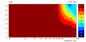
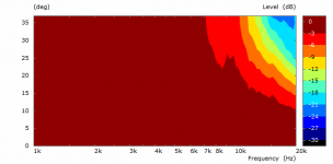
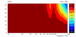
I tried the step-tappered throat amplitude but not much of improvement so far. Maybe the exact wavefront profile is much more critical than I anticipated.
(2" throat, 75deg coverage; from left: flat, taperred(1), tappered(2))
(2" throat, 75deg coverage; from left: flat, taperred(1), tappered(2))
Attachments
In the most basic sense we all (I guess) use to judge the performace of a loudspeaker based on measured data - if you look at the polar maps presented, they just could be much worse - less constant directivity and more of diffraction or even a presence of resonances.in what sense is it not bad either? i'm trying to understand...
Last edited:
hey...thanks...just conjecture on my part but but given modern computing power would it be possible to convert the information obtained in a polar map(visual) into a audible algorithm for auditory evaluation i.e. hear the results of shape changes to horn curvature?
must be a language thing but to me it's "unfortunate"....dsp..FIR...seems something could do it...it would be invaluable to evaluate the audible results of all the horn math....
I find that unlikely. What's the radius then?
I agree. That is not what virtually all CDs try to do, so I don't see how or why this would be the case here. It seems to me to be almost impossible to achieve and almost as difficult to prove.
Which brings me to where I think the research should go from here. One of my last project at B&C was to develop a plane wave tube measurement of the exit waveshape. I worked out all the math, but the system was never implemented to my knowledge.
With measurements like this we would know exactly what we have at this interface and may be able to better optimize a waveguide for the actual situation and not an assumed one.
I tried the step-tappered throat amplitude but not much of improvement so far. Maybe the exact wavefront profile is much more critical than I anticipated.
(2" throat, 75deg coverage; from left: flat, taperred(1), tappered(2))
Did you just shade the amplitude? Is there phase shift as well?
I do see some substantial effects even with what you showed. I would not expect a huge effect even best case. We are talking about 2nd order effects here.
One of my last project at B&C was to develop a plane wave tube measurement of the exit waveshape. I worked out all the math, but the system was never implemented...
How did this work? I don't mean the math but what was the measurement set up?
JBL explicitly tout the flat exit wave shape of the D2430K compression driver (used in their M2 reference monitor).
They do show some plots to support the claim but I have never seen any information on how they measured it.
I did wonder if a Microflown had been tried.
Best wishes
David
Put a CD on a plane wave tube with known nonreflective termination. B&C had one of these, they wrote a paper on it. Place N microphones at Xn distances. From the math you can find one mode for each microphone N. Its a matrix problem that is almost certainly unstable and near singular at certain frequencies, but with SVD this could be done, but it would likely add a few mics to get an overspecified matrix.
I imagined electrodes connected to one's brain to "listen" how the horn would sound in real (and fortunately we are not that far yet)... Otherwise I don't think it's possible to emulate that with electronic filters only.must be a language thing but to me it's "unfortunate"....dsp..FIR...seems something could do it...it would be invaluable to evaluate the audible results of all the horn math....
Just the amplitude. I tried the range 1 -> 0,5-0,8 with various steps. Some was better, some worse. I want to try this on a real driver some day.Did you just shade the amplitude? Is there phase shift as well?
I do see some substantial effects even with what you showed. I would not expect a huge effect even best case. We are talking about 2nd order effects here.
- Home
- Loudspeakers
- Multi-Way
- Acoustic Horn Design – The Easy Way (Ath4)