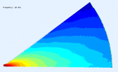
How do you achieve so smooth BEM results? I still can't get rid of various defects no matter what I do. Do you use any smoothing on the observation level? That could explain some differences at the lower frequencies, like 3 kHz, where I wouldn't expect any noticable difference, given the miniscule differences in the contour.
The difference is really quite noticeable this time. It's surprising to me.
The difference is really quite noticeable this time. It's surprising to me.
Attachments

Last edited:
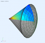
No smoothing. Those are 3D simulations, which seem to give smoother results for some reason (but obviously take much longer to run). Occasionally I'll see strange blips, but I can usually get rid of them by changing parameters very slightly.
Coincidentally, I recently finished adding SVG export to my waveguide script to do simulations with Dim=CircSym, and I'm getting anomalies similar to what I see in the data you've posted recently.
Coincidentally, I recently finished adding SVG export to my waveguide script to do simulations with Dim=CircSym, and I'm getting anomalies similar to what I see in the data you've posted recently.
Ah, 3D simulations. It's a pity that CircSym seems can't work that well. It would save a huge amount of time.
- Now, the question is: Is it possible to further reduce the axial ripple by using a non-axisymmetric mouth? I'd think so but I'll leave it as an exercise for the readers 🙂
- Now, the question is: Is it possible to further reduce the axial ripple by using a non-axisymmetric mouth? I'd think so but I'll leave it as an exercise for the readers 🙂
With reference to the last few posts, which have helped to settle my understanding:
#319 is extremely helpful. Despite Earl's work and the BEM (etc.) simulations, there appears to be quite a lot of distraction/confusion about how best to consider HOMs.
It is useful to be reminded that the free space spherical harmonics form the most appropriate basis set in terms of the desired outcome - in the listening area.
Waveguides based on OS, as simulated in the last few posts, might be close enough to the ideal to allow the mode decompositions to be relatively "clean" (judging from the remarkably clean results in #320).
From#320, without doing any calculations, and having read Earl's work, I take it that the feature at about 5.6kHz corresponds to the lowest order, symmetric*, HOM for the "OS waveguide". That would leave the 2.1kHz feature to arise from the lowest symmetric HOM predominantly due to the geometry of the mouth-baffle transition. In a real speaker there would of course be other transitions at the baffle edge, etc.
It can be seen in #320 that the mouth termination substantially affects the 5.6kHz feature - no surprise given the geometry/scale relative to the wavelength.
[Numerically] evaluating the mode decomposition of the free space wave into spherical harmonics could be interesting. I.e. to find the complex (mag/phase), frequency dependent, coefficients of the dominant terms. Since there are not very many HOMs in the important sub-10kHz band, it's only a handful of frequencies that to need be evaluated (assuming that they can be chosen to correspond well enough to those at which each HOM is strongest, which from the simulations it looks as if they can).
*there should be a lower order asymmetric mode, but that's not excited as the simulation is symmetric. That could become important, in principle, though perhaps not in practice, for real horns made with finite precision and with input wavefronts not perfectly axial and to some degree tilted.
Ken
I read most threads about waveguides, out of curiosity, but post very rarely.
My impression allways was that much of what is seen on a far field polar map is really mouth related. For that reason I would like to separate the issue - to have a separate look on the OS contour related HOMs (without a termination) and the rest.
Could a phase plug be made so that it produced a spherical wavefront? If so, it could be connected to a straight (conical) horn. Regarding HOMs, would it then be any better or worse than OS contour driven with a flat wavefront?As far as acoustic lense goes: I did my MS Thesis on them, made several. They don't work very well - at best - and they take a lot of space to do much. It's very hard to get a large enough index of refraction to make much curvature.
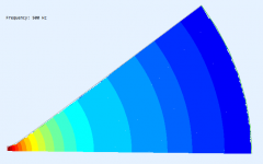
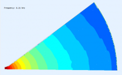
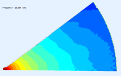
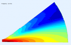
How do you achieve so smooth BEM results? I still can't get rid of various defects no matter what I do. Do you use any smoothing on the observation level? That could explain some differences at the lower frequencies, like 3 kHz, where I wouldn't expect any noticable difference, given the miniscule differences in the contour.
The difference is really quite noticeable this time. It's surprising to me.
I also faced "noisy curves" problem both in ABEC3 and AxiDriver. As follows from the ABECs manual, it seems that it is a general BEM problem encountered in external radiation problem. ABECs manual describes it as the Non-Uniqueness Problem (NUC). You can try to remove the NUC by specifying the true/false value of the "NUC=" parameter under Control_Solver script (for problems that doesn't exploit symmetry properties)
e.g. Breathing sphere from ABECs example folder

But I have no noticed that "NUC=true" does any effect when any value of "Sym=" is specified

Last edited:
Could a phase plug be made so that it produced a spherical wavefront? If so, it could be connected to a straight (conical) horn. Regarding HOMs, would it then be any better or worse than OS contour driven with a flat wavefront?
Opening up the phase plug for consideration changes things immensely. I am sure that what you suggest could be done in principle. You should first read my patent on proper phase plug design (because most are done wrong,) as well as the discussion in my book about how one could suppress HOMs through phase plug design.
The problem, of course, is that we, as DIY, have no control over the phase plug. It is what it is.
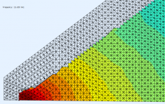
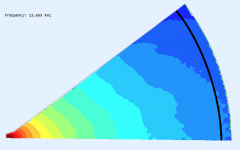
BTW, it seems in principle possible to inspect wavefronts in the contour itself, without a termination (i.e. with a fully damped one). If only the BEM was reliable - this is still only for the CircSym so I guess there is still a lot of clutter. A full 3D sim could give a cleaner picture but would take eternity to run.
(The ragged edge is caused by the way the fileds are meshed, it should not be a problem.)
(The ragged edge is caused by the way the fileds are meshed, it should not be a problem.)
Attachments
That would lead me to an idea of making a secondary phase plug to be put at the exit of the existing one that would transform the "flat" wave (hopefully) emanating from a driver into spherical. Maybe it is just nonsense......The problem, of course, is that we, as DIY, have no control over the phase plug. It is what it is.


Last edited:
So if I get it right - now if I took the velocity along the black line and made the spherical harmonics decomposition, I would get amplitudes (and phases) for all the modes produced by the device itself, before reaching the mouth flare? At what distance from the throat? I guess it should be really before the real world termination.
Attachments
Last edited:
That would lead me to an idea of making a secondary phase plug to be put at the exit of the existing one that would transform the "flat" wave (hopefully) emanating from a driver into spherical.
It's called an OS waveguide.
So if I get it right - now if I took the velocity along the black line and made the spherical harmonics decomposition, I would get amplitudes (and phases) for all the modes produced by the device itself, before reaching the mouth flare? At what distance from the throat? I guess it should be really before the real world termination.
The problem is finding the "real world" termination. A perfectly absorbing boundary is not accurate if one is close to the source. You have to be out some distance. This problem was addressed some (many) years ago in an AES paper that I worked on with Prof. Porter.
But your sims clearly show how the 2" is beaming - more HOM contribution - at an ever lower frequency - just as predicted and found in reality.
That's what I was asking 🙂 So there is no better way.It's called an OS waveguide.
None that I know of.
In general forcing waves to do things is not nearly as effective as allowing them to do what they have to. By this I mean that the big difference in my approach from virtually all other approaches to horn shapes, is that others try to force the waves to conform to some desired shape. I took the approach of trying to find that shape which best allows the wavefront to do what I want.
I have to laugh when I see drawings of waveguides with the wavefronts drawn in as if the wave is going to do that just because the designer wants it to!! It's absurd!
And by the way - I find your understanding the situation almost without parallel. Most of what has been written about horns/waveguides is either wrong or misguided. You certainly understand what the problem is and how one has to go about solving it. Very few have this understanding.
PS: An elliptical waveguide mouth takes the axial hole and spreads it. It doesn't go away completely, but it does get less deep, but broader. That is probably better, but as a few have noted who tried this, it adds a lot of complexity with an almost insignificant improvement. I had hoped it would be a God-send, but in the end it was just a lot more problems.
PS: An elliptical waveguide mouth takes the axial hole and spreads it. It doesn't go away completely, but it does get less deep, but broader. That is probably better, but as a few have noted who tried this, it adds a lot of complexity with an almost insignificant improvement. I had hoped it would be a God-send, but in the end it was just a lot more problems.
Last edited:
Someone mentioned earlier in this thread the possibility of making phase plugs from photoresin printing. From what I remember, JBL actually ended up making phase plugs using this method for production components (I think for one or two of their beryllium diaphragm compression drivers).The problem, of course, is that we, as DIY, have no control over the phase plug. It is what it is.
Given a tool like the Formlabs Form 3, homemade phase plugs are not out of the question.
- Home
- Loudspeakers
- Multi-Way
- Acoustic Horn Design – The Easy Way (Ath4)