A top-slot carrier board for the ODAC rev B
I had planned on making a top-slot board for the ODA where the ODAC could be mounted from the start of this project. But I had read enough posts over the years where people were having very occasional random problems with the ODAC board that I hadn't been willing to make the board unless a galvanic isolator for the ODAC was included. Designing a galvanic isolator was more than I've wanted to get into.
But now that George has released the new version B of his ODAC
http://www.diyaudio.com/forums/head...headphone-amp-diy-project-87.html#post4325434
and the pesky problem has been tracked down - the occasional PC USB port with ceramic capacitors on it that resulted in the ESR being too low, causing the ODAC's LDO to oscillate - I'm going to go ahead and make the top slot carrier board. 🙂 No galvanic isolator needed. The ODAC board is powered from the PC's USB bus of course. It doesn't hook into the ODA's power supply.
There is not much to see here, below. Just a blank PC board that slides in the top slot of the ODA, with the three 3 mm mouting holes for the ODAC. I've specified a 5mm hole to allow the twisted pair audio wires to pass from the ODAC to the ODA. The ODAC audio wires can go to the PCB holes by either the 3.5mm jack or the rear panel RCA jack. Best to wire the ODAC into whichever jack you use the least.
Please post if anyone has thoughts about changes or additions to the board. With this design the USB port will be in back of the unit. The vent holes that are on the most recent set of rear panel FPE CAD files at the google link all sit below the level of the top slot board, allowing the output chips' heat to still escape by convection without heating up the ODAC board.
I'll add a cutout to the rear panel CAD file for the USB connector. The connector is a tiny mini USB so a hole can simply be drilled for it on exsiting rear panels. I'll post the X,Y locations of the hole. I'm going to have this board fabricated, but since it doesn't contain any traces it could easily be made at home from a blank 80x160 single-side copper clad board with the 3 mounting holes drilled by hand. The side under the ODAC has to be copper-free since the ODAC will mount flat down on top of it. If the fabricated board checks out when I get it back from fab I'll post all the mounting hole locations. An easier way than measuring is just place the ODAC where you want it and mark or scribe the 3 holes through the ODAC mounting holes, then drill.
Attachments

Last edited:
Allendaze,
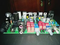
Good job! Have u powered it up and done any critical listening yet? I have an ODA and have been using out for many months daily.
I hope you enjoy yours as much as I do mine!
All the best
Alex
Good job! Have u powered it up and done any critical listening yet? I have an ODA and have been using out for many months daily.
I hope you enjoy yours as much as I do mine!
All the best
Alex
I've powered it up for a bit to test the voltages but have not listened to anything yet since I'm missing 2 heat sinks. I'm just going to wait for my back panel to come back from FPE.
I've powered it up for a bit to test the voltages but have not listened to anything yet since I'm missing 2 heat sinks. I'm just going to wait for my back panel to come back from FPE.
Hey good work on the board! I've sent you a PM. I mailed off two heat sinks today in case I forgot to include them with your package. Sorry about that if so! 😱
But the build instructions also may not be clear that you only need 2 heatsinks to do the testing, on the LM317 and LM337 pre-regulators, not on the LT1963A or the LT3015 LDO regulators. That is becuase most of the voltage drop is across the pre-regulators so they dissipate a lot of power. The LDOs only have a volt or so across them. In their case the rear panel heat sinking is more for long life down the road. Also if the ODA is used with anything near the full 400mA out per channel, in which case the LDOs would need the rear panel heat sink.
Let's get some sound going through it! 🙂
Last edited:
I just saw your post after replying to your PM! Thanks for the heatsinks. I owe you! I plan to build a second one and will use them for that build.Hey good work on the board! I've sent you a PM. I mailed off two heat sinks today in case I forgot to include them with your package. Sorry about that if so! 😱
But the build instructions also may not be clear that you only need 2 heatsinks to do the testing, on the LM317 and LM337 pre-regulators, not on the LT1963A or the LT3015 LDO regulators. That is becuase most of the voltage drop is across the pre-regulators so they dissipate a lot of power. The LDOs only have a volt or so across them. In their case the rear panel heat sinking is more for long life down the road. Also if the ODA is used with anything near the full 400mA out per channel, in which case the LDOs would need the rear panel heat sink.
Let's get some sound going through it! 🙂
Thanks for all your help and guidance! I can't wait to experience this amp with my tube dac and AKG 7xx!
I can't wait to experience this amp with my tube dac and AKG 7xx!
Congrats on your build!
I bought a pair of AKG K7XX a couple weeks ago (was able to grab one of the last 200 first editions 😀) and while I don't have a tube DAC, I can tell you they pair really well with the ODA. In fact they pair so well, I'm starting to think the ODA + K7XX > ODA + HE400 even though the Hifiman HE400 are more expensive headphones. It is really close... depends on what kind of music you're playing.
(And agdr is the best... can't tell you how many parts he's sent me)
Definitely post your first impressions!
So after a bit of troubleshooting, desoldering, resoldering and swapping components that were in the wrong place I put A/C jack to the AMP and switched it on to measure the voltages... They came out to what I expected... so I soldered in a jumper wire to power the rest of the board and all the lights came on!!
My first impressions...
WOW
I have not been able to listen to headphones in a few weeks due to my last amp biting the dust and so building agdr's ODA has been a very exciting project for me. I was able to find some old headphones I've long replaced for the AKG's and plugged them in for a test run. To my absolute surprise the low-end headphones SOUND AMAZING!!! My ears are in music euphoria just listening to the first thing I sampled. (Thirty seconds to Mars - City of Angels)
I'm still letting it warm up and break in but will fill you guys in with what I think in due time.
I still haven't received my front and back panels (FPE called me today - they're being machined today) but I can already tell that I will have one hell of a piece of equipment on my desk once this thing is all together.
Kudos to AGDR. Great experience building your ODA! and Thanks for all your help!
Hi all, I've been of the grid for a while and gaining speed slowly. I'll finish mine in a month or so and will report.
Regards
Regards
Where did you get the window?I simply used a hole saw with some cutting oil. It was very easy to drill and it made a perfect hole. I used a black permanent marker to colour the aluminum sides in black. The small window is glued from under with epoxy glue.
The hole diameter size is not perfect, maybe slightly too large but it was the closest hole saw that I had in stock.
The effort is definitely worth it! It's a dream to listen to.Hi all, I've been of the grid for a while and gaining speed slowly. I'll finish mine in a month or so and will report.
Regards
Hi all, I've been of the grid for a while and gaining speed slowly. I'll finish mine in a month or so and will report.
Regards
Hi Turbon! Yep time to fire up that soldering iron. 😀 Please let me know if any build questions come up.
DIY step-by-step photo build for a top slot ODAC board, part 1
I've finally had a chance to do a photo-build of the ODA top-slot carrier board for George's new ODAC rev B. 🙂 Here are the details.
In the photos below...
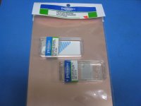
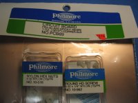
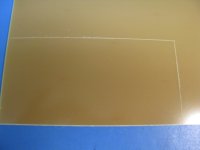
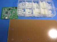
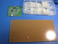
* The first two photos show the locally-sourced single sided copper clad board. Don't use double sided copper clad - any copper layer under the ODAC can short it out since it will mount down flat on the carrier board. The part under the ODAC is just the board with no copper. Don't buy the nylon bolts in the picture. I knew the holes in the ODAC were 3 mm dimeter. I couldn't remember when I bought this stuff if I had 3 mm nylon hardware (I did) and couldn't remember if 6-32 english is bigger or smaller than 3mm (it is bigger). So long story short - use 3 mm nylon bolts and nuts. 6-32 won't fit.
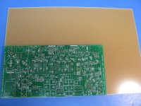
* The next two photos show using a bare ODA board to trace the 80x160 outline onto the clad board, using a sharp awl to trace around the ODA board. You can just draw a 80x160 rectagle directly, by meaurements.
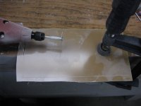
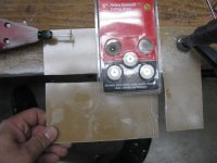
* The next three photos show cutting the board with a diamond cutting wheel on rotary hobby tool. The wheel and tool are from Harbor Freight here in the US - cheap, $5 for the cutting disks and $20 for the tool kit on sale. Note! Be sure to wear a dust respirator mask and safety glasses while doing the cutting. The board is fiberglass and epoxy resin, not the kind of dust you want to get in your lungs. The photos show that I first did a rough cut 1/4" or so past the scored outline, since the hobby tool shaft is only an inch long or so and can't reach all the way across the board. I re-clamped the board after the rough cut and was able to get the hobby tool in there closely for the final cut.
* The next two photos show the result. A perfect fit! 😀
I've finally had a chance to do a photo-build of the ODA top-slot carrier board for George's new ODAC rev B. 🙂 Here are the details.
In the photos below...
* The first two photos show the locally-sourced single sided copper clad board. Don't use double sided copper clad - any copper layer under the ODAC can short it out since it will mount down flat on the carrier board. The part under the ODAC is just the board with no copper. Don't buy the nylon bolts in the picture. I knew the holes in the ODAC were 3 mm dimeter. I couldn't remember when I bought this stuff if I had 3 mm nylon hardware (I did) and couldn't remember if 6-32 english is bigger or smaller than 3mm (it is bigger). So long story short - use 3 mm nylon bolts and nuts. 6-32 won't fit.
* The next two photos show using a bare ODA board to trace the 80x160 outline onto the clad board, using a sharp awl to trace around the ODA board. You can just draw a 80x160 rectagle directly, by meaurements.
* The next three photos show cutting the board with a diamond cutting wheel on rotary hobby tool. The wheel and tool are from Harbor Freight here in the US - cheap, $5 for the cutting disks and $20 for the tool kit on sale. Note! Be sure to wear a dust respirator mask and safety glasses while doing the cutting. The board is fiberglass and epoxy resin, not the kind of dust you want to get in your lungs. The photos show that I first did a rough cut 1/4" or so past the scored outline, since the hobby tool shaft is only an inch long or so and can't reach all the way across the board. I re-clamped the board after the rough cut and was able to get the hobby tool in there closely for the final cut.
* The next two photos show the result. A perfect fit! 😀
Attachments
-
 IMG_3334.JPG143.3 KB · Views: 346
 -
 IMG_3335.JPG171.7 KB · Views: 337
 -
 IMG_3336.JPG190 KB · Views: 337
 -
 IMG_3337.JPG115.1 KB · Views: 275
 -
 IMG_3340.JPG137.2 KB · Views: 130
 -
 IMG_3339.JPG154.1 KB · Views: 131
 -
 IMG_3338.JPG170.9 KB · Views: 279
 -
 IMG_3341.JPG158.4 KB · Views: 157
 -
 IMG_3342.JPG156.1 KB · Views: 149
Last edited:
DIY step-by-step photo build for a top slot ODAC board, part 2
In the photos below...
* The first two photos show placing the left edge of the ODAC rev B board exactly 5.0 mm from the left edge of the carrier board. Then scribe marks are made through the 3 ODAC monting holes. Finally the 3 holes are drilled. I first used a small 1 mm bit to help exactly center the holes in the middle of the scribed hole. Then I followed with the final 3 mm drill bit.
* The next four photos show using the 3 mm nylon bolts up from the bottom (the copper clad side) of the carrier board, through the ODAC board mounting holes, then securing with a 3 mm nylon nut. The final photo of the four shows that the resulting height of the nut and bolt extension is just perfect. Doesn't exceed the height of the USB jack on the ODAC board. The 3 mm nylon nut and bolt kit I'm using here is a common thing on eBay from many different vendors.
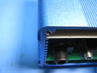
* The next 3 photos show the clearance of the tallest things on the ODAC board, the USB jack and a coil in the background, vs. the top of the ODA case. There is about 1 mm clearance, even if the top slot board is at the top of the slot. Note that I'm showing the front of the ODA here, but the ODAC and carrier board will actually turn around the other way and mount in the back
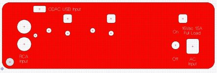
* The final photo is an image of the rear panel with the ODAC's USB jack hole added. The three existing vent holes have been moved down about 1 mm to stay fully under the top slot board. I'm sending one of these panels out to Front Panel Express on Monday. Once I confirm the hole is in the right spot I'll post the FPE CAD file for the rear panel with the USB jack hole out on the project's Google Drive link.
If you have an existing ODA rear panel and want to add the USB hole by hand drilling, here are some tips. The hole is 5.35 mm (0.21 inch) tall and 10 mm (0.39 inch) wide. Using two 3/16" drill holes side by side will get you pretty close. The remainder can be taken out with a nibbling tool or a file. The center of the USB hole as I have it right now (still needs to be confirmed by this panel I'm sending out) is 5.325 mm down from the top of the rear panel top, and 29.95 mm from the left panel edge.
In the photos below...
* The first two photos show placing the left edge of the ODAC rev B board exactly 5.0 mm from the left edge of the carrier board. Then scribe marks are made through the 3 ODAC monting holes. Finally the 3 holes are drilled. I first used a small 1 mm bit to help exactly center the holes in the middle of the scribed hole. Then I followed with the final 3 mm drill bit.
* The next four photos show using the 3 mm nylon bolts up from the bottom (the copper clad side) of the carrier board, through the ODAC board mounting holes, then securing with a 3 mm nylon nut. The final photo of the four shows that the resulting height of the nut and bolt extension is just perfect. Doesn't exceed the height of the USB jack on the ODAC board. The 3 mm nylon nut and bolt kit I'm using here is a common thing on eBay from many different vendors.
* The next 3 photos show the clearance of the tallest things on the ODAC board, the USB jack and a coil in the background, vs. the top of the ODA case. There is about 1 mm clearance, even if the top slot board is at the top of the slot. Note that I'm showing the front of the ODA here, but the ODAC and carrier board will actually turn around the other way and mount in the back
* The final photo is an image of the rear panel with the ODAC's USB jack hole added. The three existing vent holes have been moved down about 1 mm to stay fully under the top slot board. I'm sending one of these panels out to Front Panel Express on Monday. Once I confirm the hole is in the right spot I'll post the FPE CAD file for the rear panel with the USB jack hole out on the project's Google Drive link.
If you have an existing ODA rear panel and want to add the USB hole by hand drilling, here are some tips. The hole is 5.35 mm (0.21 inch) tall and 10 mm (0.39 inch) wide. Using two 3/16" drill holes side by side will get you pretty close. The remainder can be taken out with a nibbling tool or a file. The center of the USB hole as I have it right now (still needs to be confirmed by this panel I'm sending out) is 5.325 mm down from the top of the rear panel top, and 29.95 mm from the left panel edge.
Attachments
-
 IMG_3343.JPG171.4 KB · Views: 133
 -
 IMG_3344.JPG151.6 KB · Views: 113
 -
 IMG_3348.JPG122.3 KB · Views: 134
 -
 IMG_3347.JPG213.6 KB · Views: 139
 -
 IMG_3346.JPG190.6 KB · Views: 108
 -
 IMG_3345.JPG143.6 KB · Views: 110
 -
 IMG_3349.JPG166.1 KB · Views: 128
 -
 IMG_3351.JPG166 KB · Views: 128
 -
 IMG_3352.JPG187.5 KB · Views: 135
 -
 Rear panel with ODAC usb.JPG169 KB · Views: 119
Last edited:
Thanks, Alex! 🙂
I forgot to post that those 3mm diameter nylon bolts are 6mm long, which is the length of the threaded portion.
I forgot to post that those 3mm diameter nylon bolts are 6mm long, which is the length of the threaded portion.
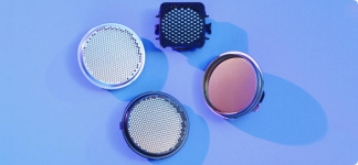
I got the window from disguarded ultrasonic Kodak range sensor. They are used on snow height sensors, and we replace a bunch of these sensor every year at work. I just go through the garbage can 😉
Attachments
Last edited:
New BOM posted with +/-15Vdc rail build option changes & input jack pix
I've recently had opportunity to build up a +/-15Vdc version of the ODA for use with some 600 ohm headphones. In the process I discovered a couple of changes/additions needed in the BOM related to using the +/-15Vdc rails. The revised ODA BOM is included below as a zip, and I also have it posted out at the project Google Drive link in the first post in this thread.
Here is what has changed, since the previous 3/20/2015 BOM I've had posted:
* I had forgotten to include the value of the relay circuit voltage rgulator set resistor, R70, used with +/-15Vdc rails.
* The two optional bass boost resistors (for any rail voltage) were incorrectly listed as R24 & R25, when they should have been R22 & R23. This was never noticed since so few people have used bass boost. Lately I've been suggesting to folks building the ODA they use an external equalizer instead. The circuit on the board is pretty limited with just one breakpoint. With an equalizer you can set your boost frequency and and amplitude to anything. If I ever do another version of the ODA I'm going to leave bass boost parts off entirely.
* The R24 & R25 gain stage feedback resistors are now specified as a 0.1% through-hole part, rather than 1% previously. Just occured to me that would be an easy and effective change, since all the gain set resistors are already 0.1% surface mount parts. These pads for these two resistors are already set for use with the longer (than 1/8W) 6.2mm body size, since I had higher power specified to lower thermal rise and hence Johnson noise. Turns out Digikey has the perfect part that fits, as specified in the BOM, and it also isn't much more in price than the previous 1% part. Mouser has one, but it is in a longer 7mm body size that would work, but would have to be angled slightly to fit the board pads. The Mouser part is also double the cost. The net result here is just obtaining as close a channel-to-channel gain match as possible.
* A note has been added with R31 and R32, the attenuation resistors, that they are not used at all (jumpered across) with the +/-15Vdc power rail build since the assumption with +/-15Vdc is you needed more voltage swing in the first place. The attenuation resistors cut the maximum output swing voltage in half if used.
* I had forgotten to add a note that two resistors in each channel's DC offset null circuit have to be changed for use with +/-15Vdc power rails. The reason is the NJM4556AL chip's inherent DC offset rises from the 3mV typical with +/-12Vdc rails to around 6mV. The resistor change, from 5.49K to 1K,, gives the DC null trimpots -12mV full scale adjustment range, which is around -6mV in the middle. Note that two of these are surface mount, R47 & R48, while the other two are through-hole, R54 & R58.
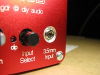
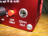
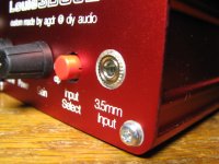
FRONT PANEL INPUT JACK THREADS
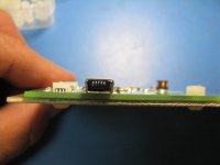
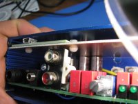
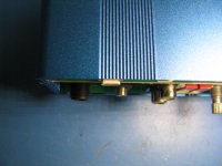
In other ODA news I've had a couple of people building ODAs PM me over the last few months about the input 3.5mm jack threads not extending far enough through the front panel. On this most recent build I took some photos of the jack threads, below. The first two show the amount of thread extension through the front panel, about 3 threads as I intended by design, and then the second two photos the result with the nut screwed on. I haven't done anything special here, just built it up and this is the result.
I've been a little puzzled why folks haven't had their threads extend enough through the hole, since everytime I've built one it worked just fine, as in these photos. A possbile reason finally hit me though with this last build. You have to have both your front and back panels fully screwed onto the case first, before trying to put on the front panel input jack nut. The tolerances involved are fairly small, just three threads, and I noticed that until I actually screwed both panels down the threads didn't extend through the front panel hole enough. the spacing around that 3.5mm jack nut is also fairly small.
I use my Xcellite 378M pliers that have fine nose tip to secure that nut.
Lol - in reviewing these pictures just now here is another useful thing here. Note the button color changed between pictures. 🙂 Turns out that in addition to black (PVBK) they also make a red button, "PVRD", a white button "PVWH", and a grey button "PVGY". No blue though. 🙁 Mouser only has black and red, but digikey has all the colors.
I've recently had opportunity to build up a +/-15Vdc version of the ODA for use with some 600 ohm headphones. In the process I discovered a couple of changes/additions needed in the BOM related to using the +/-15Vdc rails. The revised ODA BOM is included below as a zip, and I also have it posted out at the project Google Drive link in the first post in this thread.
Here is what has changed, since the previous 3/20/2015 BOM I've had posted:
* I had forgotten to include the value of the relay circuit voltage rgulator set resistor, R70, used with +/-15Vdc rails.
* The two optional bass boost resistors (for any rail voltage) were incorrectly listed as R24 & R25, when they should have been R22 & R23. This was never noticed since so few people have used bass boost. Lately I've been suggesting to folks building the ODA they use an external equalizer instead. The circuit on the board is pretty limited with just one breakpoint. With an equalizer you can set your boost frequency and and amplitude to anything. If I ever do another version of the ODA I'm going to leave bass boost parts off entirely.
* The R24 & R25 gain stage feedback resistors are now specified as a 0.1% through-hole part, rather than 1% previously. Just occured to me that would be an easy and effective change, since all the gain set resistors are already 0.1% surface mount parts. These pads for these two resistors are already set for use with the longer (than 1/8W) 6.2mm body size, since I had higher power specified to lower thermal rise and hence Johnson noise. Turns out Digikey has the perfect part that fits, as specified in the BOM, and it also isn't much more in price than the previous 1% part. Mouser has one, but it is in a longer 7mm body size that would work, but would have to be angled slightly to fit the board pads. The Mouser part is also double the cost. The net result here is just obtaining as close a channel-to-channel gain match as possible.
* A note has been added with R31 and R32, the attenuation resistors, that they are not used at all (jumpered across) with the +/-15Vdc power rail build since the assumption with +/-15Vdc is you needed more voltage swing in the first place. The attenuation resistors cut the maximum output swing voltage in half if used.
* I had forgotten to add a note that two resistors in each channel's DC offset null circuit have to be changed for use with +/-15Vdc power rails. The reason is the NJM4556AL chip's inherent DC offset rises from the 3mV typical with +/-12Vdc rails to around 6mV. The resistor change, from 5.49K to 1K,, gives the DC null trimpots -12mV full scale adjustment range, which is around -6mV in the middle. Note that two of these are surface mount, R47 & R48, while the other two are through-hole, R54 & R58.
FRONT PANEL INPUT JACK THREADS
In other ODA news I've had a couple of people building ODAs PM me over the last few months about the input 3.5mm jack threads not extending far enough through the front panel. On this most recent build I took some photos of the jack threads, below. The first two show the amount of thread extension through the front panel, about 3 threads as I intended by design, and then the second two photos the result with the nut screwed on. I haven't done anything special here, just built it up and this is the result.
I've been a little puzzled why folks haven't had their threads extend enough through the hole, since everytime I've built one it worked just fine, as in these photos. A possbile reason finally hit me though with this last build. You have to have both your front and back panels fully screwed onto the case first, before trying to put on the front panel input jack nut. The tolerances involved are fairly small, just three threads, and I noticed that until I actually screwed both panels down the threads didn't extend through the front panel hole enough. the spacing around that 3.5mm jack nut is also fairly small.
I use my Xcellite 378M pliers that have fine nose tip to secure that nut.
Lol - in reviewing these pictures just now here is another useful thing here. Note the button color changed between pictures. 🙂 Turns out that in addition to black (PVBK) they also make a red button, "PVRD", a white button "PVWH", and a grey button "PVGY". No blue though. 🙁 Mouser only has black and red, but digikey has all the colors.
Attachments

Last edited:
- Home
- Amplifiers
- Headphone Systems
- A version of an O2 Desktop Amp (ODA)