Help 1 channel dead, AC in chassis.

I am at my wits end and its eating me. So I built a new version of my old amp, fancier chassis, better OPTs. And its working great. But I took the old amp (that has been working flawlessly for five years) in to my workspace and thought I wanted to play a little with it. Tube rolling for one. Put some 6n6p in place of e88cc AND somewhere along the way - moving from the living room to my working room (not calling it a workshop, cause it isnt) and putting new tubes in it something has happened. Only one channel is playing. Playing fine, no hum, no hiss and the other channel is just dead. Tubes light up fine on both sides. Anyway, its not that I need the amp anymore but I figured it could be some training to get it running so I have changed the entire PCB (I have several) newly populated, only thing I had to move from the old one was the coupling capacitors. Same thing. Changed the input RCAs. Changed to another set of OPTs. Changed back to the old ones. Same, same, same. One channel is dead AND I have 80v AC in/on? the chassis and I can not see where that is coming from. I just cant understand. Anybody get any ideas what I should check. BTW I do not have any fancy instruments. Only a universal meter.

Can a helmholtz resonator be used for soundproofing a room?

This is a specific question. My workplace is located in a poorly constructed building and there's an office above me, where people occasionally stomp. The worst part is heeled shoe women loudly stomping on some parts of their floor (my ceiling), where the entire room just booms loud. There's also the annoying heel loud click, but it is not so severe and can be drowned with music.

I could not manage to get along with these assholed people, so my only option is to move or somehow kill that bass resonance. It seems to be at a specific frequency, so I wondered if a Helmholtz resonator tuned at that specific frequency might help absorbing this frequency peak?

Advice needed for driver selection

Hi everybody, planning a 3 way bookself. I dont want earth shattering bass, so no subwoofer. My plan is to use a 5 inch woofer, 3 inch full range, as i already own it, and 3/4 inch tweeter driven by 2nd order crossover and tpa 3118 class D amp.

Earlier thought of a single driver system, so TC8FD05-04 - 3" Paper Cone Full Range is purchased. Now, i am going to purchase SB Accoustics SB13PFCR25-4 5'' Paper Cone Woofer and Dayton Audio - TD20F-4 - 3/4" Soft Dome Neodymium Tweeter 4 Ohm.

Are they ok for my project? Or i should go for Dayton Audio - ND140- 4 - 5-1/4" Aluminum Cone Midbass Driver 4 Ohm? How about Peerless Fabrikkerne (I) Ltd - TL25AN - Aluminum Dome Tweeter?

Tight on budget, so not considering higher priced tweeters. Peerless Fabrikkerne is Indian brand and read they are not upto standard, not sure though, but goes upto 1.5khz.

Preferring sealed enclosure as small as possible. So dedicating woofer to its duty and FR for high bass and mid. Thats why 3 way is considered. Am i wrong? Thanks in advance.

Attachments

Sanwu TDA7492 and volume potentiometer

Hello everybody

After a long time of research, I would like to solicitthe diyaudio community for this question.

I would like to add a volume log potentiometer to my Sanwu TDA7492 + CSR8635 bluetooth board (please find attached a picture of my board).

Indeed, I want to add a volume potentiometer before the TDA7492 amplifier in order to change the volume, no matter the source (in my DIY project, the board is connecting permanently to the aux input and the bluetooth input, and the source is chosen by a manual switch).

I would like to know if it is possible, and where can I add a volume potentiometer to control the volume.

Thank you in advance for your help.

Note : For my project, I work in Mono. I flashed the CSR8635 Bluetooth module to work in Mono only. So I guess I will only use the L channel at the end. So I want to know how to wire a single potentiometer of 22k resistor.

An externally hosted image should be here but it was not working when we last tested it.


tda7492_circuit_diagram_pinout_pin_connections_2_16c.jpg

Allen Model 75 mon block tube amps

Moving back to the midwest so I'm putting my Allens up for sale. They are working flawlessly but I don't want to try to ship them back to Iowa. I have until the 20th of May to sell these or try to find room on the motor home which is already crowded.

Price for the pair at $1100.00 cash and you pick up here in Casa Grande, AZ

PM me for my phone number if interested. No trades and my price if firm.

BUZ71 equivelent?

Hi, got an amp with BUZ71 mosfets I want to change out from the power supply as some are reading faulty, is there a newer equivalent I can put in and would I need to change gate resistors to suit? the amp is nothing special but interests me so would like to fix it up, it's a Precision Audio "Hot Shots", which is a bit of a joke amp but would like to see it work again!

Mark.

Martin Logan Depth i subwoofer amp board KABOOM!!

Hi everyone, I am new to the forum.

:cop: Moderation note

Technical question below moved here:

Martin Logan Depth i subwoofer amp board KABOOM!!

Recently got a ML Depth-i Subwoofer for a project. After opening the sub for further trouble shooting, found out the amplifier board is totally fried! Corrosion on the board everywhere! After calling the ML service dept, I had the feeling that they are NOT going to do anything.....no parts, no suggestions..COVID-19 excuses.... So, I am thinking if it is possible to find an internal amp board that is compatible to the sub? I think the power supply is still good? I have no knowledge in circuit stuff and only know how to use the multimeter to check voltage and connectivity🙁😕 Correct me if I am wrong....power supply to amp board to crossover to sub cones? or is it possible to use an external amp to drive the sub? Thanks in advance for all the inputs and suggestions!!🙂

Markaudio CHN-110 bookshelf vs Classix II MT Bookshelf

Hello!

I am planning to build a pair of speakers as a gift to my friend for his birthday.

I have built 3 sets of speakers so far, CHR-70 3L sealed, 9L bass reflex and Fane SOVEREIGN 12-250TC 90L sealed.

I am considering smallest 18L Dr. Scott Lindgren design for the CHN-110.
F3 = 46Hz F6 = 39Hz. Paul Carmody says that Classix II has F3=34Hz.

Why am I comparing those two - price level is basically the same and the size is also similar 15L vs 18L. Both are quite easy to build.

My questions are:

1. Classix II has way more bass extension, but uses cheap drivers. Since I don't have experience with large bookshelf speakers I have no idea how different would these two speakers sound. Low and precise bass is always nice, but the mid-range magic and imaging that comes with MarkAudio full-range drivers is the main reason I got hooked in diy audio in the first place 🙂 Could someone with more experience please describe the differences in more detail between those two designs.

2. CHN-110 is rated at 45W nominal and Classix II is rated at 60W. What would be the best bang for the buck amplifier solution? It's either TDA7498 or TPA3116 based Bluetooth amplifiers (both cost around 40 EUR), but the most powerful power supply that is cheap (max 15 EUR) is 24V 5A. Anything with higher ratings - then price jumps considerably (TDA7498 can take 36V). What I've managed to find with google, is that 24V 5A power supply gives me around 38W at 8ohm with TPA3116 based amplifiers. Are any other boards that sound great, cost about the same and give out more power with 24V 5A power supply? Or is this power supply my limit - 38W at 8 ohm and it doesn't matter what board I use?

Thank you for all the help!

looking for inspiration: Music Database

Hi friends

Oftentimes, I just can't solder around.

So I started to build a database (ninox) where I try to gather and connect as much information as possible as fine-grained as possible, like

  • who wrote (what piece)
  • who played (what instrument)
  • who contributed (on which track)
  • who recorded it
  • who published it
  • what do I or other family member like
You get the picture. Kind of a clone of discogs, merged with my iTunes-library or something like that, so that I can dig out specific informations from the collection...

Of course, this task barely has a boundary, and so I'm quite overwhelmed of its complexity. I would like to find solutions on both the technical (database-design) level as well as the logical level (where to best hook attributes like "authorship, contribution, role" etc.)...

Is there a place where such issues are discussed?
Could this be the place?

Thank you, enjoy sunday!
david

(context:
I listen to music more than not, and try to build knowledge about it.

trying to set up a sort of a catalogue of my music-library, which consists of a inherited collection of classical records (~1500 vinyls), and there's some records in the world of pop/jazz/etc. (~300 vinyls). Plus a huge collection of digital files (~500 ripped CD's, + ~300 Albums purchased through bleep + bandcamp)
)

Problems with L25D DIY AMPS

I decided to make my amps myself rather than buying brand new ones.
I left on a base of L25D (IRS2092 + IRFB4020PBF) from JLM.
The set will be powered by + - 75V by a custom toroidal transformer , a power supply card and protection HPs.

An externally hosted image should be here but it was not working when we last tested it.


After modeling to choose the case:
An externally hosted image should be here but it was not working when we last tested it.


I started manufacturing:
An externally hosted image should be here but it was not working when we last tested it.


An externally hosted image should be here but it was not working when we last tested it.


An externally hosted image should be here but it was not working when we last tested it.

Should I measure my speakers?

I’d like to know your opinion. By the time making the speaker, shall I use manufacturer’s provided information or measure it by myself? The information such as frequency response, impedance curve, inductance, etc. I think that the data from manufacturer probably are more correct than self-measuring because they may use the more precise equipments and methods in measurement. However, as someone says that since it was a commercial, the spec might be fabricated to have more beauty, and probably just a sample from a lot. So I thought would it be better to measure with our moderate precision equipments and method ourselves. But that also the question for the purpose of spec from manufacturer. Thanks in advance

ARCAM A75 help

I recently picked up a used ARCAM DiVA A75 integrated (50WPC) for a song because it had a problem. Seller stated the amp would not go out of protection mode on turn on, relay would just keep clicking. I contacted ARCAM about this and to my surprise got a response same day. Probable cause according to ARCAM was cold solder joints on the output transistors. Sure enough that was the problem. I re-soldered them and that particular problem was solved.

Which brings me to the purpose of this post. Right off the bat this amp sounds like s**t...boring, lifeless and veiled. I've owned several ARCAM integrateds including the Alpha 9, which I'm currently using, the Alpha 10, A65+ and the A70. Everyone's aural memory is short but I do remember the A65+ (40WPC) sounding better than the A75. To my ears the Alpha 9 is the best sounding of the lot and the A75 the worst. ARCAM also made a A75+ which I haven't heard. I contacted ARCAM three times asking what the difference between the A75 and the A75+ was to no avail. Does anyone have any idea what the difference is? They obviously tweaked the plus version cause the other sounded like crap.

For those of you who don't know the Alpha and Delta series of amps used MOSFET outputs and the DiVA range, which followed the Alpha's, use bi-polar outputs. The A75 uses for the pre amp section one BurrBrown OPA2134 DIP op-amp and the phono stage uses one Philips NE5532 DIP op-amp. Are there any serious tweakers out there that can help to make this amp sound better?

Martin Logan Depth i subwoofer amp board KABOOM!!

Hi everyone, I am new to the forum. Recently got a ML Depth-i Subwoofer for a project. After opening the sub for further trouble shooting, found out the amplifier board is totally fried! Corrosion on the board everywhere! After calling the ML service dept, I had the feeling that they are NOT going to do anything.....no parts, no suggestions..COVID-19 excuses.... So, I am thinking if it is possible to find an internal amp board that is compatible to the sub? I think the power supply is still good? I have no knowledge in circuit stuff and only know how to use the multimeter to check voltage and connectivity🙁😕 Correct me if I am wrong....power supply to amp board to crossover to sub cones? or is it possible to use an external amp to drive the sub? Thanks in advance for all the inputs and suggestions!!🙂

DC offset problem outlaw 7125

Hi everyone,

I'm repairing an outlaw 7125. This amplifier is an AB class with only one potentiometer to adjust bias. Nothing to adjust dc offset.

Anyway i have 7v and 3v on 2 channel. Do you know what is causing this ? I'm comparing a working and a bad channel and i found nothing. Already replace all capacitors. Test every transistors and resistors. I'm not able to find the source of this issue.

I tried to have the schematic or service manual but it's not available anywhere. I wrote to company and not providing any schematic.

So i did it. But again i dont find the problem. I will need help on this one.

I read somewhere that some model without dc offset adjustment, transistor need to be matched. Is it possible ti have good transistor but not matching anymore ?


This is my schematic:
Microsoft OneDrive - Access files anywhere. Create docs with free Office Online.

Thank you for your help.

How does this DC offset setting VR work?

I am working on a Technics SU-50A. The Right channel can be perfectly set to 25mV of bias and close to 0mV of DC offset. The Left channel's DC offset is about 155mV when RV17 is turned all the way. It's bias is ok. I have checked the differential pairs, TR17/19 and TR21/23. They seem to match well.

Can someone educate me how dialing RV17 can affect the DC offset? What should I do to bring the DC offset down?

Attachments

  • main amp.jpg
    main amp.jpg
    155.1 KB · Views: 196

LG g3 to projector

Hello guys, at some time i started to think about getting a projector but they are very expensive , and cheap ones are very bad. i am thinking now that i wont loose much by making projector myself instead of buying cheap one.
Sad that I discovered this forum after I ordered all parts
so i have lg g3 phone ips screen with 1440 x 2560 pixels resolution 5,5 inch in size i am going to put it in between these lenses High Quality 1 Pair DIY Universal 7 Inch Fresnel Lens 0.1mm Spacing For HD Projector FPV Goggles Headset-in Parts & Accessories from Toys & Hobbies on Aliexpress.com | Alibaba Group and problem is i have no idea how to choose lens for image projection , in front fresnel lens is 170 mm for focus so my current choice is lens witch claims to be 180 mm focal length
Factory sale! LED Projector DIY Lens Focal Length f=180mm DQPL F180 Projection Lens for 3 7 inches Projectors LCD-in Projector Accessories from Consumer Electronics on Aliexpress.com | Alibaba Group ? ,So my problem is i have no idea how projection lens parameters efects final image and want fresnel lens to fit the projection lense , maybe someone has any sugestions? I have space between projector and wall from 4-5 meters, is my 180 lens suitable for my setup or where is a better option?

At the moment I am waiting for parts to arrive
8.31.17
Fresnel lens and power supply has already arrived and i have found some coolers,
EmgIm9e.jpg

IRS2092 Failure Modes

Hello everyone,

I have come across some strange behaviour of the IRS2092 class D driver IC that I have not seen reported before. In the documentation the only damage warning that I can find relates to Vss falling lower than the COM (B-) supply:

VSS Negative Bias Clamping
An excessive negative Vss voltage with respect to
COM could damage the IRS2092(S). VSS can go
below COM when a negative supply is missing in a
dual supply configuration. To protect the IC from this
possibility, a diode is recommended for clamping
potential negative biases to VSS. A standard
recovery diode with a current rating of 1A such as
the 1N4002 is sufficient for this purpose.

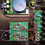
I have an ES1D diode in my design as per the above. My current project is based around the IRAUDAMP9 reference design, with the following changes:

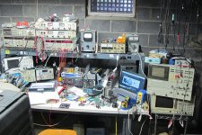
Gate resistors 10r instead of 4r7, reverse turn-off diodes across gate resistors, and separate power supplies for +/- 75V, Vaa, Vss, and Vcc (from individual transformer windings, rectifiers, and filter capacitors). Vcc is created with a 20V supply feeding a 7812 regulator, referenced to B-. I have reverse polarity protection diodes between B- and the VCC supply (at the input side of the 7812), B- to GND, and GND to B+. Each of the five power supplies has a protection fuse. The amplifier works perfectly with low noise and distortion, switching characteristics are all good, and I have no problems using it for the past few weeks. Yesterday I encountered something that I cannot explain: I was performing some measurements and accidentally powered up the amplifier without the fuse installed for the Vcc power supply. Obviously the amplifier did not start and there was no fanfare. I switched off the main power switch, waited for all the supplies to discharge, and then reinstalled the Vcc supply fuse. Bringing up the amplifier using a variac, the B+ and B- fuses quickly blew...they have never blown before. Upon inspecting the amplifier I found a ~200 ohm short between B- and system GND. I removed the IRS2092 IC and found the short was now gone. I double checked all of the surrounding components, including the BJT totem poles and the MOSFETS. Nothing else was found to be damaged, so I installed a new IRS2092, slowly brought up the amplifier, and it is again working perfectly. I decided to do an experiment to test the UVLO for Vcc and see if I could duplicate the failure...this is supposed to stop switching if Vcc falls below approximately 8V. I replaced the Vcc fuse with a high current switch, powered up the amplifier until it reached normal operation, switching present, etc., and then flipped the switch, disconnecting the 20V Vcc feed supply. Switching stopped immediately once Vcc reached just over 8V relative to B-. So far so good. I then switched off the main power switch, with the supply to the Vcc regulator still disconnected (simulating a blown Vcc supply fuse) and again the IRS2092 was damaged in exactly the same way. Replacing it got the amp working properly again. One thing to note is that on turn off the Vaa and Vss supplies (and Vcc, when it is connected) discharge much faster than B+/B-. Has anyone encountered this or any other failure conditions? Can anyone recommend what I might look at or implement to prevent this failure mode? I suppose I could just eliminate the fuse from the Vcc supply, but I like to have fusing when testing and measuring a new design...for obvious reasons.

Thanks!

2-Way Crossover Design

Hi All,

Hoping to get some feedback on the crossover for a project of mine. I am crossing over a SEAS 27TDFC H1189 to a TB W5-1685. I have developed a 2nd order high-pass/low-pass crossover (as I feel the drivers lend themselves well to 2nd order networks) with the high-pass at 2080Hz and the low-pass to the TB at 3360Hz.

I initially started with both being at 2300Hz but landed on these values after some tweaking on VituixCAD (I also added a 4ohm resistor to the SEAS and wired it in reversed phase to avoid a large trough in the frequency response).

Just hoping to have some feedback as this is a first for me. I also question my calculations for the low pass filter as the 3360Hz doesn't seem to correlate on the graph with the blue line for the TB W5-1685. Using equation 1/(2pi√(L*C)).

Graphs, circuit, and datasheets attached.

Thanks!

Attachments

How to calculate overload protection

Hi,

I want to add a current overload protection to a regulated high voltage power supply.

The design is somewhat similar to the schematic attached (but with zener stabilization), using a power MOSFET. The default output voltage is 600 VDC. The default current will be around 400 mA (fixed current, true class A amplifier).

How should I calculate the resistor value for the BC337 to get a current protection for 450 mA or 500 mA?

Regards, Gerrit

Attachments

  • AA45CC34-319B-4A14-90C2-FE1E2C42FAAA.png
    AA45CC34-319B-4A14-90C2-FE1E2C42FAAA.png
    86.1 KB · Views: 121

IEC Power Connector

It is always convenient to design a new build around an IEC standard power adaptor, and generally people opt for the C13/C14 type, which is similar to (but not the same as) a 'kettle cord'.

There is another polarised type with earth connector, the C5/C6, aka 'Cloverleaf' or 'Mickey Mouse' connector. It is rated to 2.5A, 7A in the US, so should be meaty enough for any amp with a 300VA power transformer, with plenty of margin for safety.

I'd like to retrofit some Quad II's with earthed power leads, and there is just insufficient room in the old voltage selector window for the C13/C14 type. Rather than hack the old chassis, I could fit a C5/C6 type with no surgery required.

To be on the safe side, I was wondering if there is there any safety reason not to do this?

Attachments

  • C5 C6.png
    C5 C6.png
    9.5 KB · Views: 592
  • C13 C14.png
    C13 C14.png
    5.9 KB · Views: 603

Insulation thickness for p2p wiring

I'm searching Farnell for 22AWG stranded wire used for heaters and also some other connections in line level stages. Typical requirement is 6V/600mA, never had problems with wires similar to Tasker C111.
Shops are closed so i have to order something without seeing and touching it, the problem is i spent 2 hours trying to calculate or find diameter of 1 external core from multicore cable. It is pretty clear here, 1,8mm dia for 22AWG core.
https://www.tme.eu/Document/e9b173cef568e662b651ce08f5ffc9af/TAS-C106.pdf
Online shop where i want to buy this wire also carry some other things, if i make sure wire is how i need it i can avoid 2 shippings. Datasheet shows 0,76mm conductor dia and 1,27mm insulation diameter:
http://www.farnell.com/datasheets/1...2Yb963grkGG4pRW2sij6WKAS5e0y6CchoCOtIQAvD_BwE

Do i just calculate 1,27+0,76 =2,01mm to get diameter of 1 core with insulation, or am i wrong about it?

What's a safe excursion limit (relative to Xmax)?

I'm planning a voice coil for a 12'' subwoofer I'm going to build, and I already have the magnet and the frame.

I made a test coil to measure the force factor, and from measuring it's dimensions (plus assuming it uses some common materials) I created this model in FEMM:


YTckWkZ.png


From using those materials the force factor fitted right away.

You can see I've already added a voice coil to the model.

My doubt is the following: I planned the coil to be 27 mm tall so it could have a 10 mm Xmax. But, like that, when being fully "down" (like in the picture), the bottom of the coil itself would be 6 mm from the bottom (from hitting that curved part of the bottom).

Considering that I need a bit of former left below the coil (to avoid it from bottomming out when going "up"), this leaves me with very little window to anything. It could easily hit the bottom when going down.

So what you think is the wiser to do?

What you think it's a safe Xmax to avoid the chance of mechanical damage?

Note I'm planning to use this sub in a transmission line enclosure, and I'm planning to use it with a 150 W RMS class D amplifier. I'm not yet sure of how much excursion I'm going to need and how much control the enclosure will offer, but I'm following the parameters of known 12'' subs of similar power rating.

Hypothesis - improving off-axis dispersion from a dome tweeter

So we know that with diaphragms undergoing pistonic movement, the radiation pattern transitions from spherical/hemispherical to something that looks more like a beam as the frequency increases. The reason for this is because as the wavelength shortens, the sound waves produced at different areas of the diaphragm start to destructively interfere (combine out of phase) at the listening/measuring point, instead of constructively as they would at longer wavelengths.

What if we reduced or blocked the output from one part of the piston (in this case a dome tweeter) so that only a smaller portion would radiate to the point of interest? In theory, this would increase the frequency at which the dome would start to beam. One way to do this would be to put a thick sheet of felt over the dome, almost in contact with it, but with a small circular hole right over the tip of the dome. The portion of the dome visible through the hole would radiate as normal, as long as the listening/measuring angle was not occluded by the periphery of the hole, but all the other parts of the dome would not be able to contribute their sound energy.

So, this should work to improve off-axis response at high frequencies, but we've done nothing but turn one dome tweeter into a smaller dome tweeter, which is hardly better than selecting a smaller dome tweeter to begin with. The major downside we have now, though, is that the surface area has been significantly reduced which in turn reduces the peak displacement of the dome. This means that we now have less clean output at the low end of the dome's passband. How to get around this? Use a thinner sheet of felt, so that low frequencies (which constructively interfere) are less attenuated, while high frequencies (which generally interfere destructively) are more attenuated. One can imagine that there is a sweet spot, or sweet "range" of thicknesses that may be suitable for this application.

The end result is a dome tweeter that has perhaps a negligible drop in sensitivity at the low end of the passband, a slight drop in sensitivity in the midrange, and a significant drop in sensitivity at the top end of the passband, but with a significantly improved off-axis dispersion at the top. Easily solved with EQ, and the nice thing is, the tweeter is unlikely to thermally overload under normal SPLs since the spectral distribution of energy in almost all kinds of music drops with increasing frequency above 300-500 Hz. Off-axis dispersion is more important in near- and mid-field listening, which comparatively requires less power as well. Excursion is a moot point since the the whole point is to select a felt thickness that hardly attenuates the frequencies where dome displacement is critical.

Unfortunately, all of the above is purely my conjecture... I would love for anyone to put this to the test. I'll even pay for the felt!

DAC output stage with gain - good devices/circuits?

First off I have to say that all my knowledge base is in building tube gear, and my solid state knowledge is pretty basic.

I need a gain of about x2 or x3 between the output of my AK4490 DAC with NE5532 output, and my 300b SE two stage amp. Obviously I want the cleanest most transparent solution possible and I'm open to a solid state device, rather than a transformer.

I have no knowledge how to implement this, so I'd be extremely grateful if you could point me in the direction of what I need. I can build circuits and PSUs, though I haven't worked with SMDs. Thank you in advance.

what could possibly go wrong, right?

So I just purchased a pair of Tang Band W8-1808 full range driver and started thinking about what I could do with them.

Currently I have a few pairs of unity / synergy horns (300-20k hz) together with some simple and plain open baffle bass speakers. Ofcourse not the best combo since the horns have a very high efficiency and the bass does not.

I like the open baffle / baffle less sound so I want to go all the way with that for this new project and because my new work space (which will also be the listening room) is way smaller than first, I want some smaller speakers.

I am really fond of speakers like the Kyron Audio Kronos or the ones from Reflector Audio.

I want to use my bass drivers that I already have since I like how they sound and perform, these are FaitalPRO 15pr-400. I made a design where both drivers are as close together as possible, thinking of a crossover around 120hz or so to give the full rangers some relief at the bottom end.

BUT now the BIG question, what will happen with this set up? I really dig the look and everything, but will the 15" movement closely behind the full range driver cause distortion? It is firing straight into it, ofcourse the full ranger will move approx. the same but has a cutoff where the FaitalPRO steps in.

Total disaster?? or will this be ok to try?

The frame connecting the two will be laser cut from 5mm stainless steel. As for the legs I have to figure out a nice way that is at a reasonable price...

Attachments

  • Screenshot 2020-04-26 at 18.34.48.jpg
    Screenshot 2020-04-26 at 18.34.48.jpg
    143.4 KB · Views: 271
  • Screenshot 2020-04-26 at 18.34.35.png
    Screenshot 2020-04-26 at 18.34.35.png
    621.8 KB · Views: 266

EKIO – Loudspeaker Management Application

EKIO is a Loudspeaker Management Application. It lets you customize the sound of your loudspeaker system so that it sounds and performs optimally. The app allows you to easily create a crossover for your full-range speakers. It lets you integrate a subwoofer and equalize your system.

It features:


  • Real time audio processing
  • Interactive EQ display
  • Crossover configuration
  • Parametric EQ
  • Driver alignment delays
  • Flexible routing
  • Drivers measurement import
  • Unlimited I/O
  • 64 bits processing, 44.1 to 192kHz
  • Optimized for low CPU usage and low latency
The FREE version is limited to two inputs and four outputs.

We publish today EKIO v1.0.3 which contains a few bug fixes.

To learn more about EKIO, visit our website : www.lupisoft.com/ekio

Regards,
Lupisoft

A little help evaluating price/value of two Sowter transformers

I'm in the process now of fabricating a project that uses transformer coupling at the input, 600 to 10K line transformer. I would like to get Sowters but for the two models I'm looking at the price nearly doubles one vs the other. The project I'm doing is on another post here, basically a computer desk amp where I might have 6-8 different sources plugged in at once sharing the ground. So I want a transformer input to alleviate ground loops and get some gain.

Can someone more familiar with input transformers tell me what I am getting for the extra money between these two models? I understand that quality vs price is never linear, but I have no problem spending for the more expensive model if the sonic reward is measurably greater.

USD $74

https://www.sowter.co.uk/pdf/8540.pdf

vs...

USD $138

SOWTER TYPE 3575 TRANSFORMER

Here are some of the advantages I've garnered so far for spending more on the 9063 model:

1) I can have a balanced input source as well as all my RCA sources.
2) More headroom and inductance, all the sources will be from op-amps (CD, DAC, Random headphone output of a phone, Bluetooth adapter, my DJ fader, etc). Some sources may be "hotter" than others.
3) More bandwidth
4) Better distortion
5) Having separate secondaries offers more parallel/series design choices for wiring it up.

What do you think? Should I spring for the $138 model? We only live once.

Greetings from Chicagoland

Hi All,
We've been cooped up in our house here for weeks due to the covid-19 thing so I figured it was time to do something about some old speaker cabinets I have. After doing some initial internet research, I've come to the conclusion that the only way I'm going to get satisfactory results is with a little help before I jump in.

Please take pity on this noob and thanks in advance for any direction you can provide.

Wayne’s BA 2018 Line Stage impressions

At last! I tamed the beast! After a lot of effort, troubleshooting and back and forth got it to work. It turns out that the main issue, I believe, was that I had not installed R23 and C4 in the circuit, which apparently that option is for the big output transistors. Maybe cleaning all the flux, going over a few suspect connections and rewiring everything, had an effect also. With my FW F4, it was working perfectly right nevertheless without any anomalies whatsoever. There is a big 220uf cap in its input circuit, so I guess it has to do with it working.

With my Pass XA25 it turns out that it was responding in its protection mode. This is apparent because it responds with very low gain and does not get hot. It turns out that after installing R23 and C4 the offset output had gone up to almost 1v. Dialed these down to “0” v and everything was ok.

The LS even without break-in sounds very refined, smooth, transparent as hell, soundstage is huge and all the instruments are very palpable. Gain is a little less than with the ba-3, where my attenuator position was usually at the 9-10 o’clock now it is at 11-12. Even with the F4 its position for equivalent output volume is at the 2-3 o'clock position.

But the big surprise was its synergy with the F4. If you want to know how this linestage really sings you have to listen to it thru the First Watt F4. It is really that good, both are that good, a revelation. There is an effortlessness quality that is very special and musical. It does not have the punch and dynamics of the XA but its presentation is kind of delicate or I could say ethereal. I hope that the tribulations addressed above help future builders. Thanks to Wayne for this outstanding design, and I wonder how it would compare with a PL XP-12.

super tweeter for jbl 2425h

hi everybody,
i do some FR test on my 2425h (with horn) and i found that it fall about 5KHz.(see pic)
the measure taken from listening position (not 1m from the horn)
i looking for super tweeter for about 80$.
i buy the fostex ft17, but it start to rise from 5KHz, so its not fit.
i interesting in something like jbl 2405 (but chip). the directivity issue interesting me.
i found the Selenium St320, but only one pice.
Beyma CP21 is little expensive.
Would appreciate help in finding tweeter that suits me.
thanks

Attachments

  • Untitled.jpg
    Untitled.jpg
    177.1 KB · Views: 227

Input Selector and Digital Volume Control

Hello everybody
I have an idea like this.

By giving a single button pulse with a cmos ring counter (cd4017). Do I have problems if I make the input selector by applying a relay with the transistor at the output?

If I combine the sample schemes for the counter and the relay stage, if I do this with double contact relays and use the chassis of all inputs, does the loop, etc., do any of those have done before?


As the third stage, how do you think if I combine a digital volume control integrated with the volume of 2 buttons and mute and gather on a single board?

Attachments

  • 20200428_032544.jpg
    20200428_032544.jpg
    548.2 KB · Views: 394
  • 20200428_031907.jpg
    20200428_031907.jpg
    219.6 KB · Views: 376
  • SLC.PNG
    SLC.PNG
    86.6 KB · Views: 618

a different active crossover design

Hello everyone,


I have found this paper by TI http://www.tij.co.jp/jp/lit/an/slyt299/slyt299.pdf and designed an active crossover in this way.
It gives a linear phase response and avoids coupling capacitors. I prefer DC coupled designs and avoid coupling capacitors whenever I can. For compensating the low frequency loss in open baffle or dipole speakers I have added a low freq. boost. It can also be useful with closed subwoofers.
I use 2 of these crossovers in my active speakers one for dipole bass F.A.S.T and the other one in my studio monitors and I'm very pleased by the results.

Attachments

Grounding speaker ground?

First the usual amateur, stupid question, etc. apology.
Then the question - and if there isn´t a fixed rule, if it´s topology dependent or otherwise, than this pertains push pull tube amps. So I´ve built two, el84 push pull triode strapped no feedback amps. And on both I have connected the speaker minus to the star grounding point which is then grounded to the chassis. And the amps has given me both pride and joy, so they are working well, but recently in a video somebody said that you connect the output transformer minus (black) only to the speaker jack, not to ground/chassis. And as I really don´t trust myself I have to check and double check. Looking at schematics, some are marked with the ground/earth symbol, and some are not.
What´s right and wrong here, and have I done something potentially dangerous? Thankful for input.

Line Stage For Aleph J (Glassware Specific)

Last year, I build my girlfriend a system. First was an Akitika GT-102 and pair of Klipsch RP600M using a Douk Audio Bluetooth tube pre-amp. Cost was a consideration, and she was just getting her feet wet. This seemed like a nice compromise.

There's a ton of brass and vocals in her favorite music. Think Herb Alpert and Billie Holiday. This combination was a little harsh sometimes. I wanted to soften it up, so I built a preamp using the Glassware Aikido 12vac.

Though there's a TON of gain, the little Aikido produced the effect I was hoping for. Reproduction is smooth and velvety. We both like her system quite a bit - especially at the price point.

Skip ahead... I was looking for a quarantine project, and I've been wanted to experience a Pass amp for a long time. I set out to build an F6, but ended up building an Aleph J because I can't currently source the F6 input transformers. The Aleph J is almost done. I need to sort out an issue with one of the channels.

The working channel is sounding pretty darn good! I think this is the best solid state amp I've ever heard. My main system uses an MC275 to Fried G3's. It's difficult for me to tell in mono, but I think there's depth between the instruments the Mac doesn't quite produce. I'll need much more stereo listening to develop my opinion; but - so far I'm very impressed.

I have another set of speakers in my work area. They're the same Klipsch RP600M's I bought for my better half. I typically drive them with a Tubelab SE 300B I built a few years ago. Except for the bottom end dropping off way too soon, it's enjoyable.

Testing with the Aleph J, the Klipsch's seemed a little shouty. Maybe it's an insult to use an amp of this caliber with $550 speakers... But, it got me thinking of the improvement that Aikido pre made in the other system.

Is anyone using any Glassware line stages with their Aleph J? I'd like to hear your experience. I'd also like to have a discussion about Glassware input buffers with the Aleph J (considering the pre I built had so much gain). Lastly, I'd like to know if anyone has experienced that 12vac kit as well as an Octal kit. I was wondering what differences they experienced.

I'd be happy to start another thread about the Glassware comparisons if this is too much in one place.

NwAvGuy O2 V11 PCB Group Order

Hi All,

I am planning on building the O2 Amp and will be ordering PCB's from JLCPCB in China. If I order 10 boards looks like the total cost with shipping will be around $ 30.00

If anyone wants these boards I can ship them to you and thus split the cost. I am guessing within the US shipping would be probably $4/board so maybe the rough cost would be $ 8.00/board (including priority mail shipping - I am leaving some room in case shipping turns out to be more etc). If all 9 boards are spoken for obviously the cost will probably go down even more...

Let me know if anyone else is interested.

(I am based in the US so will only ship to US addresses to keep shipping simple
Also payments would have to be via paypal to avoid any additional costs)

Help sought diagnosing LPSU issues

Hi, I am hoping for some help.
I am new to all of this.
I have started with a Pi and Ian Canada stuff. Fifopi, Transporter Pi and also a Khadas Tone Board (KTB)


I got a second hand Ian Canada LifePO4 LPSU.

I have had some trouble making it all work and assumed it was my inexperience, but have realised that the LPSU might not be right, so turned my attention to that.

The symptoms seemed to keep changing.
One of the things is that if I power the KTB from the 5v usb the music is crackly.
But if I power it from an old phone charger, it is fine.


I started off using the 3.3v rail J2 as it seemed to be a better source.
But it has deteriorated. It now jumps about and gives between 0 and 2.98v
Then the whole thing would shutdown almost straight away if I used it saying 'short protection'
However, in the manual it says:

In which conditions the power supply will turn off automatically
(1). If run time is up, the power supply will turn off automatically to prevent battery form possible over discharge.
(2). If any output voltage at J1 or J2 is lower than 3.3V, the power supply will turn off automatically to prevent
battery form over discharge.
(3). If there is short circuit to J1 or J2 output, or the output current is too high, the power supply will go back to
power off shortly after it was turned on.

So I assume it is down to it not giving 3.3v


Also, All but two cells give 3.65v when I test them in situ.
Apart from two. One gives 3.51v and another 2.98v


Oh, another thing. The 3.3v rail J1 gives 3.65v is that normal?
Shouldn't it be 3.3v?

Sorry it is so long, but I am not sure where to start.
Thanks.

Anyone have Teac X1000R repair experience?

My Teac X1000R reel to reel player has a problem with its right hand capstan/drive system. The capstan breaks a photogate when it falls signalling the motor controller to increase its speed. Unfortunately something is FUBAR and instead of providing smooth control it "jumps" too far up and them drops all the way down signalling the player to stop. I can get it running if i carefully spin the right reel but that is so frustrating...

I wonder if anyone has any experience with these players and maybe knows if it's a blown transistor somewhere. The other reel works great, and it sounds great, so I would love to get this thing working properly.

Can I get it professionally repaired this day and age?

Thanks a lot.

Tade

Chicago PHC-200A Hermetically Sealed Tube Power Transformer

For sale is a vintage Chicago PHC-200A high voltage plate and filament power transformer. It's a fairly rare hermetically sealed transformer and has been painted with several coats of hammertone paint. It now has a high gloss finish with swirls and patterns of superficial hammertone. It's ready to be mounted to a chassis and built into an amp.

It's used but in great shape, as you can see the leads will be easy to solder and are all intact. These units were popular for military applications and have a reputation for being very robust and quality transformers. Plus, I personally find the rounded corners and sides to be very aesthetic. I built a pair of mono-bloc 2A3 amplifiers with a smaller pair and was very pleased with both their looks and performance.

Here is some more information about the construction and the Mil-T-27 requirements involved in their design: http://www.bunkerofdoom.com/xfm/chicago1953/004.jpg

Here is the listing for the unit on the Bunker of doom website: http://www.bunkerofdoom.com/xfm/chicago1953/005.jpg

It is 450-0-450 volts at 200ma for the plate supply- 900VCT; 5 volts at 2 amps for the tube rectifier; a pair of 6.3 volt filament supplies at 4 amps; and a 6.3 volt supply at .6 amp. The unit weighs 12 lbs.

The dust on the unit is minor and exaggerated by the flash and will wipe right off (or not even be visible in normal viewing)

I had intended on building a 300B amp with it. But due to health reasons my amp building activities (all activities actually) have been drastically curtailed. So it's time to let someone else enjoy it.

Asking $60 plus shipping.

It will fit inside a USPS medium flat rate box and shipping will be $14.00 to the continental United States only (CONUS). The total will then be $74.00 shipped plus Paypal fees.

Thanks for looking at my ad!

Attachments

  • DSCF5221.JPG
    DSCF5221.JPG
    400.2 KB · Views: 165
  • DSCF5222.JPG
    DSCF5222.JPG
    415.8 KB · Views: 161
  • DSCF5223.JPG
    DSCF5223.JPG
    427.9 KB · Views: 152
  • DSCF5224.JPG
    DSCF5224.JPG
    444.7 KB · Views: 150

TA-377A Complementary Symmetrical FET Pre Amp

I recently aquired a TA-377A Pre amp.

For those not familiar with the pre amp it consists of a regulated power supply, a line stage and a phone stage. The line stage and phono stage are complementary and symmetrical FET designs.

It sounds like it could be very good and I am presently improving the capacitors to try and make it even better.

However I would like some information if anyone can help.

1) Does anyone know of any articles or threads on this pre amp. I have searched this forum and google but did not find any.

2) the fets are listed as 2n3268 (J40) and 2n3269 (K81). I can not find any specifications for those. Does anyone know these fets?

Any help appreciated.

Don

How to correct phase for IIR filters

Hello,

I have a Hypex Fusion plate amplifier that covers digital crossover and EQ duties. It can only apply IIR filters.

This works out well, as I wish to only use IIR filters as it avoids 'Pre -ringing' that occurs in FIR filters when you apply large amounts of EQ.

Here is an example of what pre-ringing sounds like:
This is the sound of 4 drum hits with no pre-ringing followed by 4 with pre-ringing. (I assume this is huge amounts of pre-ringing to make it so audiable)
ShortTest.flac - Google Drive

My application requires large amounts of EQ. (horn speaker).

I have set the crossover up, and EQed it. It sounds quite good.


For fun, I would next like to try and correct the phase of the speaker, to see what it does to the sound but without using FIR filters. (again due to the pre-ringing effect).

I appreciate that many will feel the phase will be in-audiable, but I would like to try anyway

I have read somewhere that this can be done by adding 'all pass' filters, which delays the signal so phase is correct. Can anyone link to or explain how this is done/calculated?

I can apply all pass filters in the Hypex fusion, or I can use any PC software you suggest.

Thanks!

TDA2050-Loss of details

Hi everybody,

This is my first post. Please consider me as an amateur with very basic knowledge about electronics and circuits.

After searching/reading this amazing forum for some time, I decided to start with TDA2050! And I built an stereo chip amp with two TDA2050. This is my first project.

I know that my chips are not authentic for sure (I used what was available). My caps do not seem to be authentic too. But anyway, I used what was available.

The power amp works just fine. No clipping, no distortion at all (dual 12V). The sound is good and powerful enough with my bookshelf Denon 6-Ohm speakers. The only point is that the sound is not as crystal clear as one expects!! The bass is fine but the high frequencies are missing.

I would be very thankful if you guys could help me improve the sound quality of my first project.

I have added both the schematic and a photo of the board. I should admit that the schematic is not mine, I just found it on the net and changed it a bit (decoupling caps).

Regards

Attachments

  • tda2050-1.jpg
    tda2050-1.jpg
    225.7 KB · Views: 509
  • tda2050-2.png
    tda2050-2.png
    407.7 KB · Views: 456

Build up Coral Beta10 closure

Hi all,

I'm going to build this BHL (attached). And there are few matter I dont know how to solve.
1. How to calculate dimension of each piece of MDF basing on this schematic? Or if you built it, could you provide me exactly what happened?

2. Polywood and MDF, what's the best choice in this case? 20mm or 25mm, what's better?

3. How about the hole 67mm rite on front side, it's to hang on a treble or it's a part of enclosure?

That's it!
Rgds,

Cominup

Attachments

  • backloaded horn 21.jpg
    backloaded horn 21.jpg
    60 KB · Views: 430

Filtering mains switching causing audible 'pops', etc.

I have an exceptionally simple linear power supply used by a stereo LM3886 based amplifier I built a few months ago. Occasionally, I hear moderately load pops on the speakers and telltale sounds giving the impression a neighbour is using an electric drill. I know there is a specific filter for this, but I want to avoid using a 'death capacitor'. The usual filter consists of a voltage-dependent-resistor, VDR, with a voltage/current characteristic similar to a stretched 'N'. Two other capacitors are used but they are grounded at one end and the other two remaining ends connect to the mains' N and L terminals.

Can I effectively use a somewhat inefficient filter with resistors instead of two capacitors with one of them connected like the dreaded 'death capacitor'? I am attaching the circuit. My questions is about resistors R1, R2 and U1.

Attachments

FS: 2 New NC400 modules

Still in original boxes. Also will include the following:

- (2) signal cables
- (1) power cable to match one SMPS600 to two NC400 modules
- (2) XLR jacks

Retail from Hypex, this would end up close to $800. I'll take $700 including shipping to you via priority mail. I take paypal and venmo. You take care of the paypal fees. Strongly prefer US buyer. You can pick up too if you're in the SF Bay area.

22963937262_f71b9a81f4.jpg

22977349085_0ee8d15331.jpg

bridged LM1875 >>ASYMMETRY<< issue

Built this circuit with 30-0-30 supply, driving a 17.5 ohm center tapped load. Scoped from center tap of the load to output of primary amplifier has very nice output, but the other inverted amplifier output is lacking resolution and decreased power. I do have some TL-072 chips that I could possibly employ to resolve the asymmetry issue, but would rather put those to use in a high power solid state amp. Any suggestions from knowledgable experts frequenting this forum shedding some light on what measures can be taken to resolve this issue are greatly appreciated.
Thanks, and happy DIYing! 🙂

Attachments

  • 044.jpg
    044.jpg
    981.2 KB · Views: 276
  • 048.jpg
    048.jpg
    978 KB · Views: 266
  • bridge2030.gif
    bridge2030.gif
    29.8 KB · Views: 291
  • 041.jpg
    041.jpg
    990.5 KB · Views: 290

SMP for Tube Preamp

Need help on Switch Mode Power Supply.
I have a general schematic but but its noisy. I know you can make them very quiet for tubes but i'm not sure how. I know it is going to have to do with frequency filtering.
Does anyone have any experience with SMPs and powering Tube preamps/amps?
Here is a schematic for a SMP running a preamp example. Ideally I would like to get this SMP to output 200v and have it quieter....I just am not sure how we get there.
An externally hosted image should be here but it was not working when we last tested it.

100 watt to 150 watt Class A integrated amp desig

good morning mates, its been very interesting and fun being here in this group, although i am not a well experienced audiotechnician since i was in industrial electronics in my job. I had experienced building design and DIY intergrated amps in my college days. I would like to ask you if you can just share your working complete design of a 100watt to 150 watt Class A integrated amp from PCB layout to discrete components list of parts or any Class type that brings out clarity Hi-fi audio with balance high and low frequency response, i can hook up in my Pioneer Equalizer as well. I have been an enthusiast and love audio amps. You can send me the actual picture of your amp as my guide. I will appreciate it much. Thank you very much in advance.

Ed Soriano
Dubai Audio addict.

Closest thing to this

I am looking to practise some karaoke/singing at home, so nothing very big.

I was recommended the following:

-Alto TX8 100$
-Yamaha MG10XU 200$
-Mic PG48, although he recomments the SM58, better option. 50$/100$
-2 x Jack to Jack cable. 10$

Now, the cheapest place I found selling them all, and believe me I searched lo. was a total 415 quid for all 4.

My question is, is there any cheaper alternatives ?
The most expensive piece of equipment is the Yamaha, I was wondering, maybe I buy the other stuff, and there could be cheaper alternatives to the Mixer ?

Much appreciated.

FS: Pair VT225 - 307A tubes Ken-Rad Brand with smoked glass

Here is a matched pair of Ken-Rad branded 307A tubes. These are directly heated pentodes and have large plates. I have used this type in triode mode with a Tubelab SE and they sound great. These are the versuions with the smoked glass- carbon coating. $75 plus shipping.

These will ship from Vienna, Austria. Payment with Paypal friends and family please.

Thanks!

Attachments

  • IMG_6848.jpg
    IMG_6848.jpg
    558.4 KB · Views: 205
  • IMG_6849.jpg
    IMG_6849.jpg
    575.7 KB · Views: 198
  • IMG_6850.jpg
    IMG_6850.jpg
    490.8 KB · Views: 196
  • IMG_6851.jpg
    IMG_6851.jpg
    489.2 KB · Views: 188
  • IMG_6852.jpg
    IMG_6852.jpg
    577.7 KB · Views: 185

FS: Pair of NOS 45st tubes Silvertone and National Union

FS: a pair of NOS testing ST shape 45 tubes. One is a Silvertone and the other is a National Union. These have both been tested and they test above the limit for a new tube. I have also tested these in my Tubelab SE and they sound great.

The Silvertone has a sell date of 10-10-1938 written on the tube. 82 years old!!:bigeyes:

85 euro plus shipping. Paypal friends and family please.

Shipping is from Vienna, Austria. Shipping may take a week or so as we are currently on Quarantine because of a few sick people in our building...

Thanks -Mac

Attachments

  • IMG_7095.jpg
    IMG_7095.jpg
    689.5 KB · Views: 300
  • IMG_7094.jpg
    IMG_7094.jpg
    575 KB · Views: 289
  • IMG_7093.jpg
    IMG_7093.jpg
    589.8 KB · Views: 290
  • IMG_7092.jpg
    IMG_7092.jpg
    531.9 KB · Views: 271
  • IMG_7091.jpg
    IMG_7091.jpg
    507.9 KB · Views: 262

Hypex NC1200 Input buffer

MhJoTo.jpg


We offer our customers a Buffer for the Hypex NC1200 module in kit form, so that the most expert users who already have the Hypex NC1200 power modules, can install them thus improving the sound quality. This Buffer includes SIL994 Enh Ticha operational amplifiers from Sonic Imagery. These operational amplifiers are characterized in that they operate in class A, providing a very warm sound similar to vacuum valves. The buffer card is ready to be able to insert other operational amplifiers, such as Sonic SIL990 or Sparkoslabs SS2590, used in professional audio and recording studios. The JRC MUSE series, AD and OPA series of instrumentation and discrete operational amplifiers can also be used. When carrying a socket, they can be exchanged so that the sound differences between them can be audibly compared. Only dual operational amplifiers (dual amp op) can be inserted into the socket. Also includes Sparkoslabs ULN regulators.


The printed circuit board of the buffer has been developed in such a way that it adapts physically to the NC1200 module of Hypex, mounting in the form of a turret so that it does not take up more physical space inside the amplifier, only a few millimeters of elevation. This board is only valid for the V4 and following of the NC1200 module (currently V6).


HUAvir.jpg


Info here: Buffer Hypex NC1200 | atm-audio.com


More specifications: Input Buffer for Hypex NC1200 | atm-audio.com

camcorder audio interface problems

I am trying to interface the balanced line out of a PA system to a camcorder that has only an unbalanced, microphone-level audio input.

I have attached a schematic diagram of my first-cut design. It has a hum problem. I'd like your suggestions on a fix.

the PA system: Very low hum in PA applications. Output used is balanced, but not floating (it is two op-amps, each driving one of the phases, one op-amp is inverting, the other is non-inverting; on a Tascam LM-8ST).

Hum does not change as the attenuator in my interface box changes. Hum goes away completely when the camcorder is battery-powered.

Hypothesis: Camcorder DC power supply has a lot of common-mode 60 Hz component. The transformers in my interface box are from a Shure M67 microphone mixer; I guessed at the impedances. But I am driving the hi-Z side which is opposite of their intended use. Hence, the CMRR of my interface box may not be good (1% resistors are not great either).

Maybe ground the center of RL in the schematic (to camcorder ground)? Maybe add transformers on the line level inputs to improve CMRR? (I do have triad A67Js available). I wish I could put a common-mode choke on the Camcorder DC power supply . . .

Any suggestions appreciated. I suppose the easiest is to just use the battery power, but I'd like to figure out another solution if possible . . .

Tom

Attachments

  • camcorder interface.jpg
    camcorder interface.jpg
    21.6 KB · Views: 89

First bookshelf project

Hi there,

Having built several large PA rigs over the years I decided to try a lockdown 'bookshelf' speaker project. First time using winISd etc.

Parts currently in possession of / on order:

-2no. Faital Faital Pro 5 FE 120 4ohm.
-1.2 x 1.8mm 12mm birch ply
-https://zoudio.com/ AIO4CH amplifier

Looking to build a pair of almost as close to full range speakers as possible.

Anythoughts . comments would be great.

So far I have 2 designs a 6L and a 9.1L enclosure.

project - Album on Imgur

Smartphone as source , use headphone or bluetooth?

Hi, i have an old smartphone and i want to build a full range system (as the speaker of the smartphone died)

I have a few full range (and old) CSS FR125S and i want to build a stereo system. Plus i have many LM3886 amps.

Want to know if will be OK to connect directly to the headphone jack or will be safe if use bluetooth.

Plus will be great if someone know some good designs of small systems like the one that i want to build!

Thanks

D2905/9500 vs D2608/9130 question

Hello everyone,
I'm thinking of making a project with the scan speak 18w8545-01
I have a doubt on tw
candidates are:
http://www.scan-speak.dk/datasheet/pdf/d2905-950000.pdf
http://www.scan-speak.dk/datasheet/pdf/d2608-913000.pdf

the D9500 costs double the D9130, this price is justified?
9500 seems to be less sensitive with a impedance curve worse.
however, has a lower fs
9500 looks worse than 9130
anyone compared them?
I would like your advice
thanks
Projects by fanatics, for fanatics
Get answers and advice for everyone wanting to learn the art of audio.
Join the Community
507,689
Members
7,884,368
Messages

Filter

Forum Statistics

Threads
406,048
Messages
7,884,368
Members
507,689
Latest member
Giannikos