Hello
I am repairing a JL AUDIO 1000/1. I have noticed that the amp has a idle current, oscillate of 6 and 7 amps. When I disconnect remote, the amplifier does not turn off, it takes about 10-15 seconds to turn off and it makes a loud click on the speaker.
What could be happening? There is no short film anywhere.
Regards.
No, it came with the problem. It seems that they already tried to repair it ... I have replaced the 3300uf 63v capacitors (they were inflated) and 220ohm 5W resistor (they put an axial one)
I have only noticed that the transistor of the secondary power supply gets very hot. fdp30nf06 (I don't remember very well the reference of that transistor).
Are you sure that the caps were bulging? It's generally only the plastic top that's bulged. I've repaired a lot of these amps and have never had to replace any of the caps.
I can't find anything on that FET and haven't seen it. Is it original?
Does the amp come on without remote?
I can't find anything on that FET and haven't seen it. Is it original?
Does the amp come on without remote?
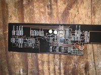
if the capacitors are inflated. (tomorrow attached photo)
the transistor of the secondary power supply looks original, the solders look original.
no, the amplifier does not turn on without a remote.
the transistor of the secondary power supply looks original, the solders look original.
no, the amplifier does not turn on without a remote.
LM324 Voltages:
with remote connected:
1: 12,6 - 8: 13,10 - 12,6 (oscillate voltage)
2: 0 - 9: 5,7
3: 6,35 - 10: 10,7
4: 0 - 11: 0
5: 6,19 - 12: 3,68
6: 5,1 - 13: 5,35
7: 12,5 - 14: 0,91
no remote but amplifier still on:
1: 0 - 8: 13,20
2: 3,68 - 9: 5,69
3: 0,55 - 10: 10,17
4: 13,82 - 11: 0,04
5: 0,56 - 12: 3,68
6: 5,10 - 13: 5,35 (gradually drops to 0v and amplifier turned off completly)
7: 0,01 - 14: 0,91
amplifier turned off completely:
1: 0 - 8: 13,62
2: 3,67 - 9: 5,69
3: 0,55 - 10: 10,17
4: 14,37 - 11: 0,04
5: 0,56 - 12: 3,68
6: 5,90 - 13: 0,3
7: 0,01 - 14: 14,09
Last edited:
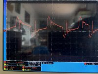
Removing the C401 circuit, the amp turns on and off normally, but I still have the 7 amp idle current problem. in addition to a strong "POP" when turning on the amplifier.
The rail voltaje is +81v and -81v
Is the power supply pulse so strange?
The rail voltaje is +81v and -81v
Is the power supply pulse so strange?
Attachments
Last edited:
The amp doesn't have negative rail.
Initially, it had a turn off pop. Is it now a turn on pop?
Confirm that all gate legs look the same and post a waveform from that point.
Check the drain resistor for C401 and replace if out of tolerance.
Initially, it had a turn off pop. Is it now a turn on pop?
Confirm that all gate legs look the same and post a waveform from that point.
Check the drain resistor for C401 and replace if out of tolerance.
I don't quite understand the difference in pulse width between the pulses.
The 196kHz is also too high. Measure the frequency at the output of the driver board or driver IC.
Check the drain resistor for C401 and replace if out of tolerance.
The 196kHz is also too high. Measure the frequency at the output of the driver board or driver IC.
Check the drain resistor for C401 and replace if out of tolerance.
You'll have to chase down the resistor. It will likely be well over 100k and will directly connect across the capacitor.
If the frequency is actually 196k, I'd suspect that the timing resistor, deadtime resistor or timing capacitor on the 3525 is out of tolerance.
If the frequency is actually 196k, I'd suspect that the timing resistor, deadtime resistor or timing capacitor on the 3525 is out of tolerance.
Hi
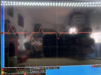
I have replaced C702 (1nf it is not out of value, but I have replaced it anyway) connected to pin 5 of 3525. Now the idle current is 3.2 amps (normal for this amp).
The transistor of secondary power supply, no longer heats up.
I get this waveform at the main source ... is it normal considering that it uses transformers to boost the pulse signal?
Attachments

If you replaced it and it was not defective, you could have some intermittent problem.
35k is far better than 200k.
The waveform is OK.
The transformers are used because the FETs directly connected to 12v have to have a floating signal. In the attached datasheet, figure 13 shows half of the circuit. All of the circuit in the rectangle would be duplicated and the FETs in the duplicated circuit would be in place of C1 and C2.
Attachments
- Home
- General Interest
- Car Audio
- JL Audio 1000/1 high idle current