NAD 326 BEE Power LED blinking RED

Hello, sorry if this has already been discussed, I searshed the forum and got no result.


Bought a second hand NAD 326 BEE (now I understand why it was for sale ...), and it does not operate correctly.


After power on, while it is cold, the power led immeditly starts blinking red, even with no speakers connected.


This is not systematic. Semetimes I can get sound for some minutes, then it falls.


This looks like a protection circuit that is not operating well.


Looking in the web it seems that this is very common on this model.


Is there a know solution to this ?


Thank you


Elan

Help with broken Hypex mono amp please

Hi All,

Happy to have found my way to this forum, have had a few great reads already, there's clearly a wealth of information and good people here!

I'm new and as you're about to learn, don't know what the hell I'm doing, so apologies in advance 😕

A few years ago I purchased a couple of beautiful sounding (to me at least) Hypex mono amps second hand. Love them to bits. I'm an idiot, and recently removed the banana plugs at the speaker end not realising the amp the cable was connected to was still turned on. The banana plugs touched, no idea for how long, but that particular amp no longer turns on.

Now I'm not definitively sure this is the cause, but presume so. I removed the lid of the Ghent audio case (quite nice btw) to test the ceramic fuse with a multimeter. Seem to be fine.

The reality is, that's the extent of my knowledge and ability when it comes to electronics, aside from giving it the ol sniff test as an indication as to whether I've fried anything (doesn't smell like it).

The build I have is NC400 and SMPS600 based. Not sure if there's much else I can provide but happy to of course if I can. I have tools: soldering iron, a basic multimeter etc but again, have no idea what I'm doing. Are there some basics I should try myself before taking to someone who knows more than me and paying them to fix?

Thanks all 🙂

How to use Philips Jupiter 404 output transformers?

I have a combo of output transformers from Philips Jupiter 404 stereo radio.
I'm not sure if/how they may be used for EL84 SE amp. The connection in the radio is a bit unusual (to me). Could somone explain the output stage of the radio and how these transofmers can be used to build EL84 SE amp?

Thanks!

Attachments

  • 404 output.png
    404 output.png
    113.3 KB · Views: 269

Speaker measurements using a laptop?

I'd like to take some measurements of my IPL M3TL transmission line speakers.
I have never taken any acoustic measurements before of ANY loudspeaker.
I only own a Dell Precision 7510 laptop (Windows 10).
I know I would need some kind of external USB audio interface/sound card.
I'm thinking of buying a QuantAsylum QA401 audio analyser (mainly for its ability to measure distortion). Could this be used for speaker measurements? Are there any other hardware/software combinations that would work. Thanks.

Tube phono MM preamp and tube buffer

I am selling the following modules as seen in pictures:

- tube phono MM preamp with PCF802. Al components are new and very good quality. The sound is fantastic and the price of the project with this module very low comparing with the sound quality. Price - 80 USD

- buffer with ECC81 Valvo. Can be adapted for ECC82,E82CC, 6CG7. Price - 80 USD.

With each module I will send a pair of NOS tubes tested (PCF802 military tubes, ECC81 Valvo - as you can see in pictures).

For any questions or details, please send a private message.

Phono stage:

IMG_0825.jpg


IMG_0826.jpg


Buffer ECC81

IMG_0842_1.jpg

FS: Kit for TDA1387 X8 NOS DAC with DIR9001 and tube output

For sales one kit for TDA1387 X8 NOS DAC with DIR9001 and tube output PCB.

You will receive (see pictures):
- one module with 8XTDA1387 with all components. As you can see in the pictures I used very good quality components;
- one SPDIF input module with DIR9001;
- one PCB for tube output (no components).

For all above the price is 110 USD + Shipping only in EU (aprx. 20 USD).

I can offer the complete output module with NOS tube 6N2P (please ask for price).

DAC-TDA1387.jpg


DIR9001.jpg

WTB or trade SBAcoustics SB29NRX-00 Passive radiator

I have a pair of SB29NRX75-6 New condition in their box. They are posted in another thread with some more satori stuff.

I got these to build a Troels SBA10 or a 3rd way for Jeff Bagby Kairos (or Adelphos or continuum) but I have switched the project due to a lack of space.
They are new in their box. One of them only opened to be pictured. The other one was installed an measured in a test box. Just a pair of sweeps. Like new.

In EU they are sold for 150 euro each plus shipping. I would trade for a pair of SB29NRX-00 passive radiators or sell them for 175 € plus shipping and PayPal fees if apply.

Im based in Spain

An externally hosted image should be here but it was not working when we last tested it.

An externally hosted image should be here but it was not working when we last tested it.

An externally hosted image should be here but it was not working when we last tested it.

An externally hosted image should be here but it was not working when we last tested it.

An externally hosted image should be here but it was not working when we last tested it.

An externally hosted image should be here but it was not working when we last tested it.

Rockford Fosgate T1500-1BD

What is the purpose of the large cap that sits behind the speaker terminals ?

Also U1

The amp was playing fine in the car is what the guy said .

He wanted the power block replaced since the power wire connection wouldn’t tighten down fully .

I opened up the amp and the large cap marked 106 was melted and I found U1 like this

Attachments

  • D6BC5608-10E6-4DEA-8BA2-02EBA8E51F5B.jpg
    D6BC5608-10E6-4DEA-8BA2-02EBA8E51F5B.jpg
    1,006.4 KB · Views: 108
  • 34A934E0-B5A8-4CCB-ABDA-832B225E1A47.jpg
    34A934E0-B5A8-4CCB-ABDA-832B225E1A47.jpg
    1,006.9 KB · Views: 118

Using DSP with full range

Using DSP with full range - two parallel drivers?

Just spinning around an idea about a new build and happened on the Dayton DA115 4" driver.


Original plan was to use it only as a woofer but looking at the FR graph it seems to play almost full range pretty smoothly. Seems like all it would need is little correction in the upper range.


Is it a bad idea to use DSP to correct the upper range and use it as a full range? So far I've only used DSP for lower end corrections where it works nicely. Of course passive crossover could manage as well as the corrections are not overly complicated.

Attachments

  • 20200719_073633.jpg
    20200719_073633.jpg
    158.3 KB · Views: 825

Fixing my system on a tight budget.

Before the world went pear shaped I was in the process of putting together a new cinema sound system in my living room. Currently I have a Marantz AV7703 pre-amp and my plan was to build a nice multi channel amp to plug into it.
Currently my amp is an old yamaha dsp75se receiver just using the multichannel inputs.
So my question would be is it possible to rip out just the amp part of this receiver and utilise it as a slightly better amp for my speakers. I have had a look at the service manual but cant get my head round it. The Yamaha amp is very old but until the world gets back to normal i'm in no position to spend big money building a good multichannel amp. So I think my best option is to try and make a multichannel power amp from this old Yamaha receiver.

I'd like to start a "Karlson compendium" thread

It would include:

All findable/known/generated plans for heritage Karlson Ultra Fidelity series.

Plans for variants (Karlsonator, XKi, etc.) from GregB, XRK971

Subjective remarks

Any history.

Files to print.

Analysis via Akabak 3

Patent and related patent lists.

Hints oh tuning. Driver recommendations.

Any reasonable hornresp fudges to give some idea of what's happening.

Can you folks think of more or better organization? How about something - Karlson-ish which you built that turned out well?


My mail box is full (with some mail to keep) and won't have money for ~17 days to expand its capacity, so reply to this thread.

My good K-friend Moray James had a stroke in July and now back in the hospital. (there's a GoFundMe for Moray) I've got old age problems, outgo more than income (taxes and insurance) - like many and would like to gather stuff for new folks.

Fundraiser by Rachel Zhang : Support Moray to go through challenging times

THANKS,

Freddy

200W 70V Mono Grommes Amplifier

Hi,

I'm in the process of fixing a specialty audio system and have discovered that the Grommes continuous duty 70V power amplifier in question is damaged. The amp had a blown fuse on one leg of the bias supply. Fuse blows immediately potentially suggesting a shorted output transistor. The other supply leg seems fine.

There is a monitor speaker and it was producing a repetitive chirping noise along with a sparking seen in the surge arrestor device that sits across the 70V output. The system was immediately shut down.

I have a few questions for the more seasoned experts. This amplifier is around 20 years old, and the design is fairly straightforward and robust. My question is whether I can determine if the failure is simply due to age, or if another factor (bad 70V driver, surge, lightning, or something else) could have caused it.

The desire is to repair (and future proof) the amplifier given that this design is reliable and parts are available. The output transistors can be sourced and I can replace all 6 (two sets of 3) for about $60. The bigger question is if I should be looking for other failed parts or anything else that might do well from future proofing aside the obvious (electrolytic capacitors). Even if the other set of 3 transistors appear fine, would replacement be in the best interest of future reliability?

Thanks for any advice! Schematic is attached.

Attachments

  • Amp Bias Supply.png
    Amp Bias Supply.png
    699.4 KB · Views: 446
  • Amp Schematic.jpg
    Amp Schematic.jpg
    124.1 KB · Views: 449

Majestic MJA 4000.1d Diode D2 ID

Hello
I need help to identify the type of diode on the driver board of a majestic MJA 4000.1d model
D2 is the one looking for the information.
It is related to its connection with R46 of 4.7 ohms that I found it resistor open in a first review. Then I measured the diode D2 and it is shorted

Attachments

  • D2 R46.jpg
    D2 R46.jpg
    860.2 KB · Views: 89
  • majestic MAJ 4000.1D.jpg
    majestic MAJ 4000.1D.jpg
    700.5 KB · Views: 114

FS: Heathkit Pair, AA-15 Integrated, AJ-15 Tuner, Wood Cases, GORGEOUS, MASS

Selling as a set.

Healthkit AA-15 integrated amplifier. All functions work perfectly. Dials could use another shot of DeOxit, but they are very functional as-is. At 75 watts per channel, this amp is no slouch. Beautiful black Plexiglas front gives it a sort of McIntosh-y look. Sound is very comparable to a vintage Pioneer from the same era. Healthy bass response.

Healthkit AJ-15 tuner sounds fantastic. All lights and functions work.

Wood cases are in nearly perfect condition. Come with both assembly manuals, including notes from the builder.

$600 for the pair, or reasonable offer.
COVID-avoidance demos available in Lawrence, MA.

50382930168_4e3c275d6f_b.jpg


50383806802_3b49c6e8e5_b.jpg


50383628761_aefe0565da_b.jpg


50383628616_ea868c5bd4_b.jpg


50383628476_cd6ef558a9_b.jpg

cartridge loading with connection cables

Is there anything wrong if the whole value of the capacitance needed to load a cartridge would be made from the cable capacitance between cart and the phono preamp?
I have some 2...3meters long very high quality 75 ohms video cables with BNC type sockets at their both end which have about 170pf each and i was thinking to use a multiple input BNC sockets stack with all the sockets wired in parallel so that i can attach more cables to it and thus form the needed capacitance while i'd connect only one cable at a time to the turntable leaving the other cables connected only to the phono input so that all the cables in parallel to give the needed capacitance to load the cartridge.

Quad II questions

Hello,

I've got a pair of quad II's that I've been refurbishing and I have some worries about the results :
Both amps have all new resistors, bias bypass cap and C1. One amp has a pair of new matched Marshall KT66 and the other has a new old stock pair of Tungsol KT66 that came with it and probably aren't matched.

One of the issued is a flash at power ON at the inside base of one of the EF86 input tubes (not on the socket).

The other is that one of the KT66 has some very light red plating after a few minutes warm up and that goes together with 6V on its grid (11V without the tube so probably faulty coupling cap ??). The other tubes have around 1V so also a little high. I will probably replace all four coupling caps but I'm not sure to be able to get metal boddied caps so I'll add a little 33pF to ground from the grids. Any suggestions on what caps to use or will any good MKP at 250v or more do the job just fine ?

Also I've read almost anything and its oposite on blue glow, all four KT66's have both a dark blue glow on the glass, a little more purpleish on the Tungsol pair and a light bright blue glow inside the plate cage. I'm pretty confident the glow on the glass is normal but I've read the inside shouldn't glow and is probably a sign of a gassy tube which could also cause the red plating.

If anyone can clear this up for me that would be great.
Thanks

Attenuators #1: Autoformer

Hi friends

As I'm knee-deep into building stuff and want to get even deeper into, I started to experiment with various types of attenuators.
I couldn't resist the temptation and got myself 2 Autoformers to make an attenuator from it. The look very techy (not nifty/glossy/...), just 2 ugly, black-painted trannies with 24 wires (in groups of 3) coming out 😎, but it came without further explanations.
Although I'm quite sure I'll get the needed assistance from the seller, I still wish to more or less understand how I'd do it.

If I was to find the order/sequence of the wires, how would I do it? Something like feeding it with a steady signal (like, x kHz 0.1V) and measuring which wire returns what?
And how would I hook them up to the switch? The schematic according to acoustic dimension seems very simple and straight forward, so... it can't be too difficult. A 2-deck 24-points switch is what I need, is that correct?

BIG thank you
david

Attachments

  • STH20.jpg
    STH20.jpg
    76.7 KB · Views: 273
  • AVC-28-02-schematic-500x530.jpg
    AVC-28-02-schematic-500x530.jpg
    42.6 KB · Views: 277

Univox u-305r

Hey everyone, im new to this forum and to tube amps in general. I have been playing for about 15 years and i just picked up my first all tube amp. I picked up a univox u-305r that has a 15" jenson speaker. This amp is currently not in working condition, all the tubes are gone, the reverb tank is not attached, i can see a couple wires coming down from the chassis. I decided to buy this one for 100 as a project to work on. After a week or so of looking on forums, youtube videos wiki and everywhere else i can think to look i am coming up a bit short. Does anyone here know anything about this amp. I cant even figure out the wattage this amp produces. I did find one wiring diagram that i think is it, but i cant varify the diagram anywhere. I did try and do a search on this forum but for some reason i cant get the search bar to work, maybe because im using my phone. Anyways thanks for your time reading and any help on this build whould be much appreciated. Thanks everyone.

Uniguy

ISO TANGO (Hirata) NC-20 Interstage Transformers

SOLD. This item has been sold.


EXCELLENT condition ISO TANGO (Hirata) NC-20 Interstage Transformers. Quantity 2 (sold as pair only).

$600 OBO

Less than 1 year old. Considered to be the best interstage Transformers on the market.

Includes 2 interstage Transformers, ISO Tango sticker and specifications sheet.

Shipping charges for shipping outside of the USA will determined at time of sale.

Contact Pat at banpuku@mac.com

Attachments

  • Screen Shot 2020-09-25 at 4.49.45 PM.png
    Screen Shot 2020-09-25 at 4.49.45 PM.png
    278.9 KB · Views: 192
  • Screen Shot 2020-09-25 at 4.50.18 PM.png
    Screen Shot 2020-09-25 at 4.50.18 PM.png
    14.9 KB · Views: 200
  • IMG_0920.jpg
    IMG_0920.jpg
    905.9 KB · Views: 195
  • IMG_0919.jpg
    IMG_0919.jpg
    983.5 KB · Views: 197

Does adding mass to a voice coil reduce its BL?

Hi,

Does adding mass to a voice coil reduce its BL?

I was looking at T/S parameters of some of the competition sub-woofers and noted that though some of them have huge magnets, but they dont have particularly high BL, I mean they do have higher BL than non competition subs but its not that much high. In order to make the sub in a smaller box these competition subs have high moving mass and that raised a doubt: is the added mass somehow reducing the BL?

Thanks and Regards,
WA

Damage to amplifier WITHOUT NACA5, A4, Linn K20 etc?

I have read a lot of opinions that state the need for the above cables when using Naim amplifiers.

I know that some people also say if using any other cables they need to be carefully matched to the amplifier with attention being paid to inductance and other things.

These opinions/beliefs seem to be held with varying levels of importance from person to person.

The question I would really like answered definitively is, can speaker cables, any speaker cables actually cause physical damage to a Naim (NAP90/3 - amp in question at the moment) olive or before amplifier (or speakers for that matter)? Or are the such strongly held preferences of some Naim enthusiasts purely from an audible (not unimportant in itself either of course) point of view with just a 'belief' that harm will be done if Naim's advice is not adhered to?

😕

What are some other good websites for multiway information

There is a lot of good information here, but I'd like to see even more on the same subject. And not all necessarily from a DIY perspective.

I've been looking at audiocircle.com for a while, but can't believe the amount of snake oil that exists there. Particularly with regard to cables. Apparently some of the 'circles' are paid for by manufacturers and they can say just about anything they want and can't be challenged. If someone does challenge them the board 'nazis' squelch it in a hurry.

So what are some of the other websites for high end audio that others are using these days. Thanks.

DIY MC Cartridge

Has anyone thought about building a MC cartridge from scratch? Has anyone else tried?

I'm looking at something like
ON Semiconductor EMI9404: 4CH EMI LC Filter with ESD Protection
for coils.

It's actually copper coils integrated onto an IC with zener diodes. These are in plastic packages, but there are chip scale coils too which are much smaller. The roll off of the filters is in the megahertz, so that's probably not going to be a problem. They're great at filtering out GSM cell phone noise. There's a surplus place here with Litz wire and the individual strands of enameled wire must be about AWG 63 which is small enough to solder to the IC's.

for a cantilever
Amazon.com: Translucent Amber Miniature Polyimide Tubing, 44 AWG, 0.0020" ID, 0.0030" OD, 0.0005" Wall, 30" Length: Industrial & Scientific
which might actually be too thin. The filter IC's would be glued edge on to the cantilever. Since the chips are half a mm tall, that would be a good diameter for the cantilever.

A couple of these
SuperMagnetMan Ring Magnet
would make a field for the coils to live in.

I have no idea where to get a diamond tip. There's a guy in New York that re-tips cartridges for $250, but that's a pretty steep experiment. A cheap-0 cartridge or needle from Radio Shack might be a good donor to start with.

Anomalous REW driver readings? 2-way design help!

Hello! I have taken the deep plunge into loudspeaker design and theory over the last several months. These forums have been invaluable to my growth in understanding. Thank You!

I have a puzzle regarding the measurements I obtained yesterday in my attempt to get raw driver readings with my new drivers in a test speaker cabinet.

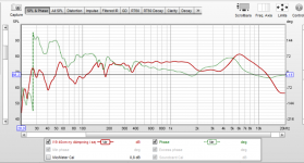
In reading the thread "So you want to build your own speaker from scratch" I thought I was setting myself up for audio bliss and a deeper understanding of the science of acoustic measurement and engineering. I bought the test equipment (including the Dayton DATS v3 which gave results that agree very well with manufacturer spec) and have been practicing using 3 different crossover design software programs in anticipation of these measured results... These disappointing measurements when loaded into my crossover designers COMPLETELY change what needs to be done to achieve a flat response. So much so that I have very low confidence in the results.

Rather than trusting the measurements here I thought I would reach out and ask for some assistance on the causes of these anomalous results. If we finally determine the measurements are good... I have some serious questions on how to proceed with the crossover network development that I would love to talk about! But first I need help establishing confidence in the measurements and their interpretation.

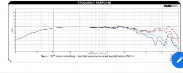
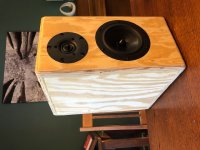
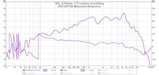
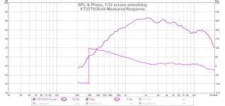
I chose these drivers because of their nice linear responses. The measured responses I got were FAR from linear. Below about 500 Hz I'm not really concerned due to the set up involved and the cabinet being ported out of the back. I did expect some baffle ripple effects (1K- 2.5K) and beaming. This is why I tested the drivers in a mock up test box with the actual baffle design and volume/ tuning I expect to use in the final version. So... now that I have a HUGE hump in the tweeter response and an extreme sloped response from the woofer how should I proceed? Starting a High Pass filter at 9K seems a little extreme... maybe it isn't... Please help!


The Results: I have included the REW graphs with 1/12th smoothing and phase. I am comparing these to the factory specifications also linked below.


The Measurement Setup:

---Laptop ASUS computer running REW
*headphone out to RCA jack set to "Speakers" mode

---Emotiva Mini-X A-100 Stereo Amp

---Pyle Microphone USB pre-amp

---DBX RTX-M omnidirectional measurement microphone

---Outdoors "Anechoic" measurement attempt

---Speaker on 7ft ladder with mic placement on center of driver 3 feet away

Drivers in Question:

Tymphany XT25G30-04: Direct signal sweep from 200 Hz - 20 KHz

https://www.parts-express.com/pedocs/specs/264-1016--tymphany-xt25tg30-04-spec-sheet.pdf

Dayton Audio RS150P-8A: Direct signal sweep from 20 Hz - 20 KHz

https://www.parts-express.com/pedoc...rs150p-8a-reference-series-specifications.pdf


The amplifier gain was unchanged as I switched between the drivers. I did not do a test with both operating concurrently.

The Cabinet:

15 L with a 2" (51mm ID) port tuned to 49 Hz

Overall baffle measurements = 381 mm X 203 mm

The edge is a 1/2" (13mm) round-over

The tweeter offset 75 mm from both the left and upper edge.
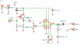
I can include a baffle diagram if that would be useful.

Thank you so much for all of your help! I can't wait to have a deeper understanding of this fascinating subject.

OrionX76

Attachments

  • 2-Way_Test_Box.jpg
    2-Way_Test_Box.jpg
    87.3 KB · Views: 415
  • RS150P-8A Measured Response.jpg
    RS150P-8A Measured Response.jpg
    153.5 KB · Views: 436
  • XT25TG30-04 Measured Response.jpg
    XT25TG30-04 Measured Response.jpg
    130 KB · Views: 423

Cambridge CP1 upgrade

I've finally finished the upgrade.

First I removed those stupid 220pF loading caps from the input.

Oh man, that changed everything...

(free)

Then I replaced the original TI NE5532P op amps with TI LM4562NA
(£7.26/3pcs + sockets £1.31/10pcs)

AJ3dosy.jpg


The result was huge, the new op amps opened up sound stage, everything was much more detailed, and much more loud. It was a huge upgrade, but the sound was really sterile/cold after it. I'm still thinking to replace the output op amp with a wormer op amp.

(£6.46 and I still have bunch of caps left)

In the next step I changed the original Xunda capacitors in the PSU on the panel with Panasonic FCs. I didn't really listened it, I just checked it so I could move to the next stage which is replace the capacitors in the amplifier part.
These electronic caps has been replaced with Nichicon FG (Fine Gold) and Nichicon ES (Bi-polar MUSE). The most noticeable part was the input caps around the op amps.

After these changes, I got even more detail, and the mids were much more together with other freqs.

(£16 including post)

Finally I replaced the no-name polyester film capacitors with nice Jantzen MKT ones.

This upgrade finally brought the taste into the sound. The sound is not that sterile anymore.

(£6.60)

Final image:

fmKEy3m.jpg


So for less than £40 I got much more detail, soundstage and my sound is not that compressed anymore.

And for sure my transformer died while I was doing this upgrade, so I started to build my own nice linear PSU. Now I'm powering the phono from it.

40ZSc4a.jpg


ijghrDi.jpg

Nad C326BEE left channel pre amp problem

Hello.
Amplifier NAD C326BEE.
No sound on left channel.
Power amplifier works fine on 2 channels.
With Audio signal tracer the signal stop on Q104.
Signal ok on​ GATE of Q104,but nothing on Source and Drain .
I replaced the Q104,but not results.
Gate ok,but nothing on source and drain.
Thank you.
Regards.


SM

NAD C326BEE Service Manual download, schematics, eeprom, repair info for electronics experts

DIY electronic player for Edison Amberol 4-minte cylinders?

Are there any plans or build logs for DIY cylinder players? I would be interested in a simple playback device that could be connected to my amplifier, but I have no idea how complex this would be. I've see a number of inexpensive linear tracking turntables for sale on Craigslist. Could any of these be modified to play a cylinder? Thanks in advance for your comments!

Krell KSA50 Clone (Pink Mouse) PCBs - new.

A set of new Krell Clone (Pink Mouse) boards as per pictures below. These are the heavier, thicker trace version and were expensive! They are unbroken and comprise

x4 output boards
x2 Driver boards, attached to:
x2 Main boardsTotal x8 boards

Best offers please; I can't set a price as I cannot find the original price.

Thanks for looking.

Attachments

  • BDC_1247z.jpg
    BDC_1247z.jpg
    944.3 KB · Views: 695

Good old days!!!!

We are going through a difficult phase in our life. I hope everything goes back the way it used to be, being with friends, gatherings, marriages and so on. I was going through some photos of our last new year's celebrations. It was a star-studded musical performance with sophisticated light shows armed with lasers, holograms, projections, and backing screens. I could say that these audiovisual solutions had a significant role in creating a mesmerizing feast for every attendee on that event. Good old days!!!! I miss them a lot. How long should we wait to get over this period?

Need help identifying component

9EE26B59-4BC7-4781-BB42-C45EF6EE2145.jpg
I’m working on a Helicon VoiceLive2. It doesn’t power up. I have no schematic. It uses a working DC 12v wall wart. I traced power into unit to a surface mounted blown fuse. From the fuse correct flow goes to device Q800. I suspect it is a transistor but markings are not directing me to any part. I added a photo. It appears that from Q800 voltage goes to a LM317 and a circuit that may be a DC to DC converter (can see several coils and a filter cap arrangement that suggests a split supply).
Thanks in advance,
Fred

interpretation of measurements in rew

Hello
As you can see, my measurements look really bad.
These are made with REW, calibrated mic, focusrite sound card and a good amplifier.
The element is a SEAS L19 bass in a 19 liter box with bass reflex.
As you can see, it is very messy in the lower part (even above 200Hz).
does anyone have any idea what I'm doing wrong?
Is it the boxes or the measurements I make wrong?

greetings
fredrik

Attachments

  • L19 mätning.PNG
    L19 mätning.PNG
    203.5 KB · Views: 254

Need PCB for audio buffer to use as phono miniDSP pre amp (4.0mV to 4v input voltage)

I am trying to take the output from my Sumiko Pearl MM phono cartridge, to a a MiniDSP 2x4 HD (apply the RIAA equalization here), then to my amp, and eventually my speakers.


Any suggestions on how to take the signal from 4.0 mV output voltage from the Sumiko to the 4v required by the MiniDSP?

The RJM Audio B-board looks to be a contender but I'm open to suggestions.

2-sided board for Ruby Amp

So I've been playing around with a Ruby as an electronics learning project, and as an excuse to cut some wood. I've made myself a small fender-ish cabinet that fits baffles for 8" and 10" speakers. To drive this, i etched a Ruby PCB using the storyboardist layout from Perf and PCB Effects Layouts. It worked great for a little while until suddenly it didn't and instead produced a mid-range pitched very intense stable tone that modulated frequency with volume and gain. After some troubleshooting i believe the fault was the J201 JFET (both D and S were close to +9V) and i have a replacement on the way.


Now, i was a little too fast when making this board and didnt cut the phenolic board large enough to allow for mounting holes. So, thought I, why not call it an excuse to draw up my own layout and have the good folks at DIYaudio school me on it! Having said all this, I hope you will provide me some feedback for this layout. Bear in mind that I am a complete beginner and know pretty much nothing except the bare basics. I am still working out the wrinkles of using KiCad for example, as is probably evident already. I have attached schematic and layout as pictures. The schematic is adapted for the bassman mod (0.1 uf coupling cap from JFET instead of 0.047 uf), and is intended to have pots and other stuff mounted off-board.


Main objective is to have fun and learn something along the way. As for design objectives i'll settle for "works", but i suppose i should say that i loosely copied the storyboardist layout, with a few changes:
- Made it a little less tight to make the component choice less critical.
- Moved 9V+ and PSU gnd inputs to bottom left side
- Double sided. The backside is PSU and a large GND plane. Front is all the signal-related stuff. I don't know if this is the right way to go, but it was easier to route this way...


One question - i notice the noisy cricket has a 220 µf filter cap instead of 100. Does it make sense to increase size or is the benefit academic?


Thanks in advance for your patience and understanding... Pictures of amp cabinet to come!

Attachments

  • ruby-schem.png
    ruby-schem.png
    8.4 KB · Views: 528
  • ruby-layout.png
    ruby-layout.png
    46.4 KB · Views: 618

Comments on my Transistor Selections

I'm building two amplifiers that are similar in many ways, and would appreciate some advice.

One is a normal audio amp based partly on my own design, partly on Douglas Self's book "Audio Power Amplifier Design 6th ed.", with input from articles in this diyAudio forum and Bob Cordell's "Designing Audio Power Amplifiers 2nd ed." and from other sources.

The other is a specialized power supply whose core is a simplified version of the audio amp. Vout is +-50V, Iout is +-6A for any Vout. This can be called a bipolar power supply in terms of being able to source or sink current at any Vout.

Both use more or less the same general topologies in the core gain and output stages. I'm using LTspiceXVII to simulate.

This my first cut at building a discrete amplifier of this power, but I have 35 years of experience with major electronics companies designing analog ICs for various purposes. I'm considering the power supply to be kind of a dry run for the audio amp since it's quite a bit simpler.

At this point I'm trying to decide what transistors to use in the high voltage sections. For now I'll ignore the audio amp and just consider the power supply (which is essentially a specialized audio amp).

The VAS and output stages are based on Self's "Blameless" amplifier (cf. Self p. 311). The VAS is conventional. The output is what Self calls a CFP (Complementary-Feedback Pair).

My tentative choices are:

VAS devices: ksc3503ds ksa1381estu from ON
Drivers for power devices: mje340 mje350 from ON
Power devices: 2n3773 2n6609 (8 of each) Ebay/China special

For circuitry not in signal path: ksc2690AYSTU ksa1220AYS

Alternatives:
VAS: ON ksc2690AYSTU ksa1220AYS OR Toshiba ttc004b tta004b
CFP driver: Toshiba 2sc5171 2sa1930 OR Sanken 2sc4883A 2sa1859A

Other relevant specs:
Rails: +-54V to +-62V depending on load
Power transformer: Antek 600VA 45V (2 secondaries)
Bridge Rectifier: Taiwan Semiconductor GBPC5002 50A 200V

I will appreciate any comments.

Alan

Crossover components

Hi all,

These are parts left over after I built 2 pair of outboard crossovers. I had planned to build one more but that's not gonna happen.

Coils, Resistors, Capacitors and Heatsinks for sale. Like new and never used. No boxes.

Air Core Coils
Jantzen Audio coil L=5.00mH Rdc-1.30 ohm 18 gauge (2) $23each
Jantzen Audio coil L=0.90mH Rdc-0.47 ohm 18 gauge $7
Jantzen Audio coil L=0.872mH Rdc-0.46 ohm 18 gauge $7
Jantzen Audio coil L=0.15mH Rdc-0.16 ohm 18 gauge $5
Jantzen Audio coil L=0.11mH Rdc-0.133 ohm 18 gauge $5

Erse Audio coil L=0.898mH Rdc-.292 ohm 16 gauge (2) $7each
Erse Audio coil L=0.641mH Rdc-.242 ohm 16 gauge (2) $6 each

Resistors
Dale RH-50 50W 2.2 ohm 1% (2) $5each
Dale RH-50 50W 2 ohm 1% (2) $5 each
Dale RH-50 50W 1 ohm 1% (2) $8 each
Dale RH-25 25W 1.5 ohm 1% (4) $4 each
Dale JAN 10W 1.5 ohm 1% (1) $3 each
Dale RH-10 10W 1 ohm 1% (2) $4 each
Dale RH-10 10W .68 ohm 1% (2) $5.00

Capacitors
WIMA MKP10 47uF 100- / 63 5% (2) $45.00 each
Jantzen Audio Superior Z-cap 4.7uF 2% $28 each

Heatsinks
3 1/16” x 3 11/64” x 1 3/64” copper (2)
2.3” x 2.39” x .45” black anodized Aluminum (4)

DIY Dolby Atmos speaker

I completed a couple of Dolby Atmos speakers in past couple of weeks. These are front upward firing Atmos speakers that reflect the sound of the ceiling creating surround effect from the ceiling.

Initially when I tested the Atmos speakers, I was disappoint as I could not hear much effect. Then one day I was playing the Eagles farewell concert in DTS and my Denon automatically set the surround to DTS-Neural X. The makes the Atmos speaker playing all the time and with vocal and I can hear the singers voice from the ceiling. But the reflected sound was in front of my seating position. Because the singing and music is continuous, it makes it easy to find the optimum position where the sound is reflected. The position is a couple of feet in front of my couch. My Atmos speaker is design with a 30 degree angle and obviously that is not optimum for my seating position. So I raised the back of the Atmos speaker up and that shifted the sound further away from the Tv back to my seating position. The difference is night and day, and now the Atmos speakers effect is awesome. Now the ceiling is like a big speaker. So now settled with a 40 degree angle and they are just awesome.

The strange thing is when I design the Atmos speaker, I use calculated the sound reflection based on the speaker height, ceiling height and the listening position and 30 degree seems optimum. But it tuen out that the angle is wrong and the speaker need 40 degree for optimum performance.

Anyway, below are some photos of the speakers.


QD656VoSK1_CYXJ3sqFx74YmEAuhLbUJzqPF1S3T8CRQMZt44yGBACV9b-dmPOZ2f1bLilie3FUYqeBS-di7xTYVAqZmFED0SSMMPL3Zg3cjURhXoVL3acRwKtO4gsuwyatTHiuH1Qs3eWq5vr-CbnGJUCDuDtekqeZHLNHuldbDsUq_umrS1HiHLNpx5iTorUJj9y816NXnXQljU3_ryicIXO-9l0sbfOLgo2qGAS42OclwrcJmmhpv2PoTHuOamPujI65jNMTr-L9ZPKemVB3yyJFH9SBbOqxH9ZfozncPGWXwMic5S-9NYIBalKpcSgLaRx_lTxkET1GJcJEGUR91gPWb-874qVeHOhy_ZhxVE4hh5GPsgGLuC8Bh0XVZIG1J-9pxlWUyJrruqZ3CyZ34uv61OrlHJDVKn2UdwsUlvDr0SigVFE_isTMm4GOSvKBD9_VtWlZf7LG52OVfiO7dOBQSpIxuPWNDKw6sTmpd2e44TzGtDuyYwa3tZ_D-UOGpB9j8gLdrsbfXthQSR45CSUmVFT3UlxYOLB3bTBpCzFb50YUAGZD1VX95kWMqBgDP0WBmsH3o59bNyipeMlkjDOinsG_fRWaH0_RYfrWyV12-53QnEOOxkPwd53d6M0yCyw4xG2b6GmnuLb1HGTDhMUgwS-FV3FeR8NyoPd23muOj-4UXm4O1BMhVSQ=w960-h720-no

B4yTTFxtlNxxtZW94-K0ooCjm7fz82Fh90sJdKWXfv6PDveqeAicsJWn8Dk0V4o2lS8yNtZCPt64xdRUE1nLoiq8414d_PXnaZDQdD_NkjaRiNWQkf9DSCHKrVCMrRtKUYW_F2y7r-t0y7tjhCBmwHh0F-qQC0IQ2v7NqfXBbjqpdiMnP2k7y-zCNR1gL_pixvlnzGtedbS4w9Na-8HXHMV9WmZNpGpmm1bPn0jxKJBGcU7U9DPwefY4mPA6pPvox_KoS2dVqpipCp_Z0KZ9PI1OHJWjiFFJp21JJHLLVVp1FsDMGFxsD7EuaDdEGfqGgq1pGy5cFXt6_TQ3-nc59-xPTxtvnX8UnJ6h2R_42aUGISXMprfrLshhqqvlubELLIOf1c_ChD5e6ahR7sHvT_8nXVCbuAqOL6i29Msmz3wZDYlX7pKHY8K-4QfeQmHlpWkDP8Mh2nbQwHsRi6GfSMEhTrwdJqDke_6h81PonlQ1x--gumh5gpZk1i9kVvMYNAKrDyrVFA0d5KVEae15NF2U8xxUcVlseOrZ1bdd1Ez18AiJu2tFaLSsXmKi0NVjz1x6DmetwBwtftBktsJAl4PhpxKkCyHfetFtTvKjvykAKvc5N-ThtPaXTXzMRiM98ofcrqHaA3ggujS7jn2ZcW11_aBc8ZZszZ8NnNJLDnjCR3PnASKeTpg20UlnAA=w960-h720-no

fJdxMj72dNVNSHLWyhrR2zuGuEJPiyBkP7rtfm_v92nzTc2iYW23y1oywgupY-pZXn6_XUw0rKQXQhIvGx9YYShT3GgOk0E_c86zjfgHr7inmjWroC5-IhwgBaW0uwTAu5jkuXQSG-hzSRYXaSI-41t759Miz5ZpOGA6XHRFhYPJIjsPc4VHCTZpiuGTeu7Pg1TF3MSidOD4KIGvX3BD18GxxfzBfW1od4YA0vtEjeyKMegxqjfyU5_YrYQEgfB00Ua1lSJsPrZS4OEAxbnqzt3OyBOwFQA0zjm-BXegw7QaF9w-Ep6j3pv7tybXcT-9VkHVUsIsw5bIPlfTkacMZ287vOrNbjmiOsiSkdD_BJK9roo53KwMWBZeFCiNmhZInPpfolr4U2tpJs-SX8TC70eV9kE4I-u7CFrZilsAaNHGeoU_fNnaWDuuWl0pMdwXzwPG4JE8KDPfQF6oMFR3tcd3W60CrRULWtPzxPjJ73oVHbzs2Pn_LniNPb9de6KZY4QxHpkrBGXhdKUwyLDLAIzN8tCbZGoykQk3pycScHj4qwy-plSARJX_xy2c5LTrUCZ6XycJMRjrZHz8ky7i9DJMelg7rPhVJvx7icn4EVX5i9MXKYyUYni2bv7stNf5aHyLe2XNTMr1p4eYuVSs1s3H8LF-WVGyXvCvfrJOj1zQKgWkxGZFZvi3xpiVeQ=w1440-h720-no

rJdrittdf_K2MK3p6Nq4FTl3ivg0mcF9NFApCuI3_d4es31ZwbyuQr2oPW8Phtx8WbPmBTxo1kwh4N3oAUTFUGslNMzIOZy8pvIrvGQ1ypSMe45UjMggwDUv63r01CHwYRcbZrot6O5yhHhrhSYoVfIymSS2FCBYO3EeQ1GkIaXggJZSkqUGQhVIwwAXH95bkgAYtCVq9AvEPm4ULlJKlY4veN71lQdZWui-V9EsoVaHg0G3lriRH5UiF9uPZiGbjtp3GcvukG0iTFWV1LZ6ZbyV1E0MRmvcM7sKCqbZx91KgX4bdw61eB6Q9pVowQ6qt3NgU4UB8bDlSp0cx9p7WrY454Bu72pRX-zXfYwH352wFJA33Ra26jOERAN26zgKM-IUjWLtVzzPGXd8gO0ZcBo3hZpSpqQcwLdyTDKwIufNrkfBbIxVIzBTTVNSZx6blkw0YhlPcNgDhoUWod4gXCVCN-u_ZxGg1TRSb2iz8lr6fApe1ikSIqVCDv7Qv5l50phUZQweZrNObHGXuNleKXlyhobhF4M53Rsxv0YPt9bBDagA_lVGBBnMPmnUn5dMIbVLtz4HlSkn8KNYgTHK3rKV4ZUbX5EnMmqnXxPDege4-TAsRUNGA8vaJ5Y5MusDFjDP-U2q23ygpTsWTCPUiF1xuMXQ1l5ApfvS7r-RDrei-YnFZNisELxDQJx6fQ=w360-h720-no

VQxkfsR9bl7cAy4ZaLfccRBYt9IHOGWDelG_FV9Aa3zi9p8yn9Yvs9GKSX3sKnr9qxUmHRNQY6yl39F8Kb41p_jm1D1YF_wvgbKho6IYQmDPL7GqjTUgP408gTp2ifBd9EPpiH9NgN13Te_nmgBgK16nnRdmrc8xE_LcFdTChEKoaZtJu4odckjwimwNsqmBwAoIeqIsDs_MHF3mgmaOY46jcU8gJQdV-BKoRi1OVZDGqdHH10izGrXeGOe2EuSp0PS2df0OKHq2-RezQmapResknLAQ8NPHH1ML_3BkhIzmBCPo9ELFs1-vDJg87JRvYbO7H2JU_aqODZjvVQXlT_w9ZAgqDULqWOmbaeVa6vIgLvx04aSYGB5q3svbt2D_cbquk5GVs_tvLA2jVTlEeV1cOB_8nfVlm9t6Tx-D_GWJXhAbkw39EZV0lGL_X1GjHMX9OFktSh91GLR-gBh-QCQRtnXWDJXXC3UVQ2fjVxoGXfZYrAVbIrtQ_X2jdw807IPaqEmG5-DcDDG54-zMkoJ_unX3j22qoqPygXhFmKzvwQIHPFIz99E1_8MwWxeG6LbILEq1lKBp9Yix7Dcr1lHhGle8FIv_ki1_Krh3ntqbT2NufRcsPfNurt-ZSL5KUo19QAAh2JXpK_CTnD8v1GVCXyNw9-N1is-x3bJAG9OvdavYcCHp9Z7WzGEDIQ=w960-h720-no

NeHGat0ssMAZJ1-6RV48sPPKtJ-6eMHxJX-pDZ8KPERBkfRHU5SEZpUNyhm_VRTd9IpefU1rlLh_xWLB0zICt9jqpLtHILsl0HI_Jy1XhN6RvUOIiN0HBMK4hLCIfE1StFQpOmcLenA7-eqWGOUahlqduz2A52T7VYDVauPbG5s0IBv7undtbi36ZHaBRWT_vF12a3WV9P9Uw9X_iodfSMfXZhwKBDAd8LyO4T2KLD66IEcouLVfS051usOrpc5di7gCTtYzFKX-58PPoIH2WJk9FidhLZaS6dio6q4Gkm1nlVNq5EK4ASGakkNcCi2xhliBYRM8tQD6tTu6dUuESQz1Yp5jip2OWG1ruhJ3IKi5xZuAg77psOozm2dnO5uYvE1mdyRyEcIzw77SJJwyZM7rVm6ibiSv0hwIjxzy9HI6fNdaRSdsSp5kJs9i3mP4P8OCsd6BJhQHKYCcWyAE-1ku_G4QtfvwvseChOsb-MjduS9j-tVND2P1FNX0_rh-wTvTn5Mp9RJ-rgSYGew7EPyTfQpCoG4t0_TmMnzA9sD5exnTvsj-hoZmaLgSXKavnBNjQGwqZRY_iL4u9ZbB6PAEg3K0HA_RMxwVAJCZwmVhyoPzPRQT2vCXeZ9pH-7ZX_0mZg82mbSwXqNl-hRtT6meCk7bqrbhOu5V2-1NIlbgmU4Mgk3GZLQ4cb4O_g=w960-h720-no

Is there a waiting list or similar for the upcoming Pass Vfet kit?

Hi there,

I understand there's going to be another VFET kit coming out of some mysterious and as yet undefined amp. I'd anticipate a bit of a feeding frenzy, so I'm wondering if there's a waitlist of any form likely to be happening?

I for one would be a little disappointed if I just happened to not log in for a few days and missed the boat!

I reckon there will be a few folks quite interested so wondering if there could be some description of the likely process?

Thanks kindly!

Picking substitute jFet and correct bias

I recently built the PASS 6-24 Diy crossover. I got two boards to do a three way but figured it's also an opportunity to build each one with different jFets in order to see if I can actually hear any difference between the kit's J113 and the suggested substitute -SK170.

The J113 with datasheet ldss of 2mA is biased at about 8mA with a 100ohm resistor and roughly 22VDC across two of these in a vertical series pair, the lower as a CCS the upper as a follower. (So roughly 11VDC across each jFet/Rbias.)

J113 DataSheet. ------ LSK170 DataSheet. ------ PASS 6-24 DIY Manual linked from Post #1 of thread.

My question is which grade of LSK170 would work here ? I made up a jig for B versions but at 12V across it, the most current I can get is ≈7mA with Rs=0, Vgs=0, Vds=12V.

I'm having trouble connecting the dots with the two different devices' Idss and their expected operating points . I have read a couple of web pages on jFets , one being Erno Borbely's page but it just aint clicking and need a little help. Anyone got a little light to shine on it?
Thanks !

Parasound HCA 1000a amplifier

Parasound HCA 1000a amplifier

Should we start a web-site just for Parasound HCA 1000a owners and fans?
I just got one used and out of the box it was great - then I re-capped with matched capacitors+ - .01 percent, as I do. Then by-pass with .5uf polystyrenes. Well, what a piece of gear this amp is, air, imaging, neutrality, dynamics, on good material (musically, not engineering wise) - I think it is the ultimate best buy. I've listened to some expensive new stuff lately (which I could never afford by the way), and real amps not Class d, and this amp is easily in their league. John is a master, we know that, but like Pass he does it for the people who need affordable as well. Thank the stars for democratic audio designers!
Garnet Lewis aka analogue11

Attachments

  • a parasound hca 1000a 400w 4 ohms cap updates 3.jpg
    a parasound hca 1000a 400w 4 ohms cap updates 3.jpg
    398.8 KB · Views: 290
  • a parasound hca 1000a upgrades 4 (2).jpg
    a parasound hca 1000a upgrades 4 (2).jpg
    566.6 KB · Views: 291

Parasound HCA-1000a Refresh

Hello, I haven't posted here much but visit from time to time.

Previously I had re-caped a Parasound HCA-800ii and C/PT-600. I had found that about 1/3 of the electrolytic caps had gone out of spec. The signal path caps were replaced with Nichicon FG and KZ. The improvement was quite dramatic. The background is now very dark and imaging with my Polk LSi-15's is fantastic. I know that these are rather lowly components in the Parasound line but they are enough to make me a fan and I plan to move up the Parasound chain as I am able.

I recently picked up a Parasound HCA-1000a for very little $$ that needs a little help but still sounds good in spite. I was trying to hold out for a HCA-1200 or 1500 but couldn't pass this one for the price. There were things that bothered me about the HCA-800ii layout that seem to have all been addressed with the 1000a. The build is very beefy and I love the symmetry. I look forward to restoring it to glory even is it is also on the lower end of the line.

The amp looks to be in good shape except for some bad solder joints and the power supply caps are bulged. There are four Elna 10000uF, 63V. I saw mention of increasing to 15000uF, 80V, however, the ones that I have found look to be physically too large. It looks like I can go 35-40mm dia x 70mm high. Any recommendation for replacements?

As this amp has some age, what other items should I consider replacing?

The PCB is pretty dirty and seems to have a cruddy film (smoker environment). Is there anything I can safely use to clean the board or should I just leave it alone?

Thanks in advance
Stan

speaker dc protect modules

i have 4 of these modules.
2 have uk mains transformers and 2 require a separate mains transformer each.
protect led indicator.
150wrms into 4 ohms max or 300wrms into 8 ohms max.
£12-99 for uk mains version.
£9.99 for ones that have no mains transformer onboard. need 0-9 0-9vac 2va or more transformer. note you cant use one transformer for both units.
postage is £3.99 to uk. £12.99 to usa and £9.99 to rest of world.
pm me if you interested.
dcss.jpg

Sony PS-X600 Turntable Power Supply Problem

I hope I am posting this in the correct forum. My logic is that it is a power supply issue I am trying to resolve first. If this should move to analog sources please let me know.

I have a Sony PS-X600 turntable that I purchased back in 1982. This is a direct drive table with a Biotracer arm (motorized). The arm moves erratically shortly after powering the turntable on - it works correctly for about 10 to 30 seconds. The arm position is determined by LEDs shinning through slits to photo detectors which count the slits to know the arm position.

Before working directly on that issue, I thought I would measure voltages in the power supply (schematic below). If the voltages are off it could affect the LEDs and photo detectors. Mostly the voltages are as shown on the schematic. However, +-30 VDC is really +24 and -26 VDC. Given this issue, I thought I should address the power supply first. I note that the +-30 VDC is derived from a 50 AC secondary off the transformer coupled to a bridge recitifier (D101-D104) and two 1000 mF capacitors. My plan was to replace the diodes and the capacitors to get back to the +-30 VDC. I have several 1N4004RLG diodes and I am wondering if they will work. Since the power supply is only driving motors and digital circuitry I assume it is not as demanding as for a preamp or amp. For the capacitors I was planning on using Nichicon Mouser part number 647-UPW1H102MHD1TN 1000 mF 50 VDC.

I am also planning on replacing all the other electrolytics in the power supply. I was going to use Nichican UPW for most of the caps and Kemet film caps for the two .47 mF 50 VDC capacitors.

Should I also consider replacing the transistors in the power supply? If so how can I find substitutes since the original parts are no longer available? I can find cross reference listings but I don't know which parameters are most important. And will the 1N4004RLG work for diodes D107 and D108?

Thanks in advance for any help.

Attachments

  • Sony PS-X600 PS Schematic.jpg
    Sony PS-X600 PS Schematic.jpg
    323.7 KB · Views: 289

  • Poll Poll
Hammond vs Edcor power transformer quality

Hammond or Edcor

  • Hammond - it is a better quality

    Votes: 6 20.0%
  • Edcor - it is a better quality

    Votes: 5 16.7%
  • Hammond - trusted brand and fixed heat issues last few years

    Votes: 4 13.3%
  • Edcor - same quality but cheaper

    Votes: 7 23.3%
  • Another brand, please post what and why

    Votes: 8 26.7%

Eight years ago I bought a Hammond 370FX. It ran cool and was quiet. Four years ago I bought the 370KX and it was nosy and ran incredibly hot (still within temperature limits) at half rated power for HT and for filament.

The 370FX has a 30uF motorun capacitor as first cap while the 370KX used (as per Audio Note design) a 220uF as first capacitor. Due to the voltages needing dropping some 39 Ohm resistors were put in series with each of the diodes on the 370KX yet no difference in temperature.

I have a need to replace a power transformer - which one would you go for, which has the better quality, has Hammond improved?

FS: Matched quad PS Vane EL34PH

Hello all,
moving away from Stax cans so I don't need the upgraded tubes I bought for my Woo Audio WES.

First to go is a matched quad of PS Vane EL34PH. This is the replica of what is widely considered the grand daddy of the EL34 types, the Phillips Holland metal base. These have less than 50 hours on them. They made a great improvement over the EH6CA7 that came with the WES. Comes with the box and test cards.

Originally paid $ 295.00 for the quad. Will take $ 125.00 plus whatever insured shipping is to get it to you.

I can't post pics on this site. Send me your e-mail and I'll send them to you directly.

These are great sounding tubes in the WES, but I don't like the Stax sound, so they go. More WES tube upgrades coming up.

Thanks for looking,

Cheers and be safe, Crazy Bill

Simulated Triode (Schade) SE OL Headphone Amp

Attached are pictures of a PCB I ginned up over last weekend for an open loop headphone amp using a mosfet with feedback to simulate triode characteristics.
Use of a solid state "triode" allows one to bump up the bias current and avoid use of an output transformer. I could do the same thing using a real vacuum state triode, but then would be stuck with an expensive and heavy output transformer, or, for a parafeed solution, an expensive transformer plus a tubby coupling cap. The goal here was a headphone amp with good listening characteristics with less-than-stellar THD, just like your classic triode open loop SE setup. Simulation shows dominant 2nd harmonic with decreasing high order products. I decided to pump up the bias current to reduce the THD, up beyond what I would actually need for power delivery into a headphone load of 30-50 ohms. If I were using an actual triode, most likely the power for the filament(s) would exceed the power dissipated in the whole amplifier.

For this board run, I decided to use yellow solder mask for a different look, along with black silk screen. The actual results surprised me, as the yellow solder mask turns out to be a lot more transparent and subliminal than expected, allowing me to see the traces clearly. The black silk screen has excellent readability.
For this first approach, I decided to backtrack to an earlier triode emulation circuit using a jfet and a mosfet. I may also entertain the possibility of using a later implementation using a p-channnel and n-channel mosfet, as it allows me to use a pot at the input to control volume. I could use a pot with this design, but the resistance value would be inconveniently low.

Attachments

  • Img_2848.jpg
    Img_2848.jpg
    146.8 KB · Views: 648
  • Img_2849.jpg
    Img_2849.jpg
    133.8 KB · Views: 636

How do you finish your aluminum plate stock for DIY amps?

I have a very reasonably priced local supplier for 1/8 to 1/4 inch (3.1 mm to 6.3 mm) thick aluminum plate stock where I can just drive over and load the truck up with usually 2 x 2 foot sheets as these fit my 2x2 CNC machine bed size. But the sheets are raw, unbrushed/unsanded/unpolished.

Aluminum plate needs to be sanded in order for it to look finished. Anodizing services are ridiculously expensive for the small run hobbyists. Where a 2x2 foot sheet of 1/4 inch thick aluminum already anodized might cost as much as 10 sheets of raw stock! So anodizing seems to be out.

What kind of finishing do other DIY chassis builders like to do on raw aluminum plate stock?

This guy on youtube is bringing aluminum plate to a mirror finish and I kind of like the idea of completely sanding an entire sheet, then putting it into the CNC for cutting out several amp chassis in one CNC session afterwards. Since the CNC can cut all the holes without affecting the finish, its easier to do the grunt work of finishing prior to cutting the panel holes.

YouTube

Do you think a mirror finish like this would hold up well on an amp chassis if I apply several coats of a good aluminum wheel polish over it all?

Impedance Concerns

Im designing a crossover and I am seeing some pretty low impedance and wondering if I am doing something wrong. I have 2 Satori MW16P-8 and TW29 tweeter. I am seeing a system impedance of just under 3 ohms. see pic.
Note: I am not concerned with optimizing Fr at this point only impedance as I dont want to fry my amp.

Thanks

Attachments

  • 2 plus 2 snip.PNG
    2 plus 2 snip.PNG
    72.8 KB · Views: 189

BoxSim Vented Enclosure Port Size

Hello,
i am at the beginning of my speaker enclosure design journey so please forgive dumb questions.

The four DQ40TZF-02 (4" drivers) i ordered have arrived and after a few hours on BoxSim V-II i am starting to get the hang of sealed cabinet design and have a tight 4lt design that might be nice as PC speakers.

So my next step was to look at a ported box, i have tried various design and
16 lt. 50hz fb look a good starting point. But i can't find in BoxSim how to calculate the Port Length or Port Area. Have i missed something.

I had a web look and found:
Speaker Box Enclosure Designer / Calculator
and
Port Length Calculator

But there results don't seem to compare with each other, hence i need some guidance please.

Many thanks in adavnce imk

CNC services

Could you recommend someone in Europe who could CNC all the pieces of my own subwoofer design (Solidworks) without it costing an arm and a leg? It's a one-off custom project for my own HT.

It’s a pretty serious piece requiring a few advanced cuts, going by what a few friends ‘in-the-know’ have told me, so I don’t know what kind of machine is required - although in my world, it’s basically just a “simple box” with no rocket science involved. But OK, the bracing is pretty brutal, so if Apollo 13 had been as structurally sound they would probably never have had their “Houston, we have a problem” moment… 😉

Here’s a link to the design (HTML eDrawings). Use right-click for options like removing or isolating pieces:

Subwoofer_assSplit_200617.html

I’m open to suggestions from anywhere in EU or the UK as long as the cost is competitive to justify the shipping cost.

Technics Receiver SA-400 Schematic

Hi all,

In the beginning of this week had good luck and found one Technics SA-400 Receiver for sale .
This particular model is actually the first brand new receiver I had as a young kid so it has some special value to me.
Well, I bought it unseen....once shipment arrived I found out that it is in mint condition, wow 🙂

Enough blabla.....

Does anyone have schematic or service manual for this receiver?

(As a former and partly current service technician it's very hard to own equipment without a schematic)

Ok, I will ultimately buy a manual but I thought that I should ask if someone here has something to share.

I’m thankful for any help.

Best beginner project

Hi!

I'm a newy when it comes to DIY. But I'm planning to make my own amplifier. Of course, I would like to get the best out of my money. So what I want is:
-easy to make
-as pure sound as possible (Class A?)
-a kit would be preferred (or at least directions of which components that needs to be good quality / order list)

Can anyone out there give me a good piece of advice on how to think or a tip of where to find such an amplifier?

Thanks a lot
andy
Projects by fanatics, for fanatics
Get answers and advice for everyone wanting to learn the art of audio.
Join the Community
507,815
Members
7,889,517
Messages

Filter

Forum Statistics

Threads
406,304
Messages
7,889,517
Members
507,815
Latest member
ezemattaldi