Hello.
Amplifier NAD C326BEE.
No sound on left channel.
Power amplifier works fine on 2 channels.
With Audio signal tracer the signal stop on Q104.
Signal ok on GATE of Q104,but nothing on Source and Drain .
I replaced the Q104,but not results.
Gate ok,but nothing on source and drain.
Thank you.
Regards.
SM
NAD C326BEE Service Manual download, schematics, eeprom, repair info for electronics experts
You need to fault find that whole 8 transistor circuit as a complete stage. Check the DC conditions.
If you look carefully you will see it is a complete discrete buffer amplifier and so any problem anywhere in the circuit will cause a problem.
Compare the voltages on all the transistors with the good channel. Check for zero volts DC offset at the stage output.
If you look carefully you will see it is a complete discrete buffer amplifier and so any problem anywhere in the circuit will cause a problem.
Compare the voltages on all the transistors with the good channel. Check for zero volts DC offset at the stage output.
Attachments
Hello Lynyrd,
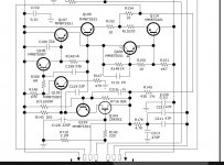
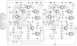
If the right channel works well, you can compare the left and right channels to debug the problem. For starters, could you measure the DC voltages (with a multimeter) at the following locations (see figure):
A) Gate of Q104
B) Source of Q104
C) Drain of Q104, which is also the Emitter of Q159
D) Collector of Q159
E) Base of Q159
F) Gate of Q304
G) Source of Q304
H) Drain of Q304, which is also the Emitter of Q359
I) Collector of Q359
J) Base of Q359
Attachments
Ok
A) Gate of Q104. 0v
B) Source of Q104. 9.36v
C) Drain of Q104, which is also the Emitter of Q159. 9.90v
D) Collector of Q159 18.8v
E) Base of Q159. 10.23v
F) Gate of Q304. 0v
G) Source of Q304. 0.42v
H) Drain of Q304, which is also the Emitter of Q359. 7.89v
I) Collector of Q359. 17.66v
J) Base of Q359. 8.11v
OK, two things seem a bit odd to me:
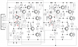
For the left channel, the voltage at node B) is really too high, possibly the output of the amp is stuck-to-high for some reason. For the right channel, I'm surprised that the VBE of Q359 is only 0.22V. But let's focus on the left channel for now. Can you measure the DC at the following nodes as well?
K) Base of Q110
L) Base of 109
M) Output of the discrete amplifier (after R154)
N) Base of Q310
O) Base of 309
P) Output of the discrete amplifier (after R354)
Attachments
K) Base of Q110 16.5v
L) Base of 109. 18.2
M) Output of the discrete amplifier (after R154) 16.8
N) Base of Q310. 0.02v
O) Base of 309. 0.1v
P) Output of the discrete amplifier (after R354.
0.04v
L) Base of 109. 18.2
M) Output of the discrete amplifier (after R154) 16.8
N) Base of Q310. 0.02v
O) Base of 309. 0.1v
P) Output of the discrete amplifier (after R354.
0.04v
Thanks, now it's getting even more interesting 🙂
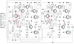
For the left channel, you have a voltage of L) - K) = 18.2 - 16.5 = 1.7V over the VBE multiplier (the circuit around Q108), which makes sense to me. The output voltage at M) of 16.8V is not good (it should be closer to 0V), but it makes sense given the voltages at K) and L). So, it seems the problem happens because K) and L) are not generated correctly. Option 1: first check if R151 is still 4.7kohm and soldered well. If so, option 2: something wrong with the intermediate stages around Q105, Q106, Q107. Please measure DC at the following nodes:
Q) Emitter of Q105
R) Base of Q106
S) Base of Q107
For the right channel, the output voltage (near 0V) is appropriate, but at first sight to me, the voltage over the VBE multiplier of only 80mV (node O minus node N) does not make sense. Oddly enough, the voltage across the VBE multiplier of the left non-working channel seems more logical to me than that of the right channel... Maybe someone can chime in with some ideas here.
Attachments
R151 ok,good soldering
Q) Emitter of Q105. 18.7v
R) Base of Q106. 18.6v
S) Base of Q107 17.5v
Q) Emitter of Q105. 18.7v
R) Base of Q106. 18.6v
S) Base of Q107 17.5v
Last edited:
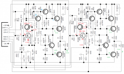
It's a bit strange that the voltage at node S is 17.5V, while all neighboring nodes are above 18V. Anyway, from the results I expect that Q107 may be broken. I would replace this transistor. Optionally, you may also want to replace capacitor C121 on the main board since it has experienced a high voltage (16.8V) with incorrect polarity for some time. If you replace C121, it has to be either an identical component, or otherwise you may want to replace C321 simultaneously for sake of symmetry.
After replacing Q107, check that nodes M and B return to somewhere around 0V where they should be. If the left channel is functional again, I'd compare the VBE drops of the left and right channel (voltage difference from node L to K and from node O to N). If this is still about 1.5V for the left channel and about 0.1V for the right channel, I'd suggest to replace Q308 to see if that fixes that issue.
Looking forward to hearing about your progress.
By the way, Q106 could also be problematic. With the voltages you measured, I think Q107 is the most likely cause of error, but to be safe you could replace Q106/Q107 at the same time.
Attachments
Last edited by a moderator:
That's too bad. Please check the DC at nodes Q, R, S, and L again, to see if they are the same as before, or they have changed. If you did not yet replace Q106, that might be the next thing to try.
Your voltages show about +18 volt on R154 (the output).
Is Q106 turned on or not? What is the B-E voltage across the junction?. (the emitter should be the more positive).
A quick and dirty test is to remove R300 (the 68 ohm). The output should go fully negative when that is done.
Is R151 warm? It should be with that voltage across it. Are you sure it is OK?
- Home
- Amplifiers
- Solid State
- Nad C326BEE left channel pre amp problem