Digital Recreation of a Big PA System

Hi community.

I'm a composer, producer & sound-obsessed "mastering engineer".

I'm developing a particular mastering style where I'm essentially trying to recreate the sound of a big PA system, but at a digital level. Please let me explain:

So my top reference for how I want music to sound is the way I heard it through different systems in a few nightclubs mainly, but also some other speakers I've come across. I always paid attention to the characteristics of the sound and tried to make as many mental notes about it as I could. What I'm trying to do now is to recreate those characteristics as close as possible but within a digital audio workstation, that is by splitting the signal into different bands and filtering/eqing each of them as if they were a subwoofer, woofer, tweeter, etc.

Now, I understand this is something I could never truly recreate because of the simple fact that the sound wouldn't be coming out of that actual speaker. I also understand in the process I'm limited by my own listening environment, in this case KRK Rokit 8 inch studio monitors in a 3x7 metre apartment.

Still, I'm on this obsessive mission to fully design a chain of separate driver emulators and in the process somewhat recreate how it would sound (to me) through this ideal big PA system.

It's driving me insane. Not only because I don't know exactly how these ideal speaker drivers would be set up, their frequency ranges, crossovers, etc. but also because I don't know how to emulate the same filtering they have. I've researched and in some cases guessed regions in the frequency spectrum where the bands may be split, but it's the filtering which is driving me the craziest. The plugins I know and have tried alter the sound in a way I don't want. They are not truly customizable as they don't have the curves you would find in a speaker crossover but most importantly they are not truly clean, they squash the sound, they create pressure instead of liberating it, they just don't do what I want them to do basically...

So my first question to you all is if you know of a software that's designed to create speakers, with filters, ranges, crossovers, etc. but that actually processes an audio signal in the software itself, a digital rendering of what the speaker setup would be later on.

I know this may not make much sense, but it could also be a plugin that you know works in the "same" way a physical crossover in a loudspeaker would, not necessarily one specifically designed for building speakers.

The second question would be if you know of a good list with all the values: frequency ranges, crossover points, slopes, etc. for a big PA system that sounds very clean, very airy, but beautifully full and immersive. A system that blasts the sound at you but never tires your ears, that plays back the bass in your face & yet constantly breathes and feels like a soft cushiony mattress under your feet, that plays back shimmery highs that never sound strident. There's never a buildup of energy, no matter what. This is somewhat the description I can think of for this ideal system I want to recreate.

A third question: recently I came to the conclusion that in these systems I liked some parts of the frequency spectrum felt somewhat removed, especially around 200hz. It's the only way I found to create some of this breathiness I mentioned. Still, limited by the way plugins work I can't seem to find the perfect spot, and thought I'd ask if anyone has any info on this point specifically.

Well, thank you so much for reading & for whatever answers you may have. Also, please let me know if I should post this in another section 🙂

David
Jbl extreme 2 joined in stereo (wired)

Hey folks, its been a very long time since i have been here mainly due to lack of spare time...

Just wanted an honest opinion on something, now when i lived in a house i had a set of bowers and wilkins towers with a rega amp and was very happy with the sound they produced, a change of circumstance now means i happily live on a houseboat.

My question is due to the obvious power and space constraints i had to shed the previous setup and i now own a pair of jbl extreme 2,s which i chose after many reviews and listening to many portable speakers and for the money i felt they had the most natural sound and decent power, you can pair them in stereo if you own two or party mode if you have more (i do have two of the jbl charge 3 also but we will focus on the stereo arrangement of the two bigger ones).

One important thing to note is the extreme 1 is very different in sound and is tuned as a party speaker with high bass emphasis, so if you have only heard this version please dont compare the two when considering my question, the extreme 2 is tuned for accuracy as much as possible and sounds pretty flat to me.

I wanted stereo with lossless so i made a cable to replicate what the wireless stereo mode does (left and right on each speaker driving the LL and RR respectively) and use the line input on each speaker, they are positioned as i would my hifi speakers angled in and a seperation of roughly 6ft and the source is a samsung smart phone playing flac files.

To me i have been very suprised with the fidelity of these little speakers and they have pretty much the same advertised frequency response of the smaller b&w towers i had (50hz-20khz) now im hearing more detail in these speakers than i ever heard in my towers and better bass (cleaner and more precise but maybe not as deep) but the highs and mids now this is where im stunned the detail is so much better than i expected dare i say it much better than my hifi now i want to know if anyone else has heard these and has any critical things to say about them? Are they actually a bluetooth speaker done right or am i just immagining it!

Look forward to some feedback from people with experience of better than the maybe humble b&w towers.

Thanks Mat.

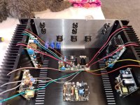
Icepower 6 channel BTL amp build

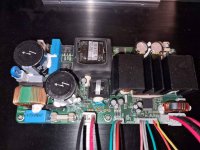
I have my amp ready to wire, and I could use some help, as I have never done this before.

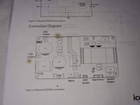
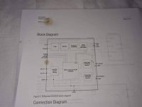
1: How do I know which pin is which on the amp modules... I looked and I do not see any numbering, nor did I see any in the pdf file either. I am using Ghent Audio wiring for the job.

2: What is the best way to route wires? Under the amp modules?

3: Should I twist the wires in groups according to amp modules...ie left hf amp, and left lf amp together?

4: Should all the power leads be run together?

5: On the BTL amps it says to drop the pin to signal ground. What is meant by signal ground?

6: Do I ground the amp modules with a central grounding point or are the brass standoffs sufficient for grounding?

received_1015912672168933.jpgreceived_1004920380024087.jpgreceived_2872409739653427.jpgreceived_2519979374961568.jpgreceived_348587999527455.jpgreceived_2699110800362810.jpgreceived_1042819499502190.jpgreceived_379162143253735.jpg

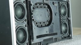
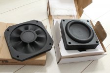
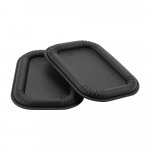
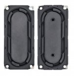
What is the effect of different shapes of the surround of passive radiators

How does the shape of the rubber surround affect the acoustic performance of a passive radiator? What are the benefits over normal design?
I have attached some related images with such passive radiatos.
I assume that it must have advantages over normal forms as well-known brands like Bose implement it in their successful products.

I searched for a while but couldn't find anything on the subject. I also noticed that it only seems to have to do with passive radiators, not speakers.

Attachments

  • PR2.jpg
    PR2.jpg
    133.2 KB · Views: 106
  • PR3.jpg
    PR3.jpg
    294 KB · Views: 95
  • PR4.jpg
    PR4.jpg
    60.2 KB · Views: 108
  • PR1.jpg
    PR1.jpg
    76.4 KB · Views: 96

Sound processing techniques for multi-TV displays?

Just thinking out loud if their are any sound processing techniques relevant for multi-TV displays? I guess this falls in the domain of AV or PA more, maybe for things like security or museums or such.

Of course manually selecting source and adjusting volume is applicable. Wondering if there were other techniques such as cancelling common content, or muting quieter source, or FR tailoring?

Single sided Denoiser PCB design help

:cop: This thread has been merged with posts from here - D-Noizator: a magic active noise canceller to retrofit & upgrade any 317-based V.Reg. :cop:
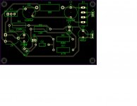
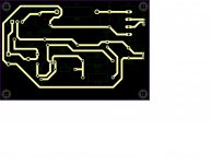
Hi guys, I would be grateful if someone might cast an experienced eye on this PCB layout I have come up with for a single rail LM317 denoiser board. 🙂

It's sized to replace the old PSU board of a preamp I have built, it will be interesting to compare this to the old LM317

***

Hi all, I am trying to put together a PCB for a single polarity LM317 Denoiser and with the help of a few other members I have gotten this far.

The point of the exercise is to be single sided so that it can be etched at home if desired, there are many excellent fab PCB designs available but I haven't found a simple single sided one.

Still to do is to align the resistors vertically if possible, change the type of potentiometer and to make a single PCB but dual mono layout.

Attachments

  • Untitled.jpg
    Untitled.jpg
    226.4 KB · Views: 288
  • Untitled2.jpg
    Untitled2.jpg
    205.9 KB · Views: 280

New amp-project; E83F / 807

Good evening

I am planning e new tube amp project, with E83F and the 807 (5B/250M)

Thought I`d run the E83F at B+ 300V, bias 3,5V, Iq 12,5 mA, RL 15k, and Vg2 at 150V
807 will be at B+ 480V. bias -25V, Iq 50mA, Vg2 at 300V and an 10k load.

Will use the PSU from my former build just to check the circuit, OPT will be Hammond 125ESE. It`s cheap and can be hooked up for various impedances.

Biggest issue will probably be keeping steady Vg2. For the E83F a voltage divider would probably do the trick, it will keep the voltage within a few volts, but the 807 might need VR tubes to avoid burning to much power through a voltage divider.

These tubes are still cheap and it is interesting to dive deeper into Vg2 issues in the circuit.

Any thoughts on the matter?

Marantz 7 clones - vol. potentiometer location?

Hi all,
Got a Music Angel preamp on repair and upgrade.
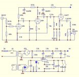
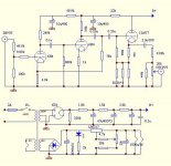
I noticed that the vol pot is placed at the very end of the signal chain ie. between the 2,2mF cathode condensators and the output RCA's (see the first pic).Not a very common procedure,isn't it?....or?
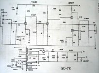
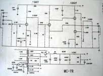
On another Marantz 7 clone I saw (the MingDa MC-7R,pic 2),the volume pot is placed at the beginning (between the input selector and first tube's grid - through a 0,22mF,of course) wich looks like a more appropriate topology.
The tubes in the MA on my bench are 6N2P and 6N1P (not 12A*7 's and the heaters are wired accordingly) .
What are the pros and cons of having the pot at the preamp's output instead of input?
TIA!
Cheers,
S

Attachments

  • Music-Angel-Tube-preamp-pre-Amplifier-Marantz7-circuit-amp-t.jpg
    Music-Angel-Tube-preamp-pre-Amplifier-Marantz7-circuit-amp-t.jpg
    101.6 KB · Views: 545
  • meixing mc7r_schematic.jpg
    meixing mc7r_schematic.jpg
    48.6 KB · Views: 247

Nobsound EL34 DIY with left channel hum

I am a newbie to building amps. I purchased the Nobsound EL34 DIY kit. This is the one with the tubes staggered. I have put it together ok, but the left channel has a bad hum (60Hz).I have swapped everything I can between sides and the hum is there without input. I have retouched some solder joints, twisted wires and shortened some wires to no avail.

My DC voltages look fine but not equal to ones on the schematic. Both sides are very close to each other. Next step I think is to view AC waveforms and record.

I have attached the diagrams I used to build it and am trying to get my photo of the chassis as built uploaded but have run into some kind of issue. Will continue to try. The pdf file is too big.

Any suggestions for getting rid of the left channel hum would be appreciated!

Attachments

A Tube amp without coupling capacitors? Possible?

Ok, I'm going to pull my intellectual pants down and reveal my ignorance for all to see.

"How come they dont" make a tube amplifier, say push pull, DC coupled all the way through, like an IC op-amp is.

It seems way back when Mr Philbrick made an op-amp module using 12AX7s no less and it seems from my limited research the idea of using tubes as DC coupled amplification was never developed out. Certainly not like analogs ICs Have over the past 40 -

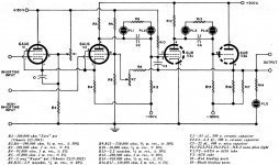
The problem of ridding the circuit of all DC blocking capacitors come down to what else would you use to block the DC? That voltage bias the audio is riding upon from the preceding stage? The only thing I was able to dig up on this is illustrated in the schematic below;

They use a couple of NE-2s to make a floating, 2 pin voltage drop that allows the interstage coupling to land the next stage's grid bias right where it needs to be. I assume that's the only way it could actually work. The pf value capacitor across the Neons suppresses noise, would be my guess?

C'mon. You mean to tell me in all of designing and construction of modern day tube amplification no one has done better than a couple of NE2s as a realizable solution? The Capacitor is just so easy to use! I would think there'd be all kinds of tube based voltage drop circuits, where all some tubes in the amp do is drop voltage between amplification stages.

The reason I'm targeting these capacitors is, IMHO, that the whole music system from the D/A converter output buffer on out is "Capacitor Soup". The audio output from the chip sits up at some positive voltage, so a capacitor is used to block it. That's #1 and I'll save you all by not going through all of 'em to the speaker voicecoils.

Any capacitor that has current going in and out of it in response to music being played through an amplifier / speaker system is imparting its flavor into the recipe. So we have all the high end capacitor products and a lot of knowledge about the various types that sound good. I've always admired how they get rid of one between the input gain stage and the cathodyne...

Does anyone know if such a thing as a non-capacitive coupled tube amp has ever been designed? I mean, the more than two tubes per channel kind. I realize it's a lot more expensive, as such circuits perhaps require regulated and an additional negative supply. But is there a technical (vs financial) reason why this is "never done"?

Let's say an answer is something like "You'd have to have separate, isolated filament windings for all those tubes". So? More glow...

Realizing it's bad to put a DC bias on the output transformer, perhaps being DC coupled all the way through to the output transformer primary isnt so good as well. But, could it be managed reasonably ; instead of blocking a DC offset, detect it like a speaker protection circuit does in a SS amp. Thanks for any discussion on this.

Attachments

  • operational-amplifiers-electronics-world-july-1963-3.jpg
    operational-amplifiers-electronics-world-july-1963-3.jpg
    169.9 KB · Views: 1,897

Marantz 7 clones - vol. potentiometer location?

Hi all,
Got a Music Angel preamp on repair and upgrade.
I noticed that the vol pot is placed at the very end of the signal chain ie. between the 2,2mF cathode condensators and the output RCA's (see the first pic).Not a very common procedure,isn't it?....or?
On another Marantz 7 clone I saw (the MingDa MC-7R,pic 2),the volume pot is placed at the beginning (between the input selector and first tube's grid - through a 0,22mF,of course) wich looks like a more appropriate topology.
The tubes in the MA on my bench are 6N2P and 6N1P (not 12A*7 's and the heaters are wired accordingly) .
What are the pros and cons of having the pot at the preamp's output instead of input?
TIA!
Cheers,
S

Attachments

  • Music-Angel-Tube-preamp-pre-Amplifier-Marantz7-circuit-amp-t.jpg
    Music-Angel-Tube-preamp-pre-Amplifier-Marantz7-circuit-amp-t.jpg
    101.6 KB · Views: 399
  • meixing mc7r_schematic.jpg
    meixing mc7r_schematic.jpg
    48.6 KB · Views: 219

Power amp module ->Guitar amp???

Hello!
I have a low experience with guitar amps. Specifically, I know that the amp is a combination of a power source, preamp, effect loop, power amp and the speaker.

I found a power amp module and thought to build an amplifier with it.


My plan is this:
-For power source I was thinking to use a laptop adapter (there are a lot of 18 Volt with max 5 A- 90 watt)

-The power amp module I found is this
Dc 12V-24V TPA3118 BTL 60W Mono Digital Audio Power Amplifier Board Amp Module A | eBay

-For a preamp I was thinking a tl072 based preamp with the features:
-pregain,

-tonestack-maybe a marshall like tonestack
-followed by a tube screamer clipping stage

-a unity gain buffer followed by a volume control


Is there a way that this concept will fail completely?


edit: Rephrasing the question "Is there a possibility that this project will work at all?"

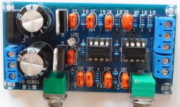
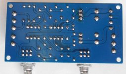
Budget active subwoofer lowpass #2, buy, eval, mod

I was looking again for another low cost subwoofer bandpass board. I've already modified one and I was about to modify it again when I decided to see what else was available and roll the dice another time. My previous one is at Budget active subwoofer lowpass, buy, eval, mod and required substantial mods and I'm not entirely satisfied with it.

I noticed a board that had stereo pots on it 🙂. Adjusting a 2nd order filter requires a stereo pot because 2 resistor values need to change at the same time. It also had enough caps to probably be a higher order bandpass and it's <$10 CDN delivered. Zero documentation is a standard for these products.

Attachments

  • DSCN7563r.jpg
    DSCN7563r.jpg
    356 KB · Views: 375
  • DSCN7562r.jpg
    DSCN7562r.jpg
    225.5 KB · Views: 390
  • Like
Reactions: techgeek

Threshold model 4000 high input sensitivity

Hello! Finally my Threshold is back totally fresh. I use this amp to drive my horn drivers and tweeters of my JBL 4560 speaker system and a Crown PSA2 just for the woofers. I know that 250w just to drive a pair of horn drivers and tweeters are many but i don't think that could cause any issue. Although i got a problem with the high input sensitivity of this amp. Because of that i got extended hiss on my horns and also is not easy to match from the electronic crossover the sensitivity of the 2 amps. A small move on thw volume of my preamp and the gain of the threshold goes to the sky 😛 Is there any way to reduce the input sensitivity of this amplifier? Best regards !!!

Speaker compatibility

Hi all. I wanted to know your opinions. I have a B&C DE900 16 ohm
treble driver, mounted on B&C ME90 horn.
I am thinking of combining it with a 10 inch speaker, to
build a 2-way direct radiation speaker. I am looking at 2 models of the RCF brand. They are the RCF MB10N251 or the RCF MB10N305 I would like to know if these speakers seem compatible
with the B&C DE900 controller at the breaking point.
The system will be bi-amplified and actively processed. Also to say that the system will be ridden in bass with a
subwoofer of 15 A greeting.

Here i let you the links of the speakers:
B&C Speakers
Product Detail - RCF

Upgrading B&W 683 crossover

I recently acquired a pair of these and like them, a lot🙂. They replaced many far more expensive floorstanders in recent years that were without question more refined but ultimately nowhere near as enjoyable to listen to.
While the 683s are not perfect by any means either, I think I`ll hang on to them for a while which has me wondering if a crossover component upgrade may be a cost effective tweak that`ll bring their performance up a notch.

I have read on a European forum that these speakers respond quite favorably to better crossover components.
My biggest "gripe" with these is that I find the top end a little too polite, lacking some bite and sparkle that I know exists.
The same could be said to a lesser degree about the FST midrange driver but I`m nitpicking on both accounts here.

I`m considering replacing the tweeter capacitors to one of these two:

Solen AGM470 - Silver Metallized Polypropylene Capacitors
or
Audyn KP SN Capacitor, 4.70mF 160Vdc. 2% Tolerance, Axial Lead

These are the two that are readily available and reasonably priced but I`d be open to other suggestions within the price range.

I`m also considering replacing the two generic resistors in the midrange band pass filter to some non inductive types while in there.
Depending on the results achieved by the HPF cap change, I may be tempted to replace the two midrange and woofer caps at a later point as they are of greater value and expense.
Your thoughts?

Attachments

  • HPF.JPG
    HPF.JPG
    68.9 KB · Views: 713
  • LPF.JPG
    LPF.JPG
    60.9 KB · Views: 1,099

Help me mod/upgrade my Swans 6.1

I've had these speakers for a few years and while I'm quite happy with them, I always felt they could be better, especially the top end.

Bass is good, not amazing but good, mids are OK (lacking a bit of articulation and clarity), trebles are OK but a bit harsh, fatiguing if volume is turned up. Also, I'd like to have more air.

The speakers are:
1x HiVi F6 6" Bass/Midrange
1x HiVi TN28 Fabric Dome Tweeter
2x HiVi M8a 8" Aluminum/Magnesium Woofer
An externally hosted image should be here but it was not working when we last tested it.


The speakers are bi-wired and connected to a Micromega PW400 amp, cables are 10AWG BJC.

It's not easy to find better replacements for the top mount tweeters... so I'm considering several options:

First, I can't seem to find a way to move the pods. They seem to be fused to the cabinet somehow... Doesn't look like I'd be able to remove the tweeters either so I'll have to find a way to yank them out of the cabs. Once that's done:

1. Find other similar pods and install better tweeters in them (original specs are 1 1/8 soft dome, 6 Ohms, 40W, 88db, 2K/20K).
HELP: Any tweeter suggestions? Where can I find one that would fit these pods? Can I use 4 or 8 ohms instead of 6?

OR
2. Build/Buy a small cab or open baffle and use a better tweeter.
HELP: If I do this, I'm thinking of getting a ribbon tweeter. Any suggestions?

OR
3. Change the midwoofer (6 1/2, 8 Ohms, 45W, 88db, 42/4K) to a midrange driver (something like 100/12K) and use a Super Tweeter on top.
HELP: Would I need to change the crossovers? What Super tweeter would you recommend? Fostex?

OR
4. ???

The crossovers look simple... 2 coils, 1 47uf bipolar cap and 1 3.3Ohms 5W resistor. I was thinking about upgrading the cap and resistor. Can't hurt...

What do you guys think?

I've built several amps and a few other things but I lack experience with speaker builds/mods...


Thanks for your help and suggestions!!

Phono pre power supply and ground question

I'm working a design for an all op-amp MM phono stage and I'm going to use a Salas shunt regulator for the +/0/- power supply. Using op-amps outside of guitar effects pedals and shunt power supplies with a negative rail are new to me so I have a couple of questions. Forgive my ignorance if the answers seem obvious.

Where will the turntable and the preamp chassis ground? The 0V audio ground or the V negative rail?

According to my math my circuit will require less than 200mA. Is this enough load to keep the shunt regulator operating properly?

Thanks for your help.

Realistic 10 bands Equalizer type 31-9081

Hi guys, i hope you can help me.

I have a Realistic 10 bands Equalizer type 31-9081.

!Bh8P(bwBGk~$(KGrHqMH-DcEsNkvQYUhBLLv,S58p!~~_12.JPG


An externally hosted image should be here but it was not working when we last tested it.


I have this Equalizer for almost 20 years, but now there where some problems with it. When i put it on, on the first minute in a cold situation it sounds not very well, so i will replace all capacitors with new good one from Panasonic or Nichicon.

Are there people who have any service manual for me.🙂

I will also change the 3 op-amps njm4558D with OPA2134. But the biggest problem is, It sounds noisy when there is no sound. I think the power supply is a little bit weak. Do you have any sugestions for me to make this Equalizer sounds beatiful with a minimum of noise and good components.

Regards Rick...😀

SEAS Thor xover Q/tweak suggestion

Need some help in making the decision on swapping out a cap in my new SEAS Thor xovers.
Spoke with madisound, they had no answer to my Q.
Here is the schematic for the Thors, along with some pics of the new xovers
http://www.seas.no/images/stories/diykits/pdfdataheet/filter_thor_odin.pdf

Attachments

  • IMG_1495.jpg
    IMG_1495.jpg
    739.2 KB · Views: 103
  • IMG_1496.jpg
    IMG_1496.jpg
    795.4 KB · Views: 97
  • IMG_1497.jpg
    IMG_1497.jpg
    515.2 KB · Views: 92
  • IMG_1498.jpg
    IMG_1498.jpg
    463.3 KB · Views: 86

Raspberry i2s Output for MiniDsp for Dummies :D

Hi,


forgive my stupid- and lazyness to work through all the articles on the web,...but i am still not able to find any usefull information of how it is possible or IF is even possible to just use an raspberry with or without any dac, to have this tiny board given audio through i2s to an minidsp.


In my understanding there is only one issue which stands in the way, and that would be te need for the minidsp a "clocked" i2s input?! But please tell me if i am heading in a wrong direction.


So is there any dac which one could simply put on an raspberry pi via gpio which gives clocked i2s audio which than could be put into an minidsp balanced or 2x4 (not hd).


The Idea behind all this is that i've got these two boards lying around and simply want to put them to good use. I know that there is the minidigi option from minidsp which i could put on the balanced for example and than put an spdif dac on my raspb take an lwl...boring.
In my mind it sounds way to complicated to have two extra boards (minidigi and spdif dac for the rasberry pi) just to use the i2s for the balanced. all and all for the same price which would cost a minidsp hd which already has spdif input.


From all the search i've done until now, there is a certain kind of feeling"betrayed" (dont get me wrong :-D) from minidsp, that they've got these i2s inputs which in general nobody could use the easy way, for builiding an really cheap "streaming crossover".

Ok yeah please buy the shd, there you go...🙄.


So please tell me, am i stupid/not able to find the right post/link how to do this without spending unnecesarry money, buy just using grey cells in my head?! or is the only way through rasp+dac+digi option on the dsp board?


Would be nice to get some reply.


Regards Swany

Apt Holman preamplifier questions

Hello Guys,
My Apt Holman preamplifier has lost left channel phono input. So I'll have to open it to solve this problem.
In the mean time I've read a lot about this device and compiled some information in order to repair it and improve it a bit if I can.
I therefore have a lot of questions and i would be delighted and thankful to get answer from here.
1) the FET input transistors of the phono preamp are selected for low noise. how do you do that ? What kind of equipment you need to do this ?
2) As the fault is in the phono stage, I've searched for availability of parts. The 2N5484 seems to have vanished and it seems there is an SMD replacement available (MMBF5484). The 2N5458 seems to be available and one of the usual suspects (Farnell) suggest J109 as a replacement, but Mouser seems to have the correct original one. What do you think of that ?
3) on one thread, someone suggest to replace the power regulators which seems to age bad. Should I use the same reference or replace them with better parts ?
4) The original Op Amp are (as far as i can tell) fine. Should I leave them be or replace them ? And if i replace them, is it clever to put sockets for them ?
And last but not least, the power supply. In France we have switched to 240V for mains. The transformer is made for 220 V. Should I find a replacement to have the voltage correct (my mains is at 237V and sometimes above 240 as I'm near the substation) ? If I should change the transformer, what should I look for ?
As you see, a lot of questions, and I thank you to have read them all !
Thank you in advance for your answers !

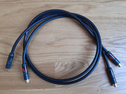
"REGA couple" clone: Klotz AC110 & Neutrik NF2C-B Hifi-Stereo Cinch, Cable aprox. 1m

"REGA couple" clone: Klotz AC110 & Neutrik NF2C-B Hifi-Stereo Cinch, Cable aprox. 1m

These Klotz & Neutrik 1m Dual Phono Cable is the perfect cable for wherever maximum sound fidelity is Key. The AC110 has a brilliant thick sturdy jacket, the double screening and a thick foam PE insulation of the robust conductor. The Neutrik is a high quality connector that will last you a lifetime due to their precisely machined parts to maintain Neutrik's quality standards.


cable no.: AC110
cond. construction: stranded bare copper, 7 x 0.20 mm
cond. cross section: 0.22 mm2
overall diameter: 6.9 mm
conductor resistance: < 85 Ω/km
cond. / shield: 65 pF/m
insulation resistance: > 1 GΩ x km

Connector: Cinch (Neutrik NF2C-B)
Connection first to ground, then to signal path, when unplugging first signal path, then ground is disconnected
Precisely milled parts
Unique Neutrik collet chuck strain relief
Gold-plated contacts

25.- EUR plus shipping within EU (& GB)

And as always:
Private sale, warranty and exchange excluded.

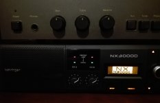
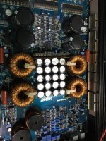
Bheringer series NX LEDs do not work

Well here I am, I bought the NX3000D and I'm already sorry, and not just because of the loud fan noise .......
From the first time I turned it on I noticed strange behavior in the signal indicator LEDs.
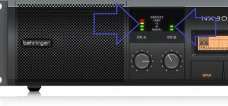
Some never turn on! Check out the photos of Bheringer and my amp.
In my case, it only turns on the green light at the bottom and the red light at the top.
The intermediate lights do not act at any time, (- 6 Db green and - 3Db yellow) I have tried varying the input signal with different voltage sources, but it does not make any difference.

No matter where the knobs are located, only the lower green light will turn on, and without intermediate steps, the upper red limit light ...
I wrote to Bheringer for technical support and they replied that "this is normal". That simple ....
So why are they on the amp ?
I have written again to ask for an explanation
more detailed and technical as possible. But while I wait for their response, I would like to know the opinions of the users of the NX series here.
What am I not understanding ?

Attachments

  • IMG_20200818_193345.jpg
    IMG_20200818_193345.jpg
    688.1 KB · Views: 185
  • NX3000D_P0CHW_Front_XL.jpg
    NX3000D_P0CHW_Front_XL.jpg
    143.4 KB · Views: 192

American Bass VFL-500.1

Amp powers up and plays audio perfectly .

Problem is I get a static sound through the output .

From rca shield ground to amps main ground terminal I get 1k ohm

I get 1 volt of DC voltage on the rca shield grounds using amps ground terminal as reference

I get 2 volts of DC voltage on the heatsink also black probe on amps ground terminal red probe on heatsink


Any ideas ?

Attachments

  • 15FC38FE-6749-46F1-BF5F-43654073B444.jpg
    15FC38FE-6749-46F1-BF5F-43654073B444.jpg
    1 MB · Views: 140
  • 91E82A3B-B31E-4F91-B396-18D825B3307F.jpg
    91E82A3B-B31E-4F91-B396-18D825B3307F.jpg
    1 MB · Views: 117

Anyone have order issues with Arrow Electronics?

I'm curious if anyone has had issues or can explain my experience.

Last week I placed an order with Arrow, one of the items was IRF1404PBF's. I'm fairly confident I ordered 26 but only 18 showed up today. I double checked my order confirmation emails and they show 18 qty. for $33.95. The product page on their website shows 18 @ $22.82 and 26 @ $32.96. I opted for free shipping since I was in no rush and the tariff was 0.18 for my entire order so neither of those explain the discrepancy.

Yes, I've already submitted a support ticket but I'm curious if anyone has any insight as to what's going on. I'm thinking I need to go back to Mouser from now on.

Parasound HCA 1000A Overload Indicator

Hey all, I have a Parasound HCA1000A here (schematic attached) and the right channel overload LED is permanently illuminated (amp powered on of course), even with no signal present. The left channel does not have this problem. I did some troubleshooting and found that both Q003 (right channel) and Q004(left channel) both have roughly 15 volts on the base and emitter, while Q0004 has 0V on the collector but Q003 has 5 volts on the collector which is dropped to 1.8V by R008 and is enough to turn on the LED. The surrounding components seemed to be fine so I figured Q003 had to be the culprit. However, after replacing it with another general purpose PNP transistor there is no change in the scenario. Anybody have an idea what might be going on?

J.

Attachments

The fix

Amps powers up has rail and regulated voltage but no output.
After about 40 sec it will cycle in and out of protect a few times.While that is happening i get output in between.


Looking at the outputs pins on the driver ICs i don't see any signal even when there is output for the few seconds.


Any suggestions?

Attachments

  • fix1.jpg
    fix1.jpg
    145.8 KB · Views: 140
  • fix2.jpg
    fix2.jpg
    93 KB · Views: 126
  • fix3.jpg
    fix3.jpg
    118.7 KB · Views: 127

Question for VituixCAD users re - skipping vertical polar measurements

I wanted to know whether it would be okay to skip vertical measurements for drivers if I am mainly concerned about performance in a small listening area (i.e., vertical = +/- 5deg, horizontal = +/-15).

Specifically, I have a question in regards to the below excerpt of Vituixcad instructions:

" Measurement of vertical plane can be skipped if the driver and possible wave guide/horn are circular i.e. directivity in vertical plane is equal to horizontal plane. Skipping of vertical plane could cause small hump (< 1 dB) to power response at diffraction peak frequency if baffle height is longer than width. In that case sound balancing should be weighted by axial response around diffraction peak frequency (wave length = baffle width"

I'm designing a small 2-way using JBL 2226H 15" driver and 90Hx45V Horn.

Not sure if I'm interpreting the paragraph correctly, but is it saying that a driver's vertical radiation pattern is assumed to equal to its horizontal radiation pattern when vertical measurements are not taken/provide/uploaded into VituixCad. In which case, the JBL 2226H H-radiation will reasonably match V-radiation, but the Horn's V-radiation will not match H-radiation.

If my design axis is the center of the horn tweeter, then it should not be a material issue - correct?

Also - if my design axis it the tweeter - would it make sense to take both the horn-tweeter measurements and the JBL 2226H measurements at the tweeter axis, and indicate 0x,0y,0z coordinates for both the horn-tweeter and the JBL2226H woofer.

Portable Garden Sub (Cheap).

I'm trying to re-purpose some spares to make a portable 2.1 system for outdoor use. It's only for barbecues so there's no desire to impact the Richter scale.

The cabinet is constructed of 15mm MDF and measures 360mm (W) x 245mm (H) x 245mm (D). (15l).

Each of the side aspects contains a 6.5" driver: Fs 40Hz, Q 0.5 Xmax 6mm.

The front elevation hosts two cylindrical ports 40mm in diameter and 125mm deep (flared both ends).

Sealed inside the cabinet is a Dell 19.5v (65w) PSU and a TPA3116D2 amplifier.

Before I start screwing and gluing . . . is there anything that needs to be tweaked?

Please identify crossover (British)?

I bought this thinking it was 3 way, but closer inspection would have told me otherwise ;-)

However, I can't identify it's origin, and therefore what drivers would suit.

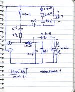
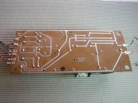
I have traced the circuit, but it seems a little odd to me - very busy, especially around the tweeter - but then again i may have made an error.😀

Thank you for looking

Attachments

  • crossover01.jpg
    crossover01.jpg
    240.3 KB · Views: 230
  • IMG_0201.JPG
    IMG_0201.JPG
    309 KB · Views: 210
  • IMG_0202.JPG
    IMG_0202.JPG
    387.5 KB · Views: 196

I dont believe it

Built up a USB PC scope interface pcb by hand.
A couple of the IC's are SOIC SMD 0.127mm pitch so a little care is needed.
Sometimes get a short and sometimes a dry joint so I now run soldering up and down pins a couple of times to be sure.
Shorts are found with magnifying glass and undone.

As its first power up microcontroller requires programming.
So plug programmer into plug on pcb and plug in USB cable for power and comms.

Micro wont program there is an error.
So re-solder pins using flux and solder on tip of iron.
Still wont program so I check for faults on pcb and everything looks good.
So think micro must be faulty.
Hot air gun to unsolder it.
Fit new micro and hey presto, still not working.
Starting to tear hair out now, well what's left.
I then turn around and catch USB cable with my foot.
Noticed its not plugged in PC end.
!"£$%^^&£"$£$"£$£$£
Plug in USB cable to PC and scope works first time.

FS: FET Audio FDA-1B DAC

For sale fully assembled FDA-1B DAC kit designed by Spencer Cheung of FETAUDIO.

More info here:
New FDA-1B Full Balance PCM1794A DIY DAC kit << FET Audio | Hi-End Audio Projects

Manual:
http://www.fetaudio.com/wp-content/uploads/2012/04/FDA-1B-DAC-Manual_r1.pdf

No trafo included in the price.

Asking $100 shipped to lower states.

Thanks for looking

Attachments

  • 20180921_185723.jpg
    20180921_185723.jpg
    593.4 KB · Views: 820
  • 20180921_191039.jpg
    20180921_191039.jpg
    454.1 KB · Views: 801

FS resistors capacitors diodes transistors

Ive got too much stock of certain components, so instead of letting this stuff sit in storage indefinitely i have decided to offer op my surplus components here. Its a mix of stuff and i will post it in the next day or two.


Most lots are €1 each with some exceptions.


I have a shoebox full of 150R 5W wirewounds, im not gonna use that in a lifetime, so if anyone wants to take some off my hands😉


I also have lots of nice Beyschlag metal film resistors. I have the bags available for cheap, and i can also supply the following values from my personal stock in limited quantities. 0309/1K0 2K0 5K1 8K2 13K 22K.

Tubes for sales - 71aST, 45ST, 26ST

Tubes for sale!

5 x type 45,St 95ea. No match pairs, different brands, purchased from Antique Supply(white box) (all Sold)
6 x 7236. 95ea. NOS in Original Box, No match pairs (Lowered price $80ea or All 6x For $450)
2 x WE 412a. 70ea. NOS in Original Box, No Match pairs
2 x 6754. 90ea. NOS in Original Box , No Match pairs
6 x 71a. 50ea. NOS in Original Box, No Match pairs (all Sold)
6 x Vt 25. 60ea. NOS in Original Box, No Match pairs (all Sold)
4 x type 26,St 40ea. NOS in Original Box, Westinghouse Brand(all Sold)
2 x Bendix 6877 90ea. NOS Red Bank
8 x type 30,St $20ea NOS in Original Box, No match pairs
All the above tubes are plus shipping.

LJM L12 Stereo amp board

I need some help. I bought two of these boards a couple of years and have been using them as stereo power amps. I have previously bridged 2 SS amps using boards obtained after an article in the magazine Everyday Practical Electronics, now EPE.

To power the module (LM833 based) you need a split rail supply and it is suggested that you piggy back the amps own supply. This has been fine in the working pair.

I have hacked into the supply of one of L12 boards and perhaps unwisely piggy backed the bridge rectifier and not the caps attached to it. All was well when using the light bulb limiter and so I gave it full power. It played for 20s and then started to die and a very small amount of the magic smoke appeared from the area near the +leg of the rectifier. I removed the rectifier and inserted another, but it would not fire up (bulb full brightness and no LED lit on amp board. The only other component in the area of "the smoke" is a 1uf tantalum bead cap which looked fine. I removed it and tested it and it is within spec. All other components look fine. Anyone have any ideas?

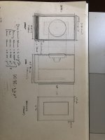
Help finalising enclosure design (Dayton RSS315HF-4)

Hi all,

So am in (hopefully) the final stages of designing my first enclosure, I decided to go for the Dayton Audio RSS315HF-4 12" driver. Using WiniSD I have worked out that the internal volume will be 3.7ft^3 tuned to 24Hz.

I just wanted to post the plans on here before sending them off to get the wood cut to make sure that it all looks ok, I also have a few questions.

Firstly, does the bracing look strong enough? was just going to have that one central panel but could add in a second one if needed.

Secondly, is a crossover needed if it will just be on its own amplifier channel (which has DSP) and if so will this need to be a band pass filter? I have struggled to find information on what values of capacitors/inductors I would need to use. If anyone could point me in the right direction that would be amazing.

Sorry for the hand drawings do not have access to design software. are there any free softwares that are good for 2D design? would be helpful to draw out the individual parts on there for accuracy.

I think I've attached all relevant graphs.

Any other tips are very welcome, thanks in advance

P.S. am aware that this driver is better in a sealed enclosure but ported suits me better for what ill be using it for.

Attachments

  • Screenshot (38).png
    Screenshot (38).png
    150.8 KB · Views: 206
  • Screenshot (39).png
    Screenshot (39).png
    142.7 KB · Views: 187
  • Screenshot (40).png
    Screenshot (40).png
    148.5 KB · Views: 186
  • Screenshot (41).png
    Screenshot (41).png
    142.8 KB · Views: 181
  • Screenshot (42).png
    Screenshot (42).png
    144.6 KB · Views: 202
  • IMG_7902 copy.jpg
    IMG_7902 copy.jpg
    461.6 KB · Views: 140

External Soft Start for Class A Amp

OK, so I watched this video and a few things came to mind (ahem...you will see what mean...now why did they go and do that?)

Raymond Innovations - A10 Universal Soft Starter demonstration. - YouTube

A plug in, external Soft Start...

So I can just put a CL-60 in an external box (mains between Class A amp and wall) or just put the CL-60 inside the wall receptacle, no?

Audio Research D160

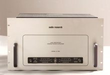
Hi,

I can buy a Audio Research D160 but I can't find very much information on this AR tube amplifier.
I did consult the ARCDB pages and the Stereophile review of the D160B but that's about it.
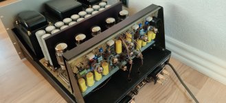
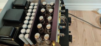
Does anybody know more in depth about possible problems, weak points or anything else about this amplifier.
One problem seems to be those 20 Mepco/Electra Series 3187 snapin 5 pin filtercaps that are new unobtainable themselves and hard to find any good substitutes for.

Tube biasing is made easy at the back and another nice touch are the LED output meters so you see more or less the power needed to drive your speaker.

Thanks in advance,

Robert
https://www.diyaudio.com/forums/attachment.php?attachmentid=862616&stc=1&d=1595422881
https://www.diyaudio.com/forums/attachment.php?attachmentid=862620&stc=1&d=1595422881
https://www.diyaudio.com/forums/att...el-dudeks-upupa-epops-lm4780-amp-dscn0503-jpg
https://www.diyaudio.com/forums/att...862618&stc=1&d=15954228819&stc=1&d=1595422881

Attachments

  • Audio Reseach D160 pic2.jpg
    Audio Reseach D160 pic2.jpg
    289.4 KB · Views: 375
  • Audio Research D160 inside 2.jpg
    Audio Research D160 inside 2.jpg
    501.9 KB · Views: 445
  • Audio Research D160 inside 1.jpg
    Audio Research D160 inside 1.jpg
    639.8 KB · Views: 311
  • Audio Research D160 back.jpg
    Audio Research D160 back.jpg
    650.4 KB · Views: 372

Tone Control Modification

I've decided to modify the tone control of my receiver; SAE TWO R9. The schemetics is on attached. The specs indicates tone control operates at 100 and 10kHz for bass and treble, respectively. I wish to modify the tone control to operate at 50 and 15kHz instead. Could anyone help to tell me which parts should I modify? Another question, if the modification was done on tone controls, will the loudness operation also be affected? (From boosting at 100/10kHz to 50/15kHz) Thank you in advance

Attachments

Motorola SC99659P for Rotel RCD 855 CD player fix

Gents hi,

Hope someone more expert than myself can help please🙂

My Rotel RCD 855 the display does not light up nor buttons respond when powered up anymore.

I have checked internally and to cut a long story short when I unplug the connector at location E106 next to the Motorola SC99659P 40 pin chip, the display lights up all segments.

That proves to me the fluro display itself and board are ok as its receiving power.

I suspect the Motorola SC99659P which has three connections to E106 connector is shorting out internally.

My questions is does anyone have an SC99659P they pulled out of a Philips based TDA1541A player they can sell me to try?

Thanks in advance and all thoughts greatly welcomed.

Cheers!

Lee

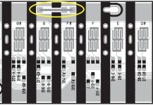
What is the mysterious 'strip' on keybeds of digital pianos

Hi guys, I have always wondered what the purpose of the mysterious strip found on the keybeds of digital pianos are. There seems to be a carbon line in the middle and soldered at both ends and in the middle. Doesn't seem to be connected to anything important :S and nothing is placed on top it when the keybed is assembled.
Thanks in advance.

Attachments

  • Strip2.png
    Strip2.png
    71.8 KB · Views: 153

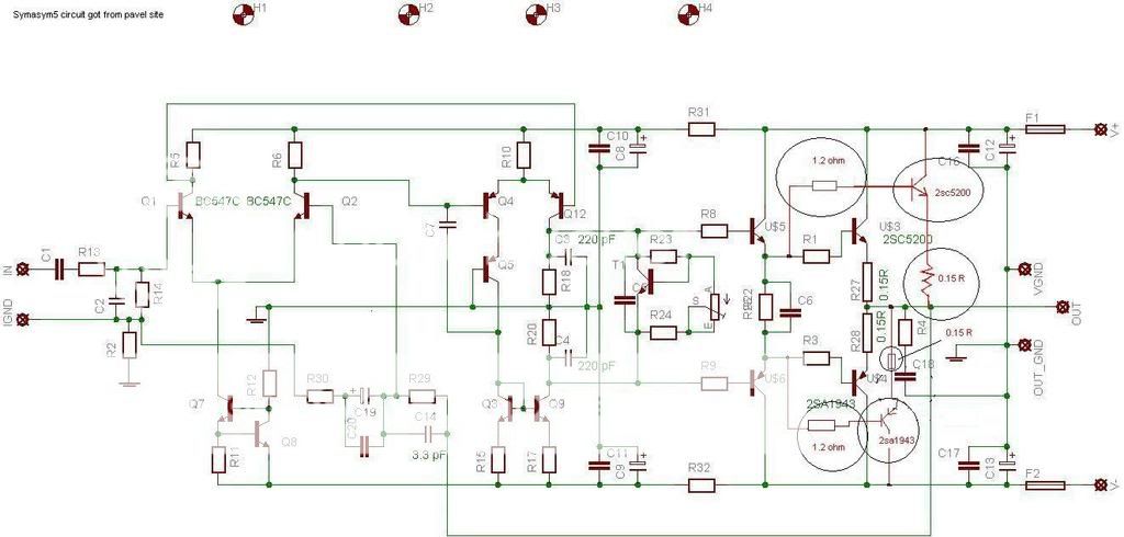
Symasym5 modifid circuit

hi, i am not good in electronics as all of you. i need help for this circuit design. at first i got it from Symasym5 then went to pavel site to have this modofied circuit design. i have build it. now i have modified by adding one more power transistor 2sc5200 and 2sa1943. i circled the design. do you think it is correct way to adding power transistor in parallel? i have posted the pic.


thank you.

myversion.jpg

Amp grounds

hi,

Anyone help. I have two amplifiers and i have some ground noise. Question is can i use two seperate ground points either side of the car as the current ground is not good enough, so i need to move it.

The mixed reviews say to use the same ground, but where there positioned i wont be able two unless one ground wire is longer than 18 inches

Many thanks,

SainSmart 6N3 pre for Pass ACA

Hesitate to ask for fear of being flamed, but…

I’m building Pass ACA mono blocks to mate w/ some of the single full range driver speakers I have built, so I need a pre. I use a passive pre w/ the Dynakitparts ST-35 I built a few tears ago, but the input impedance of the ACA seems too low for this approach.

I’m not a hard-core electronics guy like most of you, nor do I have lots of cash for this project. So I want to do something quick dirty to get up & running. There are some folks on another site who seem to like the SainSmart 6N3, so I ordered one. (see: http://www.amazon.com/SainSmart-Ass...qid=1463360213&sr=8-1&keywords=sain+smart+6n3 ) I also picked up some NOS GE JAN 5670w tubes to use in place of the stock Chinese tubes.

My concern is that the transformer is labeled as 110 v. input. My wall sockets measure 124 v. (most of the time). Output from the transformer measures correspondingly more than the 6.3 v. for the heaters and 170 v. for the plates.

What to do?
1) Use it ‘as is’ & burn through tubes?
2) buy a new transformer? buy a step down transformer? (but I have no clue what to buy)

Any advice would be appreciated!

Thanks, Jim

My hobby room sale - amps, speakers, heatsinks ,parts, enclosures...(adding slowly).

I am cleaning out my hobby room, and need to clear out the shelves for new projects. I will be adding additional items in the next few days. Feel free to contact me for more information or photos.

1. Leach Amp, two modules, unfinished & untested, Panasonic FC, Wima, silver mica... 20€ SOLD!
2. PSU with speaker protection. Never used and untested. 15€ SOLD!
3. Daytona Sound Exciter NXT, just tested. 10€ for pair.
4. DC ampere and volt meter, US made. 8€
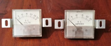
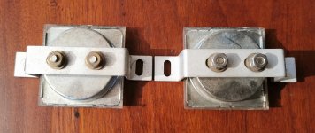
5. 6x heatsink - 10x7,2x12cm HWD, one is black anodized, 1,2kg each. 40€ for all. UPDATED to 15.1
6. 1 x heatsink - 16,4x16,9x8,8 HWD, 3kg. 20€
7. 4x spikes - gold color, 32mm diametr. 6€ for all.
8. 2x Leach Amp PCB - 10€ SOLD!
9. 2x Hifisonix Multiplier Cap PSU PCB - 20€ SOLD!
10. Hifisonix 28W Class A CFA Power Amp - 2x kx Ampifier + PSU - 20€ SOLD!
11. 4x NJW3281G and 4x NJW1302G - new from Mouser - 25€
12. 2x OPA549T Operational Amplifier - 20€
13. 2x 2SC5200 & 2x 2SA1943 Toshiba - soldered but newer used - source Farnell - 10€
14. 2x 2SC5200 & 2x 2SA1943 Toshiba - new - source Farnell - 15€
15. Dual Power Supply PCB - 5€ (8 for pair)
16.1 2x OPA541AM - just tested - 10€ for pair UPDATED to 16.1 SOLD!
17. 2x heatsink 250x76x33mm - 0,72kg - 15€ pair SOLD!
17. 2x heatsink 130x70x38 - for TO-3 transistirs - 0,38kg - 5€ pair
18. Superphon SP100 line buffer PCBs - 2x buffer and power supply - 10€ SOLD!
19. 2x speaker protection - newer used - untested - 4€
20. 2x Focal 7K415 - original box - new - 120€ pair
15.1 12x heatsink - 10x7,2x12cm HWD, one is black anodized, 1,2kg each. 60€ for all.

Plus shipping. You can pay with Paypal. Selling as is.

Attachments

  • 2020-05-09 16.34.02.jpg
    2020-05-09 16.34.02.jpg
    258.5 KB · Views: 1,781
  • 2020-05-09 16.34.21.jpg
    2020-05-09 16.34.21.jpg
    277.9 KB · Views: 1,778
  • 2020-05-09 16.34.43.jpg
    2020-05-09 16.34.43.jpg
    251.2 KB · Views: 1,753
  • 2020-05-09 16.36.06.jpg
    2020-05-09 16.36.06.jpg
    261.3 KB · Views: 1,753
  • 2020-05-09 16.36.15.jpg
    2020-05-09 16.36.15.jpg
    256.3 KB · Views: 1,729
  • 2020-05-09 16.36.32.jpg
    2020-05-09 16.36.32.jpg
    267.7 KB · Views: 322
  • 2020-05-09 16.38.39.jpg
    2020-05-09 16.38.39.jpg
    358 KB · Views: 331
  • 2020-05-09 16.38.53.jpg
    2020-05-09 16.38.53.jpg
    582 KB · Views: 289
  • 2020-05-09 16.48.29.jpg
    2020-05-09 16.48.29.jpg
    173.9 KB · Views: 272
  • 2020-05-09 16.48.40.jpg
    2020-05-09 16.48.40.jpg
    198.5 KB · Views: 242

FS: Hypex 2x UCD400ST amp with linear power supply.

For sale: 2x Hypex UCD400ST amp with linear power supply.

XLR inputs.
Power supply: 600VA with additional 12V/2A output, dual bridge, 4x Nippon Chemi-Con 10000uF
Aluminum case.

200€ plus shipping (EU only).

Attachments

  • 2020-06-21 09.29.14.jpg
    2020-06-21 09.29.14.jpg
    233.6 KB · Views: 678
  • 2020-06-21 09.29.38.jpg
    2020-06-21 09.29.38.jpg
    463.4 KB · Views: 678
  • 2020-06-21 09.29.56.jpg
    2020-06-21 09.29.56.jpg
    362 KB · Views: 663
  • 2020-06-21 09.30.18.jpg
    2020-06-21 09.30.18.jpg
    369.2 KB · Views: 675

MEGA AMP...150 pounder for P/U in CT

Anyone want a huge rare amp that needs some work?


It's an NRG model A201S. 200 WP Class A stereophonic amp. Weighs somewhere around 150 pound. The toridal transformer is the size of a wheel of Wisconsin Cheddae


Google will give you some info.


This has sat for 14 years in a climate controlled storage room since being un-exported back to this country from London. Wired for 220v. An easy conversion back to 110V? I am not a tech.


Made in Walled Lake Michigan. This amp was sent to England, then brought back here by the Brit owner...and then it sat in Scarsdale, NY until today when I picked it up as part of a large trade.


One of the photos show a Will Vincent Dynaco MKIV sitting on tip, ust for a sense of scale. This amp is huge.


I blew out some dust and took some pix. $1500, picked up in Bethel, CT. Bring a friend to help you load it.


Thanks,
Jefferson Kolle
Bethel, CT 06801
203-313-9158
kolle1@comcast.net

Attachments

  • IMG_7955.jpg
    IMG_7955.jpg
    981.3 KB · Views: 574

Where to start with Class D?

Hi there -
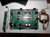
I know this is a DIY Audio forum, so asking for commercial devices might not get me very far, but hopefully someone here can help.

Increasingly, searching for electronics online has become a confusing slurry, further complicated by language and geographic divides.

Essentially, I'm looking for the cheapest, best-sounding stereo amplifier I can find, around 100W-per-channel (or higher). I would veer more towards "cheap" than "great sounding", but I'm not sure where those trade-offs are in Class D amplifiers.

I don't want to design it myself, but I could assemble from kit, if necessary.

My only hesitation with the kit approach is that, once again, I'm at the mercy of hundreds of different trade-offs and details that I don't have the time or money to experiment with.

At the moment, I'm operating under the understanding that a Class D amplifier will be the way to go - but that different Class D chips produce very different qualitative results with regards to audio fidelity. Those differences are further exacerbated by the wide range of designs in the world. Beyond that, it seems like power supplies are a whole other area of inconsistency and trade-off.
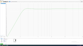
This seems like a place where people know this stuff, inside and out. Can anyone make some suggestions for me?

Thanks!

Octave DOWN pedal?

I have been looking at building or purchasing an Octave Down pedal which is simply a frequency divider. The biggest problem that I keep reading about is that they are ok for single notes but not chords and they have a lot of "fuzz" accompanied with them.
This has me wondering if anyone has tried to simply run a guitar signal through a variable high frequency bypass filter (say a 1MFD cap and pot) then run that through a preamp circuit to boost what is left of the signal back up and then to the guitar amp?


This would give a true frequency just without anything above say 400hz. It would not affect the chords like dividing frequencies does. Would it?


Is this feasible? Has anyone tried it?
Projects by fanatics, for fanatics
Get answers and advice for everyone wanting to learn the art of audio.
Join the Community
507,804
Members
7,889,065
Messages

Filter

Forum Statistics

Threads
406,271
Messages
7,889,065
Members
507,804
Latest member
m-tagg