Hi,
I have come up with this shematic for a dac board. Is it any good? Can you suggest improvements?
DAC board -
EasyEDA
I have come up with this shematic for a dac board. Is it any good? Can you suggest improvements?
DAC board -
EasyEDA
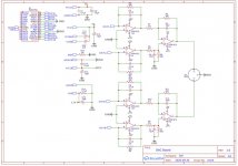
A copy of your schematic attached below. The value of R14 is shown as 0.1uf.
Also, you seem to have stereo outputs coming out on an XLR connector with a shared ground for both channels. That is not ideal, probably better to use two RCA connectors, which you would probably need to interface it to any other device downstream anyway. I have not checked your filter time constants or opamp loading, so no comment on those other than I would suggest you take a look at pages 19 and 20 of PCM1794 data sheet for suggested component values. All opamps should have local power rail bypassing at the power pins. For DACs it turns out that clock jitter, circuit layout, and power supply quality all affect the final sound. No information is shown for those things. It kind of looks like you copied some of the right side of the diagram shown on page 18 of PCM1794 data sheet. The left side of the diagram is omitted. What are you planning to use for a controller?
Also, you seem to have stereo outputs coming out on an XLR connector with a shared ground for both channels. That is not ideal, probably better to use two RCA connectors, which you would probably need to interface it to any other device downstream anyway. I have not checked your filter time constants or opamp loading, so no comment on those other than I would suggest you take a look at pages 19 and 20 of PCM1794 data sheet for suggested component values. All opamps should have local power rail bypassing at the power pins. For DACs it turns out that clock jitter, circuit layout, and power supply quality all affect the final sound. No information is shown for those things. It kind of looks like you copied some of the right side of the diagram shown on page 18 of PCM1794 data sheet. The left side of the diagram is omitted. What are you planning to use for a controller?
Attachments
A copy of your schematic attached below. The value of R14 is shown as 0.1uf.
Also, you seem to have stereo outputs coming out on an XLR connector with a shared ground for both channels. That is not ideal, probably better to use two RCA connectors, which you would probably need to interface it to any other device downstream anyway. I have not checked your filter time constants or opamp loading, so no comment on those other than I would suggest you take a look at pages 19 and 20 of PCM1794 data sheet for suggested component values. All opamps should have local power rail bypassing at the power pins. For DACs it turns out that clock jitter, circuit layout, and power supply quality all affect the final sound. No information is shown for those things. It kind of looks like you copied some of the right side of the diagram shown on page 18 of PCM1794 data sheet. The left side of the diagram is omitted. What are you planning to use for a controller?
Fundamentally this should be right. The IV conversion is done according to this Texas Instruments guide: https://www.ti.com/lit/an/sbaa333/s...ps%3A%2F%2Fwww.ti.com%2Fproduct%2FPCM1794A-Q1
And i think i don't have problem with the stereo output. (Figure 27) https://www.ti.com/lit/ds/symlink/p...ps%3A%2F%2Fwww.ti.com%2Fproduct%2FPCM1794A-Q1
I am planning to use an arduino nano for controlling the 2 boards. (Each board is responsible for one channel).
The output shown in figure 27 is for monaural mode. Is you schematic for 1/2 of a dac?
Also, your schematic shows a dac labeled PCM1794. Your link was to PCM1794A datasheet, which is correct?
Also, your schematic shows a dac labeled PCM1794. Your link was to PCM1794A datasheet, which is correct?
I will use this 2 from this kind of board. so, 2 mono = 1 stereo.
I will use the 1794A (corrected in the schematics).
I will use the 1794A (corrected in the schematics).
The opamp rail voltages might be below optimal. Don't know about for PCM1794A. For some other dacs it can be +-11v. Depends what works best in a particular case.
The opamp rail voltages might be below optimal. Don't know about for PCM1794A. For some other dacs it can be +-11v. Depends what works best in a particular case.
I am a novice 😀
i have followed this design: https://www.ti.com/lit/an/sbaa333/s...ps%3A%2F%2Fwww.ti.com%2Fproduct%2FPCM1794A-Q1
It should be good/optimal sice TI manufactures every part, so they must know their products.
The SBAA333 example you cite is just a fragment, but your phasing is different than the app PDF, yet the same on both outputs of the '1794.
Are you sure of how you're handling VCOML and VCOMR? Usually those provide the offset reference for the I/V converters.
Lumping all the grounds together is unlikely to give the desired performance.
You aren't showing how you plan to convince one channel of the '1794 to invert digitally. Right now you have both signal pins of the XLR driven identically, not 180 degrees out of phase -- the usual for a balanced output.
XLR's mate pin 1 before the other two. For that reason the standard is pin 1 - ground, not the more visually symmetrical pin 2.
Why build two when one could provide excellent performance? Not to hurt your feelings, but a dual-mono approach will not give the expected improvement in S/N+D without far more individual attention to the several grounds the '1794 provides.
Cheers
It requires setting the mono/2-channel pin and the channel select pin high or low as required.You aren't showing how you plan to convince one channel of the '1794 to invert digitally
Are you sure of how you're handling VCOML and VCOMR? Usually those provide the offset reference for the I/V converters.
You aren't showing how you plan to convince one channel of the '1794 to invert digitally. Right now you have both signal pins of the XLR driven identically, not 180 degrees out of phase -- the usual for a balanced output.
Why build two when one could provide excellent performance? Not to hurt your feelings, but a dual-mono approach will not give the expected improvement in S/N+D without far more individual attention to the several grounds the '1794 provides.
Cheers
I am handling the VCOML and VCOMR as the documentation say. If you have a better idea, please share (this is why I have posted in this forum).
I think, that when you configure the dac to work in mono mode, it automatically gives the proper phasing.
I build two, because why not. And if I can approach the 130 db range I will be happy. If you have any suggestion to improve the circuit, read the documentation of the dac chip and then feel free to cooperate. (Many of your questions indicates that you have not read it carefully enough)
- Home
- Source & Line
- Digital Line Level
- Sanity check