I am a newbie to building amps. I purchased the Nobsound EL34 DIY kit. This is the one with the tubes staggered. I have put it together ok, but the left channel has a bad hum (60Hz).I have swapped everything I can between sides and the hum is there without input. I have retouched some solder joints, twisted wires and shortened some wires to no avail.
My DC voltages look fine but not equal to ones on the schematic. Both sides are very close to each other. Next step I think is to view AC waveforms and record.
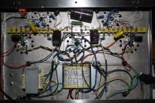
I have attached the diagrams I used to build it and am trying to get my photo of the chassis as built uploaded but have run into some kind of issue. Will continue to try. The pdf file is too big.
Any suggestions for getting rid of the left channel hum would be appreciated!
My DC voltages look fine but not equal to ones on the schematic. Both sides are very close to each other. Next step I think is to view AC waveforms and record.
I have attached the diagrams I used to build it and am trying to get my photo of the chassis as built uploaded but have run into some kind of issue. Will continue to try. The pdf file is too big.
Any suggestions for getting rid of the left channel hum would be appreciated!
Attachments
I don't see that on either of my drawings?
But no the black and yellow go to the heaters and nowhere else.
But no the black and yellow go to the heaters and nowhere else.
I don't see that on either of my drawings?
But no the black and yellow go to the heaters and nowhere else.
Yeah, someone more knowledgeable than me can probably give you a more definitive answer.
I have seen plenty of schematics that show a ground point for the heater wires, and plenty of other schematics that don't. I honestly do not know the science or wisdom behind one method or the other.
All I can say is that someone much smarter than me told me to ground all my heater wires, and I went from amps that hum to amps that a perfectly dead quiet.
There are lots of causes of hum, a bad solder connection, ground loop, wire dress (where signal wires run over other wires that have lots of 50/60 Hz such as the primary and secondaries of the power transformer), etc.
The schematic shows the input tubes have a 6.3V center tapped secondary, with the center tap grounded. That is correct.
The EL34 6.3V secondaries are not grounded. It is a good practice to connect a 100 Ohm resistor from one end of the 6.3V to ground, and a second 100 Ohm resistor from the other end of the 6.3V to ground (two EL34s, two secondaries, four 100 Ohm resistors).
Did you swap the input tubes with each other?
Did you swap the output tubes with each other?
Check the wiring of your RCA input connectors, volume pot, and input grid resistors and connections.
Notice that the two triode sections have 3 sets of parallel connections, grid, cathode, plate.
Check that the bypass capacitors of the input tubes are soldered well (and connected in the right polarity.
What are the DC voltages at the same points as listed in the schematic?
If you play music through both channels, is the gain the same (volume of the music the same)?
I can not see where the output transformers are, but the choke is on the bottom of the chassis.
By any chance, is the choke directly below the output transformer of the channel that has the hum?
How much hum do you have?
By any chance, is the choke directly below the output transformer of the channel that has the hum?
How much hum do you have?
On a similar amplifier I repaired time ago, relocating the filter choke solved the hum issue. There was magnetic coupling between the left channel output transformer and the choke underneath. Remove the left output tube and check if the hum is still there. Remove one mounting screw of the choke and rotate it to find the best orientation.
Referencing the heater to ground is a best practice.
Referencing the heater to ground is a best practice.
Did you use shielded cable from the volume pot to the grid of input tube (pin 1 & 4). The left channel is further away from the right. I would also check those input connections first. You can test this by removing that wire from the tube side and see (hear) what happen.
DC Voltages
Tube Pins Left Right
6n9p 2&5 165 164
6n9p 3&6 1.6 1.6
6n9p 1&4 0 0
EL34 3 340 341
EL34 1&8 17.7 17.2
EL34 5 0 0
EL34 4 283 283
tube side of choke 378
OT side 361
Yes the choke is directly beneath the left OT.
I will implement these suggestions and let you know.
Tube Pins Left Right
6n9p 2&5 165 164
6n9p 3&6 1.6 1.6
6n9p 1&4 0 0
EL34 3 340 341
EL34 1&8 17.7 17.2
EL34 5 0 0
EL34 4 283 283
tube side of choke 378
OT side 361
Yes the choke is directly beneath the left OT.
I will implement these suggestions and let you know.
Hello Everyone,
I have done the following:
Swapped tubes, no effect.
Moved choke, no effect.
Changed to shielded cable for left side volume control, no effect.
Swapped and changed inputs, no effect.
Cleaned some solder joints and cabling.
Checked wiring to schematic (traced) about six times.
Checked capacitor connections too.
Removed input on 6n9p pin 4 from volume control and there was
no hum. Not sure what this tells me? This line is shielded cable
now. No input nothing to amplify. Frankly pin 4 looks the same
on each channel.
Notes
The hum is unacceptable (loud) at low volume and decreases as volume
is increased.
There is 60Hz hum in the circuit on left and right side. Still have to
isolate and measure.
I will look for some 100 ohm resistors and implement.
I need to clean up some more heater lines near the tube sockets, there
is room for improvements on some of the tube heater runs.
Hum starts after amp warms on power on, once the sound is up the
hum is too. On power down, once the switch is turned off the hum
immediately stops while the sounds fades to no sound.
Here are the AC voltages I measured, all voltages are PP (peak to peak).
Tube Pins Left Right
6n9P 2&5 8.3 8.2
6n9p 3&6 700m 700m
6n9p 1&4 1 1
el34 3 400 400
el34 1&8 6.5 6.5
el34 8 8.5 8.5
el34 4 0 0
Choke tube side 12m
OT side of choke 0
Off to do resisters, wire shortening, twisting heater wire further. I am hoping to get some pictures from the scope, but its new and there is a learning curve!
Thanks to everyone who has added to this post, this is a great forum!!
Bob
Removed input on 6n9p pin 4 from volume control and there was
no hum. Not sure what this tells me?
Sounds like you are zeroing in on the problem. Try swapping lines out of the volume control to see if the hum moves to the other channel. You may have a sketchy control, ground, or loose input jack center conductor connection.
Bad hum at low volume setting which reduces as volume increases suggests that the 'ground' for the volume control has hum on it. Exactly how is the volume control wired? It is quite easy to accidentally introduce a hum loop at the volume control in a stereo chassis.
I would take out and check that tiny pcb which the volume pots is attached to. I had seen some that are done incorrectly. May be take this opportunity to up-grade that 🙂
Hi, have you also double and triple checked your wiring? It is very easy to make mistakes. We all have made wiring mistakes, putting the anode wire on the cathode pin, or similar. Or sometimes having a wire touching more than the pin that is supposed to be soldered to. Maybe a bit of solder dripped from a solder lug all the way to ground making a short.
rickaputo,
Your post # 12:
You mentioned pin # 4 on the input tube. It is supposed to be in parallel with pin # 1
Whatever you do to pin #4, you need to do the same to pin #1.
But do not just disconnect pins # 4 and # 1, connect them to ground (try through a 1k resistor to ground).
Your post # 12:
You mentioned pin # 4 on the input tube. It is supposed to be in parallel with pin # 1
Whatever you do to pin #4, you need to do the same to pin #1.
But do not just disconnect pins # 4 and # 1, connect them to ground (try through a 1k resistor to ground).
All,
As for the volume pot, I swapped the output lines and there was no effect, hum still on the left. It looks ok, but I will inspect it further. Possibly lift the ground this time.
I am constantly reviewing the wiring, solder joints and component values and orientation.
I have 100 ohm resisters on order for the heaters and will try 1k from pin 4 to ground.
I was poking around with the scope, and found that the EL34 heaters vary greatly from left and right. The left side has about 10Vpp on pins 2 & 7. The right side has 400Vpp. Interesting???
Bob
All,
I have added all the resistors on left side but still hum.
I swapped heater wires from left to right and the crazy voltage followed. After the resistors were added the heaters with crazy voltages are gone.
The 1k resistor to pin 4 on 6n9p did not affect anything.
Well it looks like I will go back and start from the beginning to start there again. Tracing circuits, etc.
Can someone point me to an acceptable volume control for this amp? I will replace the crappy one they sent.
I believe I tried all the suggestions above. So starting over.
Bob
- Home
- Amplifiers
- Tubes / Valves
- Nobsound EL34 DIY with left channel hum