Speaker Protection Relay Grounding

Hello All,

I am building my first amp and using a star grounding system. The speaker protection relays are suggested to go to that grounding point. My relays will be mounted to the rear panel next to the outputs.

Can I simply use the same mount lug that I secure the short "earth" wire from the IEC socket to the chassis? Since that same lug is tied directly to the same star ground point itself, would doing this create a loop of some sort that I am not visualizing?

Cheers,

David

HIP4080 based amp issues with DC offset (is it ?)

Hello everyone !

Long story in short - it's a cheap class D hip4080 amp using B31N20D for output mosfets. Rail voltage is almost 70v at 14.4v b+ input

Works fine with no load connected. Sinewave is good, no distortion.
Once load is being hooked up it goes into frenzy mode 😀 . I've tried with different dummy loads values and a subwoofer.

What have noticed is that if you turn on the amp and let it idle with no load connected for 10-15 seconds and connect a load afterwards it works just fine.

I've measured DC offset between the - and + speakers output. And here it is. Once the amp is being turned on there is the FULL rail voltage difference between the + and -, that 70v volts difference. Then It slowly sinks down to a ~ 0.7v after 15 seconds.

So if you connect a load after the first 15 seconds when the amp is being turned on and the DC offset has been stabilized - it works just fine.

If you turn on the amp with a load connected on - it draws a lot of current and there is ....well you know what happens when You have +70volts difference between + and - speaker terminals (i'm glad i'm using dummy load this time, not a subwoofer in the tests).

My question is - is it the HIP4080 or a leaky Mosfets. I don't see a muting transistor at the board (don't have schematics due to this being really cheap chinnese amp).

Both HIP4080 and the mosfets IRFB31N20D are not easy and cheap to find over here, so is there any test i can do to determine where the exact fault is ?

The amp has been carefully re-caped, resoldered and cleaned up.

Attachments

  • upload.jpg
    upload.jpg
    363.9 KB · Views: 252

Datasheet for CDM9 / CDM9 Pro

Hi.

I've a micromega microdrive, and i want to make a DIY konverter for this drive.

The mechanism should be a CDM9 or CDM9 pro, but i'm not able to find any datasheets on this. Can anyobe help me ??

I'm planning to use the I2S (if it is present) and place the clock in the converter in order to minimize the jitter.

The converter will probably a TDA1543 without oversampling.

Blaupunkt Cassette

Hi I've been working on a Bremen SQR46 with distorted audio on bass and mid range , so far I've replaced all the electrolytic caps on the board and cleaned up the pots. Top end is sweet now bass and mids signal is degraded.

I swapped out one of the output ic's but still no change.

Also when switching balance from left to right you can still hear low volume audio when there should be none?

Distortion is present on radio and cassette.

Any help with this appreciated, thanks

Vandersteen 2C persistent hum in one channel

Hello

I'm an intermittent lurker and 1st time poster looking for advice. I purchased the pair of 2C from a dealer back in the 80s and I've always loved them and they have been trouble free. I've been away from audio stuff for some time -home projects, career and vintage Alfas. Recently I started hooking up my old equipment again.


My Hafler DH101 pre amp has died so I hooked up my old Kenwood AV receiver KRV 9030 and was glad to be running the Vandys again. After a year of intermittent listening a slight hum emerged on one speaker and it was not noticeable when listening at volume. Several months after that one day the hum became noticeably louder. You still really can't hear it at volume but in between tracts or when you are loading the CD player it's there and its worrisome.

I've swapped cables and the issue persists no matter the channel so the fault seems to be with the speaker and I'm guessing the crossover network. My experience is limited in electronics but I'm recalling if I'd had no sound to look at the caps first when evaluating. With a hum, what is the most likely suspect? I'm no engineer but I've heard some sample hums on forum sites and it sounds to my untrained ear like a 60hZ thing and not an open loop.

The Vandy's design makes crossover access difficult and I don't want to start wildly taking stuff apart. My gut, however tells me the cross over needs to be evaluated regardless. A visual may ID burnt components and then its on to bench testing. I'm open to suggestions and your experience. If its bad resistor or another component, I'm thinking both crossovers need to be brought back at the same time-resistors, caps etc

Thoughts and suggestions appreciated

thanks

steve

Any audio programmers?

Looking at the forums categories, I get the impression much of diyAudio is aimed at electronics and hardware but I'm wondering if there are any audio programmers here? I'm new at it (new at both audio and hardware, really) and am currently learning JUCE with C++ to make a couple quick starter VST's (gain knob and simple EQ). Interested in what other people are using... I'm only using JUCE because it's the first result I got when I looked up VST programming. 😀

Oscilloscope Multimeter

https://www.amazon.com/gp/product/B...XHV26&linkId=bbcede180b9ebdc6f4f091e24640bb31

I saw a guy using one of these multimeters to check the compression and fuel pump on a car. He used it with the "Fuse Buddy" https://www.amazon.com/307M-Fuse-Bu...6K6GFEJAMCT&psc=1&refRID=2629YWMRV6K6GFEJAMCT and current probe https://www.amazon.com/gp/product/B...GDVWM&linkId=dc922fa3bb981e4a4e1b19463fee3bc8 and it was genius.

I could use one of these in my electronic adventures too. I need an oscilloscope (better than this but it will do). I'm thinking about pulling the trigger. I work on cars and this will save me time and effort.

Here's the video. The guy is a character but he's smart and clever.

Here's How a Real Mechanic Checks a Used Car Before Buying - YouTube

So I was wondering if anyone has experience with a product like this, and if there are maybe better affordable alternatives. To me, a compact and inexpensive oscilloscope would be very handy.

Thanks.

Thoughts re: Unusual 845 amp

Hi all,

I picked this up today for the same price that was marked on one of the spare tube boxes. Those OPTs are hefty. I pulled the cover off and discovered a transformer underneath that is indeed that big, but potted in wax. As you can see, the PS is quite a mash mash of vintage stuff. Haven't seen many pairs of 3B28s. The HV supply is on a mechanical timer.

Based on a quick look (you folks know better than I) I see a half 6sn7 to the grid of half a 5687 to the grid of a 6sn7 strapped in parallel to the grid of the 845. A quick google suggests you don't see that topology every day either.

There are a bunch of receipts in the bag for repairs spanning 2005-2013. (The owner at that time, I think the second, paid $240 for a shop to build an umbilical terminated with electrical tape!). It evidently worked when sold to the third owner; a solder joint broke during transit; some idiot popped an 8sn7 into one of the holes; it didn't work; and then on the way to the shop he stopped fast and broke the power tubes. So he sold it to me. But the point is that it appears to have run for quite awhile and been modified and updated from time to time.

I know this topology isn't ideal. I also know the soldering is scary bad. (Folks say my builds aren't pretty or terribly safe, but at least I'm better than this!) I don't have time right now to re-engineer the entire thing. But, I could certainly clean up the bad joints; replace the scariest bits; toss in some cheap 845s; and if it powers up nicely (I've got a variac and isolation transformer and know how to do that), see if it works. (I also don't love the safety earth through the umbilical, thoughts?)

Is that a terrible idea? I know it needs a better topology to make more power. And that I'd be better off with a simpler 300B amp. But boy would it be a cool looking and heat-wasting way to make music!

Paul

Attachments

  • Big Red.jpg
    Big Red.jpg
    828.1 KB · Views: 592
  • Signal Upskirt.jpg
    Signal Upskirt.jpg
    1 MB · Views: 582

Atypical Web-Crossover Calcuator - Slope vs. Order

Looking to do some simple guestimates for Butterworth crossovers I found this one that unlike other web-page based calculators has an extra option for slope independent of order.

Also, the values differ for low and high pass unlike the others that use the same component values and just exchange position in the circuit for LP/HP.

It makes sense to me that adjusting values will change the slope but how does that fit with the definition of a Butterworth filter and also (more importantly) what is the price to be paid for getting a steeper slope from a lower order filter?

Thanks

SB Acoustics SB17MFC35-8 (Elsinore Speaker Set)

Up for sale is a brand new set of 8 x SB Acoustics SB17MFC35-8. I bought these to build Joe Rasmussen's Elsinore speakers (see huge thread on diyaudio). Ended up finding a set of 8 x SB17NRXC35-8 speakers locally after I had already bought the MFCs, hence the reason they're for sale.

The Elsinores sound fantastic. I'm half tempted to keep these speakers to build the upcoming Hamlets, but thought I'd check interest.

I'd like to clear $40USD each on these. Only selling as a set of 8 at this stage, but let me know if you are looking at a set of 4.

Prefer to ship within Canada, but happy to send to the US if you research shipping.

Happy to take as many pictures as you like. Also no issues connecting a multimeter and measuring each speaker to show that they work. Just ask. 🙂

Also have some crossover parts that we can work out a deal on...
- C1: 2x Jantzen Superior 1.8uF caps
- R1: 2x Mills Resistor 2R Ohm 5W MRA-5 Series
- C2: 2x PartsExpress 33uF caps (can throw in for free)
- L2: 2x Jantzen Audio 1.0mH 15 AWG Air Core Inductor Crossover Coil

- Might have some others lying around as well.

A/D converter input buffers

Hello!

As an experiment, I am building a simple A to D converter for stereo audio using a cirrus logic chip. I have looked at some designs and noticed all of them use opamp buffers before the differential input to the A/D converting chip.

Could someone explain or shed light on the fact to if its possible to just use a matching transformer instead of the usual opamp buffers? If not, why so or could it be made to work?

I can see that in the usual buffer circuits, they implement low pass filters. I cant really figure out why this would be needed?

Any help would be much appreciated!

Thanks, Lewis

Turntable Cleaning

I've got a late 70's model Toshiba SR-FX70 Quartz lock automatic turntable that goes with a stereo set I have.

I believe the turntable was dropped at some point and the masonite bottom, and inner rails that hold it in place were busted in on one corner and I'm finally getting around to fixing it. It seems to work just fine other than not sitting level due to the busted in corner.

I figured while I had the bottom off I would try and give it a decent cleaning.

I've never messed with the internals on an automatic turntable before and before I go blasting away with the Deoxit I thought I might seek a little advice.

Is there anything I should try and avoid with the cleaner and lube?

Any particular areas I should try and focus on?

Any additional things to check out while I'm in there?

My plan was to spritz all the mechanical workings with Deoxit and give it a follow up with Faderlube.

Thanks,
ndpPXL_20210310_213858015.jpgPXL_20210310_214730737.jpgPXL_20210310_221455428.jpgPXL_20210310_224746708.jpgPXL_20210310_224759367.jpg

Popping noise through phono stage

Hi All,
I would appreciate a little help with a problem that has become a bit of a head scratcher.
I have recently fired up my turntable front end after having built the Transcendent Sound phono stage and whilst initially everything was fine with a Cartridge Man Music maker, it all started to go down hill when I switched over to my Wilson Benesch Carbon low output MC.
I had a pair of Sowter SUT's which have been installed in the Transcendent phono stage, giving me both MM and MC options. Whilst the Benesch cartridge plays music superbly through the SUT's, there is a lot of hum which I cannot eliminate. I therefore started investigating the build of a battery powered head amp
Having built the Hart Electronics 1450 Linsley Hood phono stage some years ago, I was digging through the web and came across Paul Kemble's excellent site where he has a schematic for a low voltage head amp designed by Linsley Hood, which is basically exactly the same circuit topology as on the input stage of his phono amp, just with different resistor values to accommodate the lower supply voltage. Bingo. So I built it, and it works superbly well, except for one big problem.
With it in circuit I constantly get popping and spitting noises through the speakers, and this is WITHOUT the turntable playing or rotating, so it is nothing to do with record surface noise.
With the Benesch cartridge plugged into the SUT's there is no spitting, just hum.
So am at a bit of a loss to know what may be causing it and how to solve it. Hopefully some-one on the forum will be able to point me in the right direction. Schematic is below. Have made a few mods. As I couldn't get matched NPN and PNP transistors, have substituted BC549B's and BC559B's which whilst not perfectly matched are a lot closer than the original BC214's and 414's that I had managed to get hold of. Even so, was not able to zero the output, so have got rid of the 68k resistor and the 47k trimmer, and have put a blocking capacitor on the output.
Ironically, in desperation, I dug out the old Linsley Hood phono stage and plugged that in circuit. It did exactly the same thing with the spitting and popping.
So in summary. No record playing or spinning, just everything at idle.
Music Maker into Transcendent MM phono stage - No popping and quiet
Benesch into SUT's in Transcendent phono stage - No popping but hum
Benesch into JLH Head amp and then into Transcendent MM stage - Popping, but no hum
Benesch into old JLH 1450 phono stage - Popping and some hum (I assume as mains powered)
I look forward to your responses.
Thanks.

Attachments

  • JLH head amp.jpg
    JLH head amp.jpg
    144.9 KB · Views: 207

FS: Yaqin MS-20L integrated EL34 amp $500

SOLD

Yaqin MS-20L integrated amplifier, purchased new in 2011. Located in central Alabama.
4 - EL34 output tubes.
8 - 6J1/6AK5/M8100 input/phase splitter tubes.
4 RCA type inputs which are selectable on the front or with the remote.
4ohm and 8ohm taps for speaker connections.
50 watts per channel in Ultralinear mode and 25 watts per channel in Triode mode.

The output tube bias is easily adjustable without disassembling the amp.
Bias adjustment tool included.
Remote control included.

I have 2 years in electronics school and passed the associate Certified Electronics Technician exams and state licensing exams in the 70s. I made the following upgrades to this amplifier.
1)The motorized factory volume control was replaced with a Blue ALPS potentiometer, which is not motorized.
2)A Blue ALPS potentiometer was also placed into the negative feedback circuit (NFB) to allow adjustment of the gain and tone.
3)Coupling capacitors replaced with Obbligato Gold capacitors.

The following tubes are included:
4 - Svetlana Winged C EL34WC date codes 2005 and 2007, these are genuine Winged C not the new reissues.
4 - Mullard M8100 phase splitter tubes.
4 - Voskod 6J1P-EV input tubes.
(This is $200+ worth of tubes)
The owners manual and schematics are included.
I took photos with and without the "cage" on it. I can take more photos on request.

The other items in the photos ARE NOT INCLUDED.

Thanks for looking!

I am going a different route for my audio system and am selling this amplifier. I will be happy to demo it for serious buyers. I would prefer not to ship this as it weighs 45 pounds but would be willing to at the buyer's expense.
https://www.diyaudio.com/forums/att...integrated-el34-amp-500-a-20210314_102341-jpg
https://www.diyaudio.com/forums/att...integrated-el34-amp-500-a-20210314_102345-jpg
https://www.diyaudio.com/forums/att...integrated-el34-amp-500-a-20210314_102351-jpg
https://www.diyaudio.com/forums/att...integrated-el34-amp-500-a-20210314_102404-jpg
https://www.diyaudio.com/forums/att...integrated-el34-amp-500-a-20210314_100450-jpg
https://www.diyaudio.com/forums/att...integrated-el34-amp-500-a-20210314_100456-jpg
https://www.diyaudio.com/forums/att...integrated-el34-amp-500-a-20210314_100504-jpg
https://www.diyaudio.com/forums/att...integrated-el34-amp-500-a-20210314_171800-jpg
https://www.diyaudio.com/forums/att...integrated-el34-amp-500-a-20210314_171808-jpg

Attachments

  • 20210314_102341.jpg
    20210314_102341.jpg
    171.7 KB · Views: 157
  • 20210314_102345.jpg
    20210314_102345.jpg
    163.7 KB · Views: 140
  • 20210314_102351.jpg
    20210314_102351.jpg
    180.4 KB · Views: 132
  • 20210314_102404.jpg
    20210314_102404.jpg
    177.5 KB · Views: 134
  • 20210314_100450.jpg
    20210314_100450.jpg
    128.6 KB · Views: 132
  • 20210314_100456.jpg
    20210314_100456.jpg
    215.4 KB · Views: 96
  • 20210314_100504.jpg
    20210314_100504.jpg
    178.3 KB · Views: 95
  • 20210314_171800.jpg
    20210314_171800.jpg
    271.3 KB · Views: 87
  • 20210314_171808.jpg
    20210314_171808.jpg
    290.7 KB · Views: 90

Lampemètre Ultra-Compact - operating points for testing

I have a pile of 12a*7 tubes, mainly purchased 20yrs ago when I first dabbled with tube preamps. Many are NOS, but I also have quite a few that are definitely not brand new (usage TBC). I wanted some method of measuring the performance of each, primarily for my own interest, but also to help me gift/sell the tubes if I decide to do this in the future.

I purchased the Lampemètre Ultra-Compact kit from Alain at RadioElec. Alain was extremely helpful and answered a number of questions before I ordered the unit.

Lampemetre Ultra-Compact - Digital Vacuum Tube Tester MO0002 : RADIOELEC : Electronics Components and Modules, specially for Audiophiles and Radio-Ham

My plan is to test each section of each tube at defined operating points, then use Excel to calculate GM/Rp/μ.

Initially I chose the following operating points:

Va 145V, Vg 0.0V
Va 150V, Vg -2.0V
Va 150V, Vg -4.0V
Va 250V, Vg -8.5V
Va 250V, Vg -10.5V

I've realised that I'll need to add at least one more operating point with higher Va and same Vg, so I can calculate Rp & μ.

Before I start working through the tubes one by one, please can you let me know if I'm on the right track, or if I'd be better to change the operating points? I'm not really sure of what I'm doing here so any guidance would be massively appreciated!

Attachments

  • IMG_2372.JPEG
    IMG_2372.JPEG
    799.5 KB · Views: 165
  • IMG_2373.JPEG
    IMG_2373.JPEG
    951.8 KB · Views: 159

line array theory in real life?

Evening!

I'm trying to do deal with a very reverberant cathedral with 35 meter long ceilings, had the idea of constructing 10-meter high straight-line array from the floor, using full range 2-inch BMA tectonic drivers(tectonic tebm35c10), these drivers have almost perfect horizontal dispersion till 20 kHz, which is desirable here to cover a wide range of the audience,
the goal here is to increase speech intelligibility, music is not of interest and the only important frequency range is from 100 Hz till around 6 kHz, the cabinet is going to be around 5.5 cms wide, and around 5.5 cms center to center, comb filtering shouldn't happen in the frequency range of interest, will probably use an HPF and LPF on everything else to protect the drivers,
In theory and using this formula :d = 1.5 f h2, I'll get a nearfield response from 100 Hz upwards up to 15 meters, which is required in the cathedral to cover the people,
as long as they're in the nearfield of the line arrays, speech intelligibility and clarity should be high, and I'll be losing 3 dB for each doubling of the distance
10 meters of line arrays would equate to around 200 drivers or 100 dB/watt at 1 meter, so I should lose around 10 dB only at the end of the cathedral if using the line arrays next to the alter.

2 of the 10-meter arrays with a very wide horizontal dispersion and limited vertical dispersion provided in the nearfield of the line arrays should be enough to cover it all

is there something wrong theoretically? something that wouldn't work out well in a real-life scenario?

Need Help - PC to Stereo

Hey All,

I have a decent 2 channel stereo that has no sand in it... All tubes.
I want to be able to play music from my computer (stored files or streaming) through the 2 channel system.

The distance is a bit far for an RCA mini to dual RCA cable run plus it would have to run across the ground past the entry door.

I do have network access at both the PC and the 2 channel rig.

What are people using to stream or send music from their PCs to their amps these days.

Pardon my ignorance, I'm an old school analog guy.

Thoughts?

Jumpering around output buffers on the Pete Millet NuTube buffer circuit

Hi Gang,

VERY FIRST thread here on DIYAudio, and fairly newb-ish to circuit-building...so BE NICE TO ME! I'm actually pretty good at sourcing parts and building guitar stomp boxes etc from scratch using just the BOM and the PCB diagram, but I'm not educated yet and reading electrical schematics, or I'd be able to answer the following question myself:

I recently finished building Pete Millet's NuTube Buffer circuit, link here...
Nutube 6P1 Buffer PCB
...and am interesting in trying a couple of the mods he recommends. In particular, I'd like to try jumpering around the Mosfet output buffers in his circuit, as he states here...

"Since the 6P1 has relatively high plate resistance, I also put MOSFET followers at the outputs. If you are driving something that has high input impedance (> 100k or so), you can not populate the output buffers and jumper around them if you want."​
So I guess I'm essentially looking for an idiot-proof answer along the lines of "start your jumper off of the R-whatever output hole and then finish it at C-whatever input hole" or thereabouts, so I literally know where to physically solder the jumper wire on the PCB...if that isn't too insanely f$%ing dumb for this forum.

I've tried communicating with Pete about stuff like this via email but I've had 50/50 luck on that and I'm sure he's a busy guy, so you folks are my next stop ;-)

Change notification on multiple threads ?

When I started getting used to this forum, I subscribed to many threads, and being smart and all, had instant emails set.. Now, my inbox is bombed lol.. Now that Im really smart, I set the notification to no email and visit the subscribed threads as my home page..
How do I change from email to none on any of them, and can I do it for all ?


EDIT ... Looked a few times.. couldn't find how..

I post the question above and Instantly see it...
Strange how the universe works... lol


Disregard - Delete if you want...

My Prototype Whammy style PSU

This is a fully built prototype power supply which is very similar to the one on the Whammy HPA utilising the very effective CRCRC filtering just without the configuration options. It's set up for +/- 15v and would suit a headphone amp build. Size dimensions are approx 220mm x 75mm. Note the transformer is different to what's pictured as it was swapped out for a Talema 22v instead as I needed the 18v one for another project.

Looking for £50

Shipping worldwide at your own expense.

Attachments

  • IMG_20200512_184248-930x620.jpg
    IMG_20200512_184248-930x620.jpg
    84.2 KB · Views: 187
  • IMG_20200512_232454__01-1024x768.jpg
    IMG_20200512_232454__01-1024x768.jpg
    132.5 KB · Views: 183
  • IMG_20200512_232437__01-1024x768.jpg
    IMG_20200512_232437__01-1024x768.jpg
    130.6 KB · Views: 189

  • Locked
The Sliding Scale of Audio Rules

Hopefully, a sensible discussion can come from this thread.
It seems that others I've posted have become controversial dead-ends.

So where do you think you gravitate to on the scale shown, and along with that, where do you believe people in general seem to wander to?
And why?
And keep in mind,the grey area is quite wide.


Have at it!

Attachments

  • b-w scale.JPG
    b-w scale.JPG
    7.9 KB · Views: 350

Schade P2P and gNFB in RH807

With the help of @Baudouin0 I have added gNFB to the RH807 amp as shown below. I left the original 100K Schade plate to plate feedback in while adding the 2.2K gnfb resistor. My question is there any rule of thumb on the balance between Schade and gNFB that should be used? Or is done by ear and measurements alone?

Attachments

  • rh807wgnfb.png
    rh807wgnfb.png
    44.6 KB · Views: 554

EL84 PP - Enough Power?

Having completed my first DIY speaker build in years (Seas A26), I'm really wanting to try a lower power tubed amp again. The A26 is a true 88dB efficient, 8 ohms minimum speaker, with an ultra-simple x'over too, no less.

I listen mostly at moderate levels, with the occasional loud burst, but my open floor plan room's on the large size (speakers 7' apart, me 9' back, another 10' behind me, to my left is the dining area).

In your experience, am I good with 10-15 clean watts here, or stick with EL34, etc. ?

LM3886/LM3876 Hum and motorboat sound come Ground line

Lm3886.png

Lm3886-error.png


problem LM3886 input and ground interconnect with audio source

no source connect no any hum or motorboat sound but preamp or source connect hum and moterboat sound start

lm3886 input to ground add 100 ohm resistor same hum and motorboat sound come, connect preamp or any audio source LM3886 input to LM3886 Power ground interconnect and start hum and moterboat sound come

this error LM3886 power supply or LM3886/LM3876 IC or some thing, see lot of thread hum and motorboat problem but not real solution, this is not ground loop error

please help

Creating a new headphone listening room. My insanity inside

The wife hasn't left me yet, but she did walk in and just say "wow" and walked away. It wasn't a good "wow". 😀 I don't think she realized just how many existed in our home until I hung them up.

We moved and now I'm finally able to create a dedicated headphone listening room. Still have a ways to go with the pegs, have more headphones to hang, but this is what I've got so far! Collected all these over the years, and more.

I'm a collector of the bizarre. Most are not too pricy, but all are dear to me. My favorites are my AKG k444 that I converted to bluetooth, (I like it for the aesthetics, it's just a piece of it's time). The 6xx is my favorite all-rounder, but the AKG k240DF is catching up. For moderns, the Sivga SV-004 is mighty awesome, and the KPH-30s are my portable choice. The Pioneer A-1000's are okay sometimes.


(The Sonic Pro-26's next to the Pioneer SE-L40's are SURPRISINGLY great sounding. Dare I say, they sound better than what they're trying to copy.)


Many of the ones without cables are either converted to balanced or bluetooth. Even have some bluetooth ones converted to wired! Balanced ones are usually higher impedance cans, only to achieve a more suitable volume level when used on the go with my Fiio and A/K devices. Bluetooth conversions were for a retro modern style and portability without the blasted cable making me trip while listening at work.

Attachments

  • IMG_20210312_190913041.png
    IMG_20210312_190913041.png
    946.1 KB · Views: 138
  • IMG_20210312_190920104.png
    IMG_20210312_190920104.png
    945 KB · Views: 133
  • IMG_20210312_191247218.png
    IMG_20210312_191247218.png
    945.8 KB · Views: 127
  • IMG_20210312_191413395.png
    IMG_20210312_191413395.png
    946.8 KB · Views: 134

F/S Horn Madness

Used Design Direct Sound HD fiberglass horn flares. DMB 12n Pro & DVB 15n Pro. Visit DDS Horns, Design Direct Sound, DDS, fiberglass horns, horn lenses, fiberglass lenses, line array, waveguide, waveguides, asymetric, community, tweeter horns, mid-range, speaker lenses, speaker horns for specs. Excellent high-efficiency project parts.
Very cheap to buy. Shipping...? NYC metro area delivery/pickup possible.

Lets talk!!

Jim

Attachments

  • 20210306_105701.jpg
    20210306_105701.jpg
    526.8 KB · Views: 547
  • 20210306_105706.jpg
    20210306_105706.jpg
    647.1 KB · Views: 545
  • 20210306_145740.jpg
    20210306_145740.jpg
    673.5 KB · Views: 541
  • 20210306_122752.jpg
    20210306_122752.jpg
    713.9 KB · Views: 524
  • 20210119_114447.jpg
    20210119_114447.jpg
    705.2 KB · Views: 505
  • 20210306_145734.jpg
    20210306_145734.jpg
    851.4 KB · Views: 311
  • 20210306_105824.jpg
    20210306_105824.jpg
    793 KB · Views: 178

Rotel RB-870BX renovation, C609 question?

I am fixing one of these which includes changing most of the caps, the C609 highlighted in the picture is a 1uF 50v elyt which I was intending to change for a Nichicon gold tune but it turns out I don't have the correct value.

I have a 1uF MKT film cap and larger values 47uF/50v gold tunes but as I am not into details of amp circuits I don't know what C609 is doing or what to consider from a cap point of view?


nxMyydz.jpg

Cyrus Pre 7.5 repurpose as passive?

I have a failed Cyrus Pre 7.5.

A few years ago one channel started to emit an unpleasant hum shortly after being switched on. It sounded like a wave and occured even with the volume turned all the way down. I tried simple things like swapping cables, speakers etc but to no avail and concluded that the pre was just faulty. Headphone output worked fine. Repair from Cyrus was uneconomical and I could find very little information about undertaking a bit of simple DIY. A couple of capaciors measured below tolerance so I replaced these just because I could, it made no difference.

I stored it and on switching on recently, it powers up but then goes into standby and fails to come out of that. My skill level with electronics is low, I can solder safely and successfully, can use a multi-meter and understand that pratting around with anything live is potentially deadly. I do however wonder about using the casework and perhaps some of the controls to build a passive pre-amp and wondered if this a viable project? Indeed if anyone has tried this with this particular preamp and could direct me to further reading.

As an aside I have just seen something odd, a surface mounted capacitor placed on the board with what appears to be reversed polarity. As I have owned this from new that is how it left the factory and it worked fine for years. I thought that a reversed cap would have exploded? Please see photo attached.

Attachments

  • Cyrus Pre 7.5.jpg
    Cyrus Pre 7.5.jpg
    106.6 KB · Views: 117

Beard 101 power amp - capacitor selection

Hi,

I've always been a keen DIYer but have always been more of a fitter rather than selecting components.

On my Beard 101 power amplifier one of the 4 main capacitors on the HT circuit has failed. They are LCR 400uF 350VDC, which are no longer made and I cannot find any NOS after much hunting. So it's time to select alternative components.

My question is: besides matching the voltage and uF ratings is there anything else I should be considering?

I believe I am right in that the voltage rating can be higher but not lower and there are physical dimensions to consider. I am completely lost when it comes to reading the specification sheets of alternative capacitors, plus I have no actual specification on the LCR originals.

Any advice would be gratefully received!

Ruark Dialogue and Prologue DIY crossovers help for a newbie

Hello, first post and only started looking at building crossovers the last couple of days so please excuse any rookie mistakes.

I have a Ruark Dialogue One centre and Ruark Prologue Fronts with Ruark Icons rears.

I am really concentrating on the Dialogue centre at the moment to start with and if I don't mess it up completely will do the fronts.

Searching for info is difficult with the age of the speakers 1997 but a few bits I have found.

DESCRIPTION

Frequency Response: 62Hz - 22KHz +/- 3dB (free space conditions)
Nominal Impedance: 6 ohms
Amplifier Requirements: 25 - 120 watts
Sensitivity: 89dB/watt @ 1m
Dimensions HxWxD: 17.5cm x 48cm x 21cm
Weight each unpacked: 9Kg
Color finishes: Natural Cherry, Red Cherry, Natural Oak or Black Oak Veneers

Dialogue One
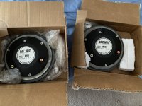
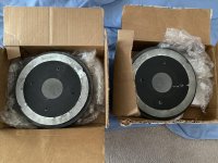
Design Type: Two way with one 28mm fabric dome tweeter, two 5" felted bass drivers, in an infinite baffle type enclosure.
Cabinet: 15mm MDF throughout.
Colour Finish: Oak Finish.
Crossover: Damped second order at 2.8Hz, five element with air cored inductors, both polypropylene and low loss electrolyic capacitors and high power resistors.
Frequency response: 70Hz -20KHz+/-3dB
Nominal impedance: 6 ohms.
Sensitivity: 90dB 2.83v.
Power handling: 150 Watts long term.
Dimensions H x W x D: 17cm x 48cm x 20cm
Weight each: 8Kg

There are also 2 versions which seems to mix up the searches, but I believe I have the original Dialogue One looking at pictures the tweeter was different in the 2nd revision.

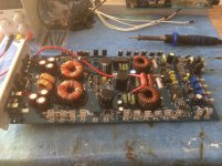
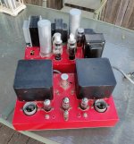
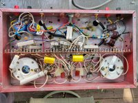
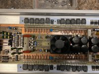
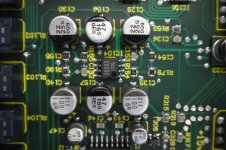
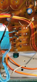
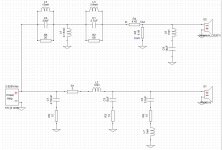
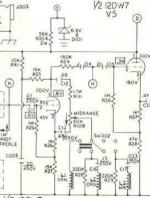
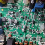
So it is a 2nd order 2 way crossover at 2.8khz and it looks like it is similar to the Ruark Epilogue which I have had in bits and taken a picture of the crossover.

Originally I was thinking about replacing like for like with better components but then I thought if I am going to put the effort in to do that I might as well do more.

So using XSim I have put together a 1st order 3 way design because I think the fronts would really benefit from this, so I might as well do the centre the same way.

The original crossovers have a 10w 7.2ohm resistor so I believe this means it is around +6db over the drivers so worked around that with the new crossover.

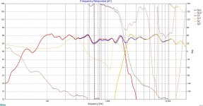
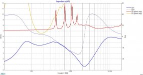
So my plan is to take some measurements using the gated time window method or as close as I can get to it of the drivers and tweeter separately without the crossover in place and with the speakers in the cabinet so should then know exactly what -/+ I need to deal with and where the distortion starts/finishes for each as well as cabinet effect.

Then tweak the crossover design, I am thinking currently crossing over around 500hz and 4khz.

Does this sound sensible and am I missing anything blinding obvious.

Planning to use Clarity Caps, Mundorf Inductors and Resistors, cost should be around £90 per speaker.

Any opinions / help would be much appreciated.

Cheers

3way-crossover.jpg

3way-crossover-freq.jpg

3way-crossover-imp.jpg

Product Information & HELP ?

On My ' Harman Kardon AVR 20 Dolby Pro Logic Suround 5.1 AV

Receiver '.

There Is Not Any Sound Playing Out Of The Suround Sound's Right &

Left Rear Speaker's. But When I Press The 'TEST' Button The Tone Is

Heard Just Fine Through The Left & Right Front Speaker's & Also The

Center Chanel Speaker, But The Rear Suround Sound Speaker'sPlay's

The Test Tone At A Very Low Volume.

The User's Manual Say's On The Original Remote Control ( Which I

Don't Have ) You Can Adjust The Rear Speaker's Volume With The

Remote Control. Is This The Only Way The Rear Suround Sound

Speaker's Can Be Adjusted.

First Watt CSX2 simulation

First Watt CSX2 simulation and build

I have completed F2J, it was fun, great funny amp that heats lower when you play louder, thanks to Mr. Kirchhoff.

While waiting for TFH-51S VFETs from Japan and plans from Mr. Pass it's time to build something different. As I have a few pairs of 2sk82/2sj28 and I like a minimalist approach I created a simulation of CSX2. I used fully symmetrical spice models from Mike at Audiomaker - the capacitancies are not specified. The THD at 1W 8 Ohm is 0.098159% (3rd harmonics at -60dB FS). The gain is only about 2.81x. I biased them at 1.5A as per Papa's recipe.

I have used JT-123-FLPCH instead of JT-112-L as I have a pair purchased a few years ago for F6 - not sure if there is any disadvantage of using them in CSX2.

Has anyone built this amp? I would like to design PCBs. I am wondering if you could share some hints, ideas, for example what size of heatsinks have you used, any photos? Would be grateful for sharing your experience 🙂


it-wasnt-me.jpg

Attachments

  • csx2-fft-at-1W-8Ohm.png
    csx2-fft-at-1W-8Ohm.png
    6.9 KB · Views: 438
  • schematics.png
    schematics.png
    21.8 KB · Views: 438

Advice for Power Supply - Pete Millett Balanced NuTube

I am looking for some advice, please. I need to build an appropriate power supply for Pete Millett's Balanced NuTube design.

It is likely that I will build both a line stage and headphone version. So, I'd like the power supply to support the current necessary for low impedance headphone loads. Per Pete's article, I'd prefer to run it off +/- 15V with a min current of roughly 0A200 or more per side for good measure. I'm a bit new to this. I think if I don't build it "dual mono" and use two PSUs, then I'd need a PSU that can work up to 0A400. I, like most people, seem to err on the side of more is better.

I have been experimenting with trying to model a PSU, but I am out of my depth at the moment. So, I would prefer a PSU with ready-made PCBs, a known-tested BoM, and some level of support from a forum thread and/or the designer. I don't have a lot of concerns, but many power supplies have an enormous number of rectification, snubber, and filtering choices. Board mounted transformers (similar to the WHAMMY kit) would be a plus, but I can work with a donut (or two) if the design warrants. Some designs use wall-warts or other DC supplies as the initial power source. I'm game, if they perform.

Low noise will be a priority.

Thanks in advance.

:cheers:

NAD 3130 transformer

Afternoon. i have a few old amps im stripping down and want to keep the 'good bits' for others i intend to repair.
original transformers are like gold dust for these so i dont want to ditch whats good.
Attached are 2 pics, one of the impedence switch on the back and one of the 4 board tappings to main fuses.


so these are the readings i got powered on, fuses removed on the board and i grounded to the transformer casing with it still connected to the amp casing.


impedence switch in 8 ohm setting
both orange connections 29vac
both blue connections 29vac
both red connections 25vac


impedence switch in 4 ohm setting
both orange connections 29vac
both blue connections 25vac
both red connections 25vac


so would this denote that this is ok?


second this is the connections to the main board where the fuses are (see pic)


these were taken again grounded to the transformer casing fuses removed.


oh and by the way this isnt my soldering on the switch, this is how i received it. 🙂


T4a 25vac
T4a 25vac
T1a 36vac
T1a 36vac


appreciate your assistance


cheers, paul.

Attachments

  • imp switch.jpg
    imp switch.jpg
    317 KB · Views: 68
  • tappings board.jpg
    tappings board.jpg
    384.8 KB · Views: 71

class d amp board to power mordaunt Short 309

Hi guys,

Looking at trying to bring life to my dead MS309, I tried replacing the blown caps etc on the dead MS and it now just blows fuses where previously it just made no sound. Looking for a cheap solution and was looking at something like this.
https://www.amazon.co.uk/Digital-Am...electronics&sprefix=mono+ampl,aps,136&sr=1-90

Anyone ever tried using one of these on a sub and what were the results?

thanks

Source of cans/covers + potting for output transformers

I am looking for steel covers for my output transformers.

I have a 211 amp with pretty large output transformers and in my search so far I can't find anything to fit.

The real reason I am thinking of doing this is because I think they look beautiful...so if there is any benefit in sound quality great, BUT if there might be any compromise from doing this then I will think again 🙂

Any ideas where to look for cans, and should I consider potting or leave this in the too difficult category?

Thanks

Attachments

  • Screenshot 2021-03-13 at 11.50.50.jpg
    Screenshot 2021-03-13 at 11.50.50.jpg
    171.4 KB · Views: 299

How do you convert a horn equation into a profile equation?

Hello all.

I am having a devil of a time trying to convert the various horn equations into something that allows me to plot the profile of a curve. I am trying to come up with an equation I can put into solidworks to generate a model for a CNC machine, but nothing I am doing looks right in the software.

Here is my approach.

I am using the equation S(x) = S(t)*e^(mx). I know that S(x) is the cross sectional area of the horn, and since I am building a square horn, I know that I need to take the square root of this equation in order to get the line height from the bottom of the horn to the stop of the horn.

If I take that number and divide by 2, I should get the line height from the X axis to the top of the horn. Finally I can add the radius of the horn throat (H(t)) to get the equation for the profile of a single side of the horn.

It should look something like this.

(0.5*(sqrt(S(t)*(e^(mx))))+H(t)

Is my math right here? Or am I making this way harder than it needs to be? Your thoughts are appreciated.

Siemens e83cc Long plate triple mica?

Hello,

I just bought a Siemens e83cc triple mica, but it's a long plate! All the other e83cc triple mica i've seen were shortplates. I have 2 shortplates for comparion, but these are different.

I have never seen one and can't find it on the internet.
Oh by the way, it has gold pins.
I cant find an etch code, while the logo is still intact.
It says 1310 on the back of one and 1334 on the back of the other. It also has 4 seams on top.

http://imageshack.com/a/img922/4676/1MjnNb.jpg
[URL="http://imageshack.com/a/img921/9786/ApEtCD.jpg"]http://imageshack.com/a/img922/100/RWbxcz.jpg
[/URL]http://imageshack.com/a/img921/9858/abYyK0.jpg

Does anyone know something about these tubes?
I cant find em on the internet, so I suppose they're pretty rare?

2-way loudspeakers for small band

Hi All
I'm trying to build 2-way speakers for my small band.
Since I'm new to this world, I wanted your professional review on my crossover design before I buy the parts and build it.
Not sure which details I should provide you, But I hope that the pictures attached will say everything.

Attachments

  • XO1.JPG
    XO1.JPG
    170.7 KB · Views: 223
  • XO2.JPG
    XO2.JPG
    147.8 KB · Views: 228
  • XO3.JPG
    XO3.JPG
    125.9 KB · Views: 225

parallel inputs (or outputs)

Hi friends

I'm not sure wether installing 2 sets of connectors for an input as well as on output is creating a problem? Does this create any problem of sorts?
Same with speaker-posts, must I decide to use either speakon OR bananas?

To make sure a double connection cannot be made, I could switch them, but then there'd be a switch in the signal...

(I'd like to install Lemo/nim-camac plugs because they're good, but on the other hand what do I do with other gear then?)

Thank you!
stay safe
david

VEIL SE Line / Headphone CFB amplifier

VEIL SE Class A - Line / Headphone CFB amplifier

Intro:

Veil SE is a line / headphone amplifier with available real time harmonic content adjustment. It`s a minimalistic topology, class A amplifier capable of driving all kinds of headphone loads, with low default distortion that can be adjusted to higher levels via the pot on the front panel.

Topology and description of operation:

The amplifier consists of only two stages working in “current feedback” configuration. Input stage is a cascoded, common source jfet, coupled to bjt compound feedback pair output stage, with no degeneration. Output stage is working in single ended mode, loaded with the variant of “mu follower” acting as variable current source, so the maximum output current is twice the value of the amplifiers output stage idle current. The “feedback control” pot is used to manipulate the gain of the output stage cfp. Semiconductors used are commonly used and available. It`s everything on one PCB, from power supply rectifiers, to fixed voltage capacitance multipliers and output relay circuit with turn on delay and output DC protection. The preamp is DC coupled from input to output with protection relay not in the signal path.
The circuit is easily adjustable for different idle currents and could be configured to work with max +/-35V DC, if it`s used as a voltage gain stage for power follower amps, like First Watt F4 or anything similar...

Subjective sound impressions:

This is the best preamplifier ever 😀 ! Just kidding, I`ll do the tests in a few weeks when chassis is done… This is a result of extensive experiments with this kind of not so common topology and I tweeked the circuit for the best measurement results I could get.

Later I`ll send the schematic with real measurement graphs. Simulation results are pretty similar btw.
Cheers!

Attachments

  • IMG_20201108_194201.jpg
    IMG_20201108_194201.jpg
    478 KB · Views: 672

TKD 2CP-601 50K mounted on AMB e27, UNUSED

TKD 2CP-601 50K mounted on AMB e27

Mounted the PCB for a project but never ended up using.
I likely have the Molex headers and housings if interested.

Typical costs:
TKD -- $40 + shipping
e27 - $7.5 + shipping

Asking $40, includes shipping and fees.

Attachments

  • 2021-03-13 13.49.41.jpg
    2021-03-13 13.49.41.jpg
    100.7 KB · Views: 178
  • 2021-03-13 13.49.31.jpg
    2021-03-13 13.49.31.jpg
    98.7 KB · Views: 171

Reasonably Priced Compact High Efficiency Speakers

I am posting for Information to help a Friend with a Investigation.

My Friend has recently overhauled a Low Watt SET Vintage Amp.

The Amp has made quite a impression on Speakers that are not ideally suitable,
and when it did get attached to a Efficient Pair of Tannoy's at a friends home it delivered in a attractive manner.

Neither of us are fluent in Speaker Build Talk,
I will have a go at best describing the type of build sought.

The question is, as Size/Volume of Speakers and Budget/Drivers Xover is Limiting.
This is a Second System to be used in a room approx' 3Mtrs x 3Mtrs (10'x10')

Is there a DIY Speaker available with a Easy Load and High Efficiency,
that can be built in a Cabinet similar to a Two Way Stand Mounter, with a Driver/Drivers Array that would be not too costly and serve as a match for the Three Watts Output of the SET ?

Crown XLS (DIY)

Hello,

video: Crown XLS 300W-1200W Amplifier Circuit - YouTube

redesing PCB all files added to post schematic, pcb, etc.


resources; Amplificador Profesional Crown 602 Modificado Incluye Diagrama y PCB | Foros de Electronica
Evens Audio & Development

Total Harmonic Distortion THD: 20 Hz to 1 kHz: 0.5%
Working voltage: + / - 80VDC
Output power at 8 ohm load: 255Wrms
At 4 ohm load: 400Wrms
Frequency response: 20Hz to 22KHz
Input sensitivity: 1.25Vrms 400Wrms
Circuit gain: 32 dB

Attachments

  • Like
Reactions: clpk

Driver transistor calculation

Hi guys,
I am making a 400W @4ohms amp based closely on the blameless design topology and I have used 6output pairs of 2Sc5200&1943 to be safe , for drivers I have the option of 4893/1843 or MJE15032/31 , which one should I go for ?.

As per my calculations which may be incorrect , to drive a load of 400W at 4ohms I will be needing 10A of out put current and considering lowest Hfe of 15 , I would need 110mA current per device or total 660mA. So would the 4793/1843 drivers be enough or should I move over Mje15032?

Building my first Subwoofer with passive radiator - Do my ideas make sense?

Hey folks,

So far I only built pre-made speaker sets, but now I'd like to try my own subwoofer, which should fit in the living room corner without affecting the interior design very much. Therefore I'm pretty limited with the volumes and measurements. We do not listen that loud, since we live in a row house and want to keep peace with our neighbors 😉 But what I want is a real deep playing system, a friend of mine has a Sub with f3 20Hz, and for explosions and so on this is pretty impressive. My fronts and center have a crossover frequency of 40Hz, so I really just care about the Freqs around 40 and lower...

Okay, so I have around 55 liters of real inside volume (already substracted speaker). I plan to have a downfiring sub, since we have a massive tile floor and my wifey does not want to see the speaker itself. And I also hope that maybe my room modes are getting better (which are corrected by a DSPeaker Anti-Mode)

I played around a bit (or better said weeks) with WinISD, tried closed, vented, bandpass, and so on, and the only ideas which make sense (for me) is an enclosure with passive radiator (since many bass reflex tubes would end up being too long).

My favorite is now a DD Audio 2510d D4 speaker, which is a car audio speaker, but fits in my eyes good into my setup (box volume and usage of radiator). I attached the charts for transfer function magnitude, SPL and cone excursion, which have been the interesting charts for me (Correct me, maybe I have to check much, much more? I'm pretty newbish here.)
If i set the wattage for output signal >200W the Xmax is reached at 18Hz, but according to the data sheet of speaker the Xmech is somewhere at 55mm, so even if i power it with 500 Watt theres still plenty of space until speaker takes damage?

Ok, I'm going to attach the charts and WinISD file. Maybe you can give me some input, if this makes sense in general, or if I'm totally wrong with my limited knowledge...

View attachment 930946

View attachment 930947

View attachment 930948

View attachment 930949

Options to build a tool to monitor audio professional power amplifier output

Hi,

I have a use case and would like to build a equipment/tool to monitor the audio power amplifier output in runtime. I have professional power amplifiers (let's assume one is mono amplifier with 1000w power which has 2homs, 4 ohms, 100v output and another one is stereo amplifier with 1000W + 1000W which has output where i can connect 2 ohms or 4 ohms or 8 ohms depends on my speaker load).

I would like to a build a component where i would need to connect my amplifier output to this component to monitor the voltage, ampere, wattage, frequencies, ohms etc in run time. (may be frequencies can be displayed in spectrum view).

Could someone please help me whether we have any module (one or many) can be used to achieve this functionality? i see some equipment in market to do this but i would like to build my own so that i can add all the additional feature like bluetooth etc via arduino.

I am new to the electronics but i have some knowledge on programming side. So, please let me know if my post does not make sense or need more information.

Please refer the diagram that I have attached to explain the tool that i would like to build.

Appreciate your responses!..


Thanks

Attachments

  • Tool.jpeg
    Tool.jpeg
    50.9 KB · Views: 195

Garnet T90PA - TRIPPER PA - Schematic

I'm looking for a schematic for a Garnet Tripper PA head. It's a four channel mixer with a 12AX7 and a 12AU7 and a pair of 6V6's. The model is T90PA. Each channel is wired to a separate volume pot and then summed prior to the first gain stage.

It's all point to point and I could draw one up but I don't know if anyone has been in here and what they've done.

Cheers

Modify SMPS with dual rails to single rail?

Hi folks


I bought an old fibre network thing to repurpose the 1U case to house a phono preamp.


However, inside I found a rather nice pair of SMPS, each appears to have a pair of +13v rails and a pair of Grounds.


Now, I'm thinking, this could make a rather nice dual supply - one SMPS for each of the left and right channels.


Is it possible to hook up these supplies to produce a 26v single rail that I could then drop using a regulator to the 18v my preamp board needs?

Attachments

  • DSC00212.jpg
    DSC00212.jpg
    213.4 KB · Views: 229
  • DSC00213.jpg
    DSC00213.jpg
    294.8 KB · Views: 183
  • DSC00214.jpg
    DSC00214.jpg
    365.9 KB · Views: 192
  • DSC00217.jpg
    DSC00217.jpg
    391.3 KB · Views: 181
  • DSC00214b.jpg
    DSC00214b.jpg
    256.2 KB · Views: 178

Has anyone tried this DC speaker protect, time delay and thermal protection board?

I was surfing around the internets looking for a speaker protection with turn on delay circuit, and I came across this one on PCBway,

Automatic speaker protection with time delay, DC detect and thermal protection - Share Project - PCBWay

Has anyone tried it?

What do you think of the circuit?

What are some other ones you have seen that can be uploaded and ordered from a PCB site?

ES9018 Multichannel USB DAC

SOLD: FS: ES9018 Multichannel USB DAC

I am putting up for sale my ES9018 based USB multichannel DAC.
This DAC was developed on this forum by a skilled designer.

I have been using this as a DAC for my 4-way loudspeaker with crossovers running on my PC. I am moving to a standalone DSP box, so selling this to raise some funds.

This implementation optimizes all critical aspects of a DAC to a great extent without cost constraints.
There are hardly any commercial or DIY multichannel DAC options available for PC based DSP loudspeakers. Even rarer is a product finished to this quality.


I use the excellent EXAU2I board as the USB interface to my PC. This offers galvanic isolation, FIFO buffering and reclocking of the USB stream to the DAC.
Please read about other features and details from the designer on
AAK Blackbird Multi-Channel ES9018 DAC Group Buy
My ES9018 DAC/Amp/Controller..

I spent over $1800 to finish this in late 2016.
I am asking for $550. Will also include 8x XLR balanced cables using Neutrik connectors and Mogami cable. A USB cable and power cable will also be included.

I am only able to ship within continental US or Canada. Shipping fee will be extra.

Thanks for looking.

Attachments

  • 20180909_104319.jpg
    20180909_104319.jpg
    312.4 KB · Views: 1,330
  • 20180909_104331.jpg
    20180909_104331.jpg
    527.1 KB · Views: 1,325
  • 20180909_104342.jpg
    20180909_104342.jpg
    585.7 KB · Views: 1,315
  • 20180909_134014.jpg
    20180909_134014.jpg
    416.7 KB · Views: 1,285

Ampeg V4 mid control

Hello esteemed members, I have a fairly general question about the bit of circuitry in the title. I have been on the hunt for a simple active tube mid control like this for a while. Happy to have stumbled onto it.

It is pretty similar to the one knob "Garnet" tone control, having a pot connected between plate & cathode, wiper to ground essentially, except in the case of this Ampeg circuit there is an inductor in series with that wiper/ground path. I'm oversimplifying a bit... also, the plate and cathode loads are equal.

Here's my Q: in the Ampeg, signal is taken from the plate for the following stage, but could not this circuit do double duty as a cathodyne phase inverter?

Thanks!

Attachments

  • Screen Shot 2021-02-25 at 3.26.14 PM.png
    Screen Shot 2021-02-25 at 3.26.14 PM.png
    445.7 KB · Views: 287

Apple Pro Speakers Mod

Not sure if this would be the right place to post this but I have a pair of the Apple Pro Speakers (from the c2000s iMac G4) that I wanted to mod. I was thinking I could put full range drivers into them to use as tiny portable speakers with a bluetooth amp. The original drivers were secured to a lip via 3 screws. I measured the OD of the original driver at 57.6mm, the OD of the cutout lip at 55.4mm, and the ID of the cutout lip at 52mm. I found these Tang Band drivers that look like they could just press-fit into the cutout but I'm not sure if that would be ideal. Any ideas or recommendations would be very helpful. I'd like to keep from having to modify the enclosures too much.

20 Years of fanatic fab-u-tasticness!

Just noticed the logo!
882408d1602245293-20-fanatic-fab-tasticness-merknad-2020-10-08-160413-png

I have a meeting to attend this evening, so not much celebration on my part today.

Anyone up for a virtual get-together this weekend?
Do we all bring separate 4-hour playlists? 😀

Edit:
Just pasting the relevant info up top here so it's easy to see 🙂

Download and install links:
Windows: https://zoom.us/client/latest/ZoomInstaller.exe

Mac: https://zoom.us/client/latest/Zoom.pkg

iPad: ZOOM Cloud Meetings on the App Store

Android: ZOOM Cloud Meetings - Apps on Google Play

Recommendations:
Computer rather than tablet or smartphone.

Proper microphone or headset if you wish to give a small speech during airtime.

KaffiMann is inviting you to a scheduled Zoom meeting.
Scheduled from 18:00 to 22:00 local time in Norway, Saturday 10th of October.

Join Zoom Meeting
Launch Meeting - Zoom

Meeting ID: 880 9053 6197

Attachments

  • Merknad 2020-10-08 160413.png
    Merknad 2020-10-08 160413.png
    23.6 KB · Views: 884
Projects by fanatics, for fanatics
Get answers and advice for everyone wanting to learn the art of audio.
Join the Community
507,796
Members
7,888,829
Messages

Filter

Forum Statistics

Threads
406,261
Messages
7,888,829
Members
507,796
Latest member
MAYA MAJIMA