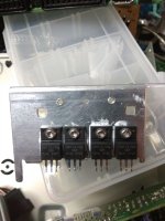
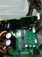
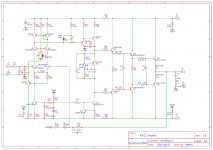
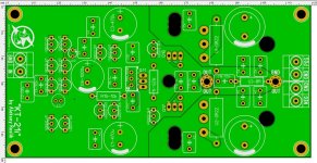
ACP+ parts kit power supply failing to start correctly

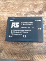
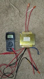
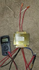
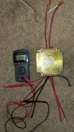
There are now a few reports in the ACP+ main thread (including mine) reporting that the included Kit 24V PSU results in a pulsating LED (and overall voltage to the system) and the unit never truly starts.

You can hear music for a second and then it "resets".

Here are some of the reports:
- https://www.diyaudio.com/forums/pass-labs/344836-amp-camp-pre-headphone-amp-acp-164.html#post6691231
- https://www.diyaudio.com/forums/pass-labs/344836-amp-camp-pre-headphone-amp-acp-164.html#post6691953
- https://www.diyaudio.com/forums/pass-labs/344836-amp-camp-pre-headphone-amp-acp-165.html#post6694615

Maybe it's worth looking into replacing the brick offered with the kit for future purchasers? Maybe there is a workaround to "kickstart" the brick?

Best regards,
Rafa.

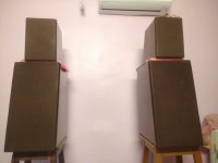
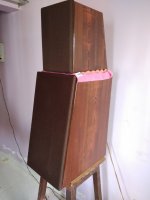
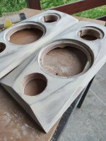
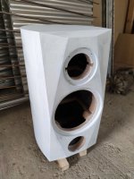
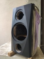
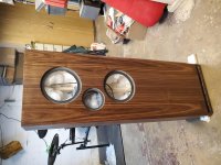
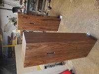
Paul Carmody's Tarkus, done finally!

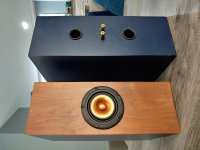
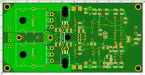
Finally finished PC's Tarkus speakers almost a year after planning on the occasion of my daughter's first birthday!.
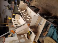
Initial PCB for mid+tweeter had a mistake which was brought to my notice by a fellow builder in India.
So had to correct the design and manufacture the pcbs again!.

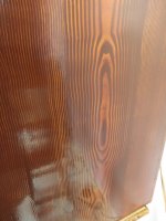
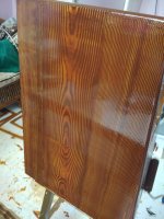
Painting took lot of time and efforts. Its horrible to work with enamel paint.

Tested them yesterday, and they do sound amazing and loud.
Still early days, will keep listening to them over the next few weeks.

Yet to fit the spikes and install them in main listening area.

regards
Prasi

Attachments

  • IMG_20190323_145502.jpg
    IMG_20190323_145502.jpg
    195.8 KB · Views: 2,129
  • IMG_20190324_022449.jpg
    IMG_20190324_022449.jpg
    392.6 KB · Views: 2,066
  • IMG_20190324_114242.jpg
    IMG_20190324_114242.jpg
    439 KB · Views: 2,121
  • IMG_20190324_114305.jpg
    IMG_20190324_114305.jpg
    624.6 KB · Views: 2,007
  • IMG-20190303-WA0000.jpg
    IMG-20190303-WA0000.jpg
    126.9 KB · Views: 1,943
  • IMG-20190303-WA0001.jpg
    IMG-20190303-WA0001.jpg
    96.2 KB · Views: 987
  • layout.png
    layout.png
    110.5 KB · Views: 938
  • sch.png
    sch.png
    23.1 KB · Views: 947

Attack/release rates for multiband limiters

Hello everyone,

I was going through the DSC-260 user manual when I noticed the following (on Page 1, Introduction)

"Output limiters to protect system transducers from overload damage with adjustable thresholds and automatic attack and release settings based on crossover frequency..."

Since the use of different attack/release rates for different frequency bands (bass, mid, treble etc.) has become commonplace, I was wondering if someone knew how to arrive at proper values for a band, based on its frequency content. Besides, it would also be nice to know of any existing methods/tables/standards for obtaining these values from the crossover frequencies.

Please note that the method(s) do not have to be scientifically proven (working methods will do). In case, anyone uses values that they've obtained otherwise (by trial & error etc.), kindly share the same.

Thank you.

(Please note that I am not in possession of the above-mentioned processor.)

Request czech users to contact Bazoš.cz

Hi anyone.

I would like to contact and buy amplifier from Bazoš.cz, but i cant get into, because i am not from Czech republic.

Is some willing to contact Bazoš user, so i could easier buy it.

For thanks, i could send quite good quality parts, modules, which also became rare and hard to find, depends of needs 😀

Thanks in advance.
Boštjan from Slovenia

Three channel stereo decoder processor reccomendation?

Hey all, i'm experimenting a bit with three-channel stereo on my next DIY speaker build. Not wanting to re-invent the wheel i was wondering if anyone out there has any recommendations for a decent surround sound decoder i could pick up used on ebay for say less than $150. I'm hoping to find electronics that attempt to create a true center channel, and left/right outputs from a standard stereo audio source. And not do the simple Center = L+R, L=L-R, R=R-L scheme often seen for simple setups. I think something like dolby pro logic II would do something like this, but to be honest that was a bit before my interest in audio and i'm having trouble understanding exactly what it's doing from reading online, and what products would be a good choice since they're a bit old now. Hoping to tap in to some knowledge here on the forum!

Just to clarify on my hopeful output of this box:
  • a mono signal (same signal on left and right channels) only comes out the center channel
  • a signal panned hard left, will only come out of the left channel (not left + center as you would get with the hafler/dynaco style center+L/R decode)

oh, and if it was able to be smaller than a full sized A/V receiver/amp combo that would be great, as I'm just after line level outs. But hey, i'll take what i can get!

thanks!!!

Pass aleph 5 amplifier

Hi I am looking for some help please.
Sorry for the long post but I am going to put as much information as I can hoping to get help.
I have a problem with my diy aleph 5 amplifier boards.
When I power up I get 30v dc at speaker terminals this drops down slowly over 10 minutes to 0.07v.
Then if I connect speakers it will play music but if I connect speakers before this they crackle loudly and blow.

I have searched this forum and found things to check bu not shure what I am looking for.
I understand these are chinese boards but was unable to find original boards anymore.
I got the boards un populated and fitted all original parts from mouser, hifi collective ,rs components and furnel.
I am using 25v/25v 500va transformers x 2 but they have no centre taps.
CRC power supply boards with 4 x 47,000 kendal capacitors and 2 x mundorf 82,000uf on each pcb.
Inputs to main boards from CRC psu boards are
+ to - 37v but this drops to 32.8v
0 to -v = -18.7v
0 to + v = +14v

My ground is through 2 x 10R 5W one for each psu channel.
IRF9610 are all matched as per nelson pass circuit but my power supply gives me 14.5v not 15v as nelson pass recommended.
IRF9610 I used are all matched to 3.59v
IRF240 are all matched to 3.69v

Voltage across 9v diode in upper IRF9610 is 8.8v
Voltage acroos 220R in upper 9610 is 4.97v
Voltage across 390R drain IRF9610 is 4.6v
DC offset at speaker is 30v on start up but drops to 0.07v over 10 minutes.

R21 453 ohm + input to R21 = 14.05v
- v input to R21 = 18.6v
0v input to R21 = - 0.37v
Wirewound 1R 5w resistors that go to right hand S pin of IRF240 I get 0.5v across all of them.

220R resistors that go to pin G left hand pin of IRF240
R9,R10,R11 left 3
R15,R16,R17 right 3

Ov to R9,R10,R11 = + 4.7v
R15,R16,R17 = -13.9v

- v from input R9,R10,R11 = +23.2v
R15,R16,R17 = -4.7v

+v input to R9,R10,R11 = +9.2v
R15,R16,R17 = -27v
Thanks for any help advice Dave

Preamp for Mic for makes high pitched noise

Hello dear forum 🙂

I am helping a friend with his Elephant-project to prevent them from getting killed my humans. So the aim is to record Elephant rumbles (which is mostly infrasound (<20Hz)) with a network of microphones, which calculates their location. (GPS collars are not really animal friendly and costly).

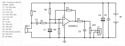
Sooo. I got this circuit which supposed to work. It's a preamp and low pass filter which attenuates frequencies above 150Hz.

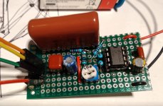
I build it and i get this high pitched noise. (Soundsample)
Unfortunately i am not smart enough with electronics to find out the reason. I used audio-grade capacitors and checked all the connections and wirings twice (but of course never 100% sure).

Where does this high pitched noise come from? What can i do to find out about it?

That would be great if someone can help me out. I am sure the elephants will thank you for it :happy1:

ED

Attachments

  • Circuit.PNG
    Circuit.PNG
    37.5 KB · Views: 291
  • prototype.jpg
    prototype.jpg
    752.6 KB · Views: 242

Help me Tweak this Simple Portable - IC amplifier

Hello Diy Audio

Im building this very simple amplifier - It is for a small sized single portable speaker,

I thought why im at it, lets try and tweak some components if its worth the experiment.... the cost is not much so who cares??

If you have any advise on what would be worth messing around with please let me know itd be interesting to play with,

I was thinking the obvious things like better resistors and a good quality volume pot, but there must be more?


-------

I have taken pics of the board for both sides, the post is further down the thread?

Attachments

  • 06052021171056-0001.pdf
    06052021171056-0001.pdf
    1.1 MB · Views: 236
  • Screen Shot 2021-05-06 at 5.20.46 pm.png
    Screen Shot 2021-05-06 at 5.20.46 pm.png
    419.3 KB · Views: 300

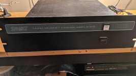
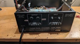
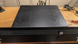
Smart Amp TA-242 (HAFLER)

Bought this amp (without Amplifier modules) years ago - it was made by Hafler and was standard install for large Theaters.

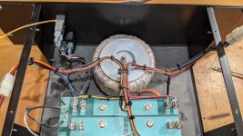
Chassis, Tranny, Rectifier and caps. Its +/- 65Vdc rails. has screw connection for speaker outs and unbalanced inputs.

More info on amp specifics...
SMART TA120 INSTALLATION AND SERVICE MANUAL Pdf Download | ManualsLib

I was going to put in a pair of ICEPower 500A modules (using just the 0 - +65v rail) and put in a additional +/- 12vdc mini smps power supply for the other required rails for the 500A....

Well, needless to say, lost interest in this project.

$80+ ship for the amp chassis as pictured.

I can throw in a couple ICEPower 500A modules for additional $65 each.

Pick up in West sub of Chicago or ship. This is HEAVY...

Attachments

  • PXL_20201214_023813629.jpg
    PXL_20201214_023813629.jpg
    748.5 KB · Views: 557
  • PXL_20201214_023539313.jpg
    PXL_20201214_023539313.jpg
    645.8 KB · Views: 508
  • PXL_20201214_023541706.jpg
    PXL_20201214_023541706.jpg
    870.2 KB · Views: 513
  • PXL_20201214_023818700.jpg
    PXL_20201214_023818700.jpg
    720.7 KB · Views: 484

Dick Olsher, TAS, First Watt F8 Review

First Watt F8 Stereo Power Amplifier - The Absolute Sound

He likes it. From his summary:

"The F8 has joined the SIT-3 on the winner's podium. These two amps offer differing but equally valid perspectives on sound reproduction. As far as current production goes, they are the two brightest stars within the First Watt family. The F8 is a reference tool in the finest sense of the words, exceptionally revealing of what comes before it in the playback chain. Its directness of expression enhances the illusion of being there, and is a function of its phenomenal clarity and transparency. These attributes should give it wide audiophile appeal."

18Sound XT1464 + 15" crossover

I'm looking at building a 2-way main with the 18 Sound XT1464 mated to a Faital HF146, crossed to a Faital 15PR400. The usage will be moderate volumes, outdoors but in a large reverberant walled yard. I'm trying to optimize the design not for SPL but for pattern control.

18 Sound has published a bare-bones design with XO at 1500Hz, looks like 2nd order slope. Is this an ideal XO from a directivity perspective? Looking at the polars it seems to be pretty good, especially to match the vertical horn pattern, but still it seems a bit high for a 15" woofer. I will be using active filters and usually go with LR4 but maybe at this XO point a 2nd order would be better?

I haven't worked with narrow pattern horns before. Anyone have experience with this combo or any advice in general?

Iron Schmitt, Concertissima & "the third" phase inverters :-)

Having read the good writings and ideas of Lynn Olson, mentioning N. Crowhurst and D.E.L. Shorter from BBC (Illusion Engines)
I have decided last year to imagine some transformer based phase inverters aiming to obtain the lowest THD possible and consequently using small amounts of negative feedback, if any. The classical phase inverter in which the primary is driven in single ended and the two secondaries are winded in phase opposition is no good for me, the THD levels are too high and the phase shifting begins at around 14-15kHz.

To the best of my knowledge the following 3 circuits are new but please feel free to correct me just in case you have seen it elsewhere. In all these circuits I have used transformers made by me, of a special/custom design, after countless hours of tests and "trial and error" attempts. "Iron Schmitt" and "Concertissima" are built around CRGO/GOSS, while the last one is built using permalloy 47% core. For the time being I can't tell more about these xfmrs but this situation can be changed in the future, we'll see...

I won't forget to thank to Bud Purvine, Pete Millet and Lynn Olson for their patience and guidance over the last decade, thank you guys!

Attachments

  • Iron Schmitt.jpg
    Iron Schmitt.jpg
    433.2 KB · Views: 829

B1 XfORmer line stage

I watched the 2017 burning amp presentation from Nelson and he showed a very minimalistic xformer based line stage that uses the 2sk170/2sj74 pair as front followed by an autoformer from cinemag! I think its the cmoq-4 output transformer. Very interesting! Has anyone build it? I guess a B1 front end would also do the job with great specs.
Any thoughts? Maybe a schematic? Thanks!

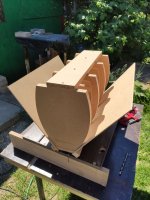
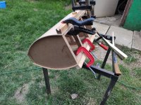
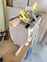
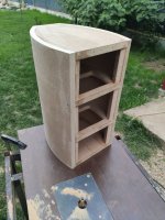
2 way SB17MFC+SB26STAC pic heavy

Hello fellows DIYers,

I have been planning for a long time to build my dream set of speakers and this time I got the time, space and resources to finally do it.
Doing a lot of research, with the goal of "best bang for the buck", I set my eyes on Jeff Bagby's TRIBUTES. For the enclosures I got some inspiration from SF and some Aliexpress clones. They will sit near the back wall so I decided to put the port on the front. They are almost ready, I'm waiting for the veneer and I'm working on the crossovers.

This is where I got so far, feel free to comment, critique, advise.

Attachments

  • 1623694389500.jpg
    1623694389500.jpg
    109.1 KB · Views: 660
  • 1623694389503.jpg
    1623694389503.jpg
    174 KB · Views: 513
  • 1623694389497.jpg
    1623694389497.jpg
    184.1 KB · Views: 470
  • 1623694389490.jpg
    1623694389490.jpg
    172.1 KB · Views: 468
  • 1623694389480.jpg
    1623694389480.jpg
    173.6 KB · Views: 484
  • 1623694389464.jpg
    1623694389464.jpg
    204.1 KB · Views: 213
  • 1623694389441.jpg
    1623694389441.jpg
    161 KB · Views: 239
  • 1623694389434.jpg
    1623694389434.jpg
    142.3 KB · Views: 270
  • 1623694389425.jpg
    1623694389425.jpg
    130.1 KB · Views: 275
  • 1623694389412.jpg
    1623694389412.jpg
    86.1 KB · Views: 385
  • Like
Reactions: audiomovil

Does anyone recognize this speaker kit??

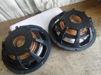
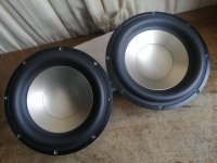
Does anyone recognize these speakers? They are home built. Maybe from a Kit?? It is VERY similar to the Seas Thor kit but with different drivers. The Tweeter is a Dynaudio D28H/2 for sure but I am not sure what the woofers are. 8” units with an inverted surround in a transmission line cabinet. Crossovers mounted in the bottom.

I bought these off craigslist and the guy that I got them from said they came from a lady he works with who got divorced and the husband left these behind. She didn’t want them and gave them to the guy I bought them from. But he had no info other than that.

Attachments

  • 20210616_141500.jpg
    20210616_141500.jpg
    798 KB · Views: 231

Measuring subwoofer at listening position

Hi all,

How would I go about to measure subwoofers at listening position? I have measuring gear (arta, focusrite scarlett, emm6 mic) and could use some tips for e.g. gating. Goal is to boost lowest-end response, take care of peaks and optimize transition to main speakers (both FR & phase), all with dsp from behringer nx3000D.

I'm running two Dayton-Audio-RSS390HO-4-15 in closed cabinets (45l), placed symmetrically behind open baffles against the front wall. That's because crossover frequency is quite high (125hz 2nd order).

Thanks in advance for any guidance 🙂

Cheers,
Simon

B1 Buffer Preamp Distortion

I am hoping to get some help with my First Watt B1 buffer preamp build. I noticed a subtle distortion that is more apparent at lower frequencies when plugged into First Watt J2 amp.

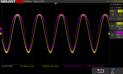
Bench test (B1 alone) is with a 1kHz sine wave at 1V. Power supply for preamp is a 24V wall wart. The findings are identical on both channels. The yellow trace is input, purple is output across a 100k Ohm load.

My questions:
1) The top part of the output wave is wider than the input signal. Is this the source of the audible distortion and can you suggest a cause or systematic approach to fix it?

2) The B1 has no voltage gain as designed, but should there be “voltage loss”? The output voltage is about half of the input.

Any help is greatly appreciated. Many thanks.

Rich

Attachments

  • SDS00003.png
    SDS00003.png
    39.8 KB · Views: 309

Question about the Quad 303 amp circuit

Hey Folks,

I'm basically a complete layman when it comes to circuitry. I have a potential concept that I've been mulling around, but had some general questions regarding the Quad 303 amp. I know the original 303 used a circuit board but I was wondering if it's possible to replicate the circuit with a mostly point-to-point wiring scheme, without using a major circuit board. This may totally be impossible, but as I mentioned, I'm quite the layman.

Here's a photo of the circuit in question:

Quad 303 circuit diagram - large copy

Attachments

  • q303cir (1).jpg
    q303cir (1).jpg
    324.4 KB · Views: 3,457

Help Please :( Marantz PM80 mkII

I've just signed up in the hope that someone here might be familiar with this amp ?

It came to me powering on but no output. My tests have shown the power amplifier board [P701] is 100% fine & B+/0v/B- is 65vdc. There is a small "regulator" board [P851] which has regulated +24v, +15v, +/-18v & unregulated 57v/0v/57v outputs. They all output the correct voltage apart from the +/-18v so I checked every component in that circuit & found five 1R resistors [R851, R852, R859, R860 & R861] were open circuit... Replaced them & tested P851 board in isolation, +/-18v now working ! Great I thought 🙄 Connected it to the preamp board [P601] and after 1 second those five 1R resistors are open circuit again.

Any clues where to look next friends ?

Service manual can be found here: Marantz PM-80 | Owners Manual, Service Manual, Schematics, Free Download | HiFi Engine

An externally hosted image should be here but it was not working when we last tested it.


An externally hosted image should be here but it was not working when we last tested it.

FS: Big Heat Sinks

Hello,

I have some heat sinks for sale.

4 pieces of Conrad (Australia) MF35-151.5.
Technical data Conrad Heatsinks - Products
Outstanding quality, 100% plan/flat from the inside

Price 45,- Euro each plus shipping.


2 pieces for huge Class A projects.
Connected with an aluminum plate, can be separated.
Size 430(215) x 220 x 82 mm
Price 55,- Euro each plus shipping.


Kind regards

Andreas

  • Locked
Sound signature

First part of Hifi construction is for me construction/diagram where I can ensure high precision via measurements and well known theory.

The second part is sound, which is mainly determined via the sound signature of components Including cables.

Here is no theory, no measurements, only experiences from many hours of listening.

My conclusion of listening is that specific materials have a sound signature, the purity of materials and Damping affect the sound, but do not remove the basic sound signature of the materials.
There is of course, a subset between the two concepts construction and sound signature

The audio signature works regardless of the component value, cable length, current, or voltage size.
The sound signature only seems to depend on the selected material, both conductive , insulating and composite materials.

My question, are there others with the same experience and are there measurements and theory that explain why copper and silver sound amazingly different in a transparent Hifi system.

Discussion is described here by Ethan Winer with his Null test, a test that doesn't fit with my experience. But I fully recognize the electrical argument he presents, and it gives me a headache.

The Null Tester - YouTube

Fullbridge D class I could not solve the problem

Is there a problem with the exact bridge site?
In the connection I made in the circle, the 4049 opposite ends are correct? Hin-Lin pins. My current problem is that the bottom 1.5k 5 watts gets too hot in a short time. Top side 1,5k 5w does not heat at all .. When the voltage divider resistors 8,2k 5 are installed, the tl071 voltage is 7 pin 6 volts between the chassis. 12 volts between 4 pin chassis. I could not figure it out. With this result, the output relay is not activated.

Attachments

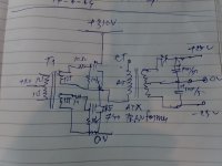
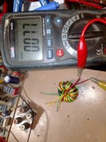
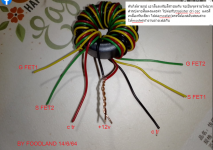
basic smps(half bridge)by foodland

basic smps It's a simple circuit suitable for beginners
The circuit consists of 1. 12v regurator for osc 55k circuit 2. b+310vdc
3. mutivibrator 55khz and gate dri trnsformer circuit
4. half bridge dri circuit

Attachments

  • IMG_20210614_022856.jpg
    IMG_20210614_022856.jpg
    614.8 KB · Views: 231
  • IMG_20210614_022652.jpg
    IMG_20210614_022652.jpg
    625.4 KB · Views: 232
  • IMG_20210614_022704.jpg
    IMG_20210614_022704.jpg
    350.7 KB · Views: 243
  • IMG_20210614_022713.jpg
    IMG_20210614_022713.jpg
    331.6 KB · Views: 239
  • IMG_20210612_184350.jpg
    IMG_20210612_184350.jpg
    566.4 KB · Views: 234
  • IMG_20210615_020737.jpg
    IMG_20210615_020737.jpg
    631.8 KB · Views: 110
  • gd1.png
    gd1.png
    495.7 KB · Views: 134
  • IMG_20210612_190335.jpg
    IMG_20210612_190335.jpg
    724.1 KB · Views: 131
  • 1623657910775.jpg
    1623657910775.jpg
    247.6 KB · Views: 125
  • 1623657886532 (1).jpg
    1623657886532 (1).jpg
    153.7 KB · Views: 121

Aline Audio pre-amp board

Some time back I purchased a preamp board using I think a PGA2311. It hs a VFD display and four inputs. My versión is V2.72, later I know there was a V2,8 with a good few changes. I cant find much with google etc and I would be glad of any help. I want to know if I can change the text on the display and if I can upgrade V2.72 to V2.8. I believe the later one had a "learn remote" feature.
Maybe Aline Audio is still about?

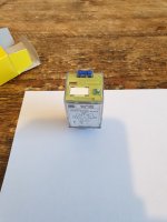
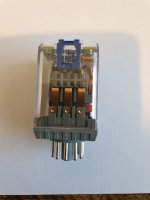
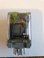
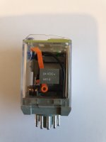
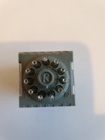
NOS 11 pin plug in relay

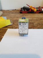
11 pin plug in relay with test button and indicators plus can be manually latched or not.
440r
24vdc
10A

£10.00 plus £2.99 postage.

Attachments

  • 20210616_120313_copy_1209x1612_1.jpg
    20210616_120313_copy_1209x1612_1.jpg
    220.4 KB · Views: 93
  • 20210616_120317_copy_1209x1612.jpg
    20210616_120317_copy_1209x1612.jpg
    256.9 KB · Views: 95
  • 20210616_120356_copy_1209x1612.jpg
    20210616_120356_copy_1209x1612.jpg
    213.1 KB · Views: 89
  • 20210616_120349_copy_1209x1612.jpg
    20210616_120349_copy_1209x1612.jpg
    226.9 KB · Views: 99
  • 20210616_120400_copy_1209x1612.jpg
    20210616_120400_copy_1209x1612.jpg
    181.2 KB · Views: 97
  • 20210616_120409_copy_1209x1612.jpg
    20210616_120409_copy_1209x1612.jpg
    146.1 KB · Views: 54

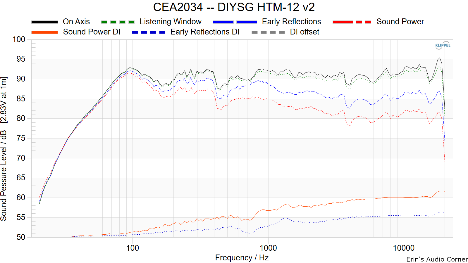
DIYSG HTM-12v2 Measurements and Review

Too much to copy/paste here, so please go to the link below for the written review and graphics.

DIYSG HTM-12v2 Speaker Review


Alternatively, you can watch the video review here:

DIYSG HTM-12v2 || High Sensitivity Home Theater Speaker on a Budget - YouTube


Cliffs: Tons of potential. A few problematic areas that would make me either not use the speaker or modify it (the latter makes the most sense, if you're already DIY'ing the speaker). As is, however, great directivity, great neutrality above about 800Hz, and great ability to be EQ'd to be more neutral. But the resonance(s) in the lower midrange need work.


DSC02006.JPG


CEA2034%20--%20DIYSG%20HTM-12%20v2.png

Measuring Operational Amplifiers DC Parameters

With this universal circuit you can measure all important op amp DC specifications.

DUT op amp with almost any unity gain frequency and with high open loop output resistance can be measured correctly!

S-Audio.Systems // Op amp DC parameters measurement

------------
As measurement example : DC parameters of NE5534 from various manufacturers

The JC2-HPA Headphone Amplifier

I stumble upon a headphone amplifier kit on Aliexpress, quite by accident. It’s based on John Curl’s JC-2 line stage circuit with an output buffer added, it costs peanuts, and it’s so attractive that keilau asked me to create its own dedicated thread. I duplicate some of the previously written stuff here to avoid all the jumping back and forth.

The original Mark Levinson JC-2 line stage is made of a complementary differential FET input stage followed by a bipolar voltage gain stage (VAS). John Curl (JC) published the schematics in the Audio Amateur in the late 70’s, but it’s not really for the DIY-ers/home builders because it requires matched unobtanium FETs. And this is the main event as far as this kit is concerned: it comes with FETs matched to… 1% in my case!

The catch? These are not the much praised 2SJ74/2SK170, but the 2SJ103/2SK246: they’re noisier, but good enough for line-level duty. I must admit the quality of the matching blew me away, so I ordered another kit to double check and as a spare.

First I was a bit reluctant to start this thread now before checking the second unit, but EUVL assured me the J103/K246 are still plentiful in China, and Weiliang, the supplier, is known for its quality work.

This will be a 4-part article, a work in progress, and a journey. What I have in mind is:
  1. Abstract (this here one)
  2. A quick start guide: what/where to buy, for those who know their stuff, minimum verbiage
  3. A bit more details on what to do, as the original kit comes with no instruction
  4. The tweaks
Disclaimer: I’m not related to any of the sellers, no way.

SB Acoustics ARA upgraded crossover design measurements

Hello everyone,

Remembered I had an account here since 2010, making my debut post now. Better late than never.

I've been researching quite a lot and have decided to invest in the SB Acoustics ARA two-way speaker design. I've owned the Buchardt S300 and was looking to upgrade to the S400 but the ARA's seem like a really good middle-ground if not on par with the S400. Anyway, I've found kits from various sites, most offering the standard crossover from SB Acoustics. Some others also offer the same crossover with upgraded parts mostly from Mundorf for a smaller price increase which I'm considering.

However, one reseller also offers a complete new crossover-design while also doing driver matching and assembly. I have no problem doing the assembly myself but this custom crossover is only offered when letting them doing the assembly. I've recieved several measurements from them which seem very good and proffessional, but since I'm no expert at reading measurements I thought I'd post them here and see if I can get some guidance in which option to go for. I work in sales myself and even though they are swearing by their upgrade I would like a second opinion.

The attached pictures and explanations are from their support/sales
/customer service. The original ARA is named "ORIGINAL" and the rest are measurements with their crossover, I hope my naming of the files and explanation of the graphs below is enough.

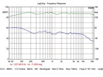
ORIGINAL: ARA on tweeter axis: green is frequency response and blue is min.phase

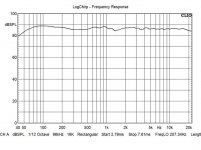
1: ARA Beryllium/SoftDome - Green/Red - they have same woofer's response, the difference is the tweeter response and off-axis response

2: Frequency (Green) and Phase (blue)

3: Tweeter axis, complex summ of gated far field, nearfield and port response

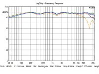
4: ARA SoftDome Off-axis: Green/Red/Ornage 0/30/45grad Horizontal, Blue/Light Blue +15/30Grad Vertical

Now for the million dollar question, add 400 Euros and get the new designed crossover or save some money and get the original, with or without upgraded components?

Thanks in advance!

Attachments

  • ORIGINALfreqResponsePhase.jpg
    ORIGINALfreqResponsePhase.jpg
    58 KB · Views: 346
  • 1- freqResponseBerylliumGreenDomeRed.jpg
    1- freqResponseBerylliumGreenDomeRed.jpg
    43.6 KB · Views: 363
  • 2 - FrequencyGreenPhaseBlue.jpg
    2 - FrequencyGreenPhaseBlue.jpg
    50.8 KB · Views: 352
  • 3 - TweeterAxisComplexSumGatedFarFieldNearfieldPortResponse.jpg
    3 - TweeterAxisComplexSumGatedFarFieldNearfieldPortResponse.jpg
    42.1 KB · Views: 334
  • 4 - OffAxisGreenRedOrange0-30-45-HorizontalBlueLightBlue15-30Vertical.jpg
    4 - OffAxisGreenRedOrange0-30-45-HorizontalBlueLightBlue15-30Vertical.jpg
    47.6 KB · Views: 331

Linn Kairn repair

Hello friends,
need some help.
I own a Kairn with a round brilliant sps that is near to die.
Its serial 1612. So it was updatet years ago from linear transformer to that round brilliant sps. I own both now, the brilliant sps(not working) and the linear kairn transformer, i want to use now.
Question: - is it possible to go back easily and set the linear psu instead of brilliant sps?
- Does anyone know the voltage on the secondary side of the linear psu? is it the same like round brilliant? Ther are loose cables on the linear psu.
- Do i have to change the rectifiers or something else?

PLEASE HELP !!

Next days i upload some pics of both psu and my fix of accu on the dislpay side

Symetrix SE400

Hello,

I am thinking of taking my Symetrix SE400 to a specialized technician to make some modifications, however, I would also like your recommendation as I want to upgrade the Op amps to better quality ones in the filter sections for a safe swap.

I know nothing about electronics and that is why I would like your help.

Basically the modifications I want to do are based on "revive audio", who have already modified these units, however it is impossible for me to do it with such company as im not in the same country.

This are the original schematics of such a unit from 35 years ago:

https://3r61fy4ckkky4bvae644ns07-wp...loads/2021/04/SE-400-Manual-and-Schematic.pdf

and these are the schematics, from an engineer who took it upon himself to make his own schematics based on the restoration he did since he could not find the originals at the time, this ones are the latest update of the schematics made by this engineer:

https://music-electronics-forum.com/filedata/fetch?id=929153&d=1618602610

https://music-electronics-forum.com/filedata/fetch?id=929154&d=1618602625


and here is possible to see the inside of the unit:

Symetrix se400 dual parametric equalizer schematic - Music Electronics Forum


I would also like to know, which modification can reduce the floor noise? would it be to change the power supply?


I hope all this information will be useful for any recommendations.


Thank you very much in advance!

Threshold circuit breaker, electromagnetic hydraulic

I'm looking for a rocker switch for a Threshold 4000 that I'm reparing.

The original part number is Heinemann JC1-A8-BB-A, but Sensata/Airpax's part no IEGX1-1-62F-14.0-02-V seems to work to.

Mouser has 7 weeks leadtime, and suppliers found at Octopart has minimum orders of 200 USD, and shipping to Sweden is as much as the cost of the switch 😱
If anyone have one spare, or are willing to help me get one in some way, I would be very happy.

Please PM me!

Best regards.

Figge

Push Pull Console Sub

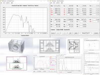
Requirements for this design are 40-120Hz, push-pull drivers with bottom front ports no more than 6" tall. Dimensions to be 41W max, up to 32" in each of the other directions. Ended up with this alignment, please critique. I'm worried about the narrow front chamber compressing only the front driver. Also, I have no idea if I'm modeling this correctly with the stepped horn sections. I had to have a smaller short front runner to fit behind the AT screen. I have another more conventional design if it is deemed that this design is not workable. TIA for feedback!

Attachments

  • da2.png
    da2.png
    301.2 KB · Views: 183

Alpair 12pw/7.3/12pw MTM

My Alpair 12pw/7.3 MarKens have been sounding great for a few years now, but I got the itch for something new over the summer. I spent a lot of time at our cabin where I have a pair of Bozak Symphonies. They have a lushness that I craved at home, without losing the accuracy and dynamics of the Alpairs. After casting about for awhile I came to the conclusion that there was no reason to get rid of the Alpairs, just add more drivers!


Enter the big MTMs from Woden/Planet 10.


While not as complicated to build as the Onkens, they weren't simple monkey coffins either. I'm happy with how the cabinets turned out, but I can't report on their sound yet. Unfortunately, I realized mid-build that one of the 12pw arrived damaged so I had to order a replacement that is taking weeks to arrive. So frustrating!


I'll run these with the same PLLXO I used with the Onkens at first, but I plan to build the passive crossover design in the paid planset. This will give me the ability to more easily play with different amps.


Stay tuned for listening impressions and test results once the new drivers arrive and are broken in.

Attachments

  • 20210212_100036.jpg
    20210212_100036.jpg
    986.3 KB · Views: 617
  • 20210212_100125.jpg
    20210212_100125.jpg
    978.4 KB · Views: 598
  • 20210130_134632.jpg
    20210130_134632.jpg
    996.8 KB · Views: 574

Problem with SVF oscillator at high frequencies

I built this Rod Elliott SVF Oscillator:-
ESP - Sinewaves

An externally hosted image should be here but it was not working when we last tested it.


The op amps are NE5532.
Supply rails are +/- 12V.
I used a J111 FET (Vgsoff = -7v) instead of 2N5484.
It works fine at lower frequencies, but I want it to operate up to 150kHz.

I made the following changes:-
VR1 = 10K (I happen to have a quality wirewound Colvern 10K dual gang pot).
R4 = R5 = 1K
C1 = C2 = 1000pF

What happens is that as the frequency approaches around 100kHz, it suddenly jumps into a state in which it oscillates between the rails at approximately 80kHz. The output is clipped. This is despite the AGC fully pinching off the FET.

It's as if there is excess positive feedback and/or unwanted phase shift at high frequencies, presumably peaking at 80kHz.

The gain-bandwidth product for an NE5532 is 10 MHz, so I did not expect problems at 150kHz.

There is plenty of supply decoupling around the op amps.
I don't think there is excessive stray capacitance or inductance with the layout.

I tried carefully matching the values for C1 and C2 using a bridge.
I tried replacing the pot with matched fixed resistors in case stray capacitance or inductance was affecting things.

I tried a different FET (an old 2N3819, Vgsoff = -5v), thinking it might be capacitance between source and drain. Initially, this seemed to help: the maximum frequency almost reaches 150kHz as the control pot is advanced. However, if you switch off and on at that setting, the oscillator still goes back to hitting the rails at around 80kHz.

I'm running out of ideas. Any suggestions?

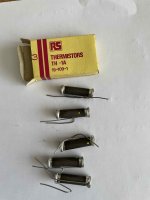
Rare NOS Brimistors

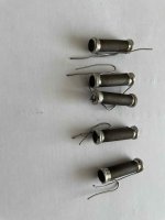
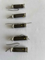
Well found these few more bits Brimistors NOS these are pretty rare now and are primarily unpolarised resistive elements of thermistor material. Uses surge suppression and resistance variation compensation for other components in amps radios TVs etc.

Used a lot in valve gear. There is a data sheet online gives you some background information.

Length 1 1/2” Diameter 7/16”.

Resistance reading at present ranging between 700-800r.

I have 5 in total so will sell as a job lot.

£20.00 plus £2.99 postage within UK

Attachments

  • 1636861E-78AC-475C-9031-8E8D3ACA253C.jpg
    1636861E-78AC-475C-9031-8E8D3ACA253C.jpg
    394.1 KB · Views: 166
  • 9D66C3B3-4B70-4921-9201-4883DA893A7B.jpg
    9D66C3B3-4B70-4921-9201-4883DA893A7B.jpg
    346.8 KB · Views: 161
  • A0D75640-722B-4217-BC5E-B2C16C70BEC0.jpg
    A0D75640-722B-4217-BC5E-B2C16C70BEC0.jpg
    349.3 KB · Views: 165

My oh my, things have become confusing--need some help

It's been many years since I have spent time on this forum. (And BTW am absolutely delighted that things are not that different--the passion and creativity is what I love--even when it boils over into a 10 page argument).

I'm in need of some help--since I was last here (maybe 2013) I have built some pretty decent sounding systems using a DEQX for xo's and correction. Well she's getting pretty long in tooth and is showing her age--mic input is dead, input jack receiver severed from board, etc. Hey nearly 20 years of service and likely tens of thousands of dollars spent on commercial systems and who knows what foo-fah in the pursuit of .... I've been a happy camper and I knew the say would come when I finally just had to suck it up, and move on. But oh my have things changed. I am just blown away by all the technology available--both in a good way, and in a whoa, I am overwhelmed as to where to even start. So I'm starting here.

My budget is in the 1000 to 1500. range--this would be for software, hardware, and a dedicated PC if needed. No qualms about buying used--the DEQX was--slightly (likely the buyer opened the manual and said bloody, no, off to Australia back you go). Thanks to the DEQX and the experience of putting together a few systems, and that I recall enough digital processing to understand what convolution is and what a bloody marvel it is, I can look through the kindle guide (M. Barnett) to Acourate, and recognize the general process of getting it do what you want.

And I am entirely willing to go down that road--I suspect never having owned an external sound card is gonna cause great pain in the beginning, so the idea of picking up a 10 year old legacy pro sound rig to save a few bucks is out of the question. Gotta have support. I'm 65 and have a finite amount of patience, and nowhere near the concentration and aptitude I once had needed to get tangled up in some jungle of technical mayhem.

So that's one option. I noticed, though, the author jumped ship after a while because of an awkward interface and lack of automation--I can totally get that (see above) and DEQX was a luxury in that regard. You could do quite a bit while never really had to get your hands dirty with all the under the hood work. So In the process, I become aware of Audiolense--looks like almost the same feature set without much of the hassle. 500 for a software suite, a solid 4/10 board (thinking another 500 or so), and I have money left over for some Dayton ice amps and get a JRiver subscription.

And that's another eye opener for a guy accustomed to a diet of Spotify and Netflix. An honestly I am still not sure what it's good for unless you have a large collection of media. Whatever else they can do is something I need to read up on.

And then today, I learn of Re-Phase, also open source that appears as powerful. Haven't read any comments plus or minus on the ease of use.

And then lastly, miniDSP seems to have grown up, and has some offerings worth considering--if Careers | The Mind Research Network (MRN) understand, the DDRC-88 is sort of a poor man's DEQX--can optimize a 4way set of drivers, crossovers, and does room tuning separately. Speaking of that, they use Dirac! I can't seem to find much about the relative strengths of the different approaches to room tuning, nor beyond ironing out the lumps in bass response, not something I've used much. A good listening area is pretty much numero uno on the priorities list when I look for a place.

So that' s the state of my ignorance--there is so much I don't know, I'm not sure even how to articulate the questions clearly. But time I do have, and if folks can point me to some useful sources, I will be all over it.


I
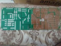
ES9038Q2M Voltage Mode DC Blocking

Hi

I'm building my first DAC using a ESS ES9038Q2M DAC in voltage mode. The outputs (balanced XLR) will be fed into a pair of KRK monitor speakers. My area of expertise is more in the digital side of things, so I was hoping someone can help me the basics of blocking the DC bias of the DAC.

In voltage mode, the DAC will output the differential voltage with an offset of 1.65V (3.3V AVVC / 2). Ideally I would like to filter out the DC bias but I'm not sure of the series capacitor value and if a resistor should be added to ground? The monitors specify 5.12KOhm balanced input impedance.

Rotel RB-1080 buying advice

I have the opportunity to buy one of these AS-IS for $200 Canadian. All I see so far is that it has a broken power connector but what I'm reading on the forums is that these tend to have some catastrophic channel problems. I've also searched the web and found a lot of mixed reviews.

What would you do with this amp as a project? I know there are some mk-II mods and some other things to stabilize them.

uc


Is it worth the time? I don't actually need the amp. Just want to give it a good home.

Thanks as always!

Technics SE HD60

I have a strange problem with this set.
Everything is good but after some time whatever is play, cd or radio, not the same every time, this go to standby.
I had a look inside the tuner and power amplifier.
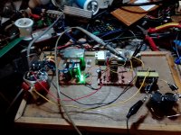
In the class D amplifier board fet aren't well pushed against heatsink but after some rework the problem not solved.
I had measure for d.c present at the output but everything is good.
Any help?

Attachments

  • IMG_20190403_174019.jpg
    IMG_20190403_174019.jpg
    452.7 KB · Views: 252
  • IMG_20190408_103857.jpg
    IMG_20190408_103857.jpg
    426.8 KB · Views: 247
  • IMG_20190408_103813.jpg
    IMG_20190408_103813.jpg
    502.6 KB · Views: 257

Is there any digital headphone amplifier with a good FFT equalizer?

Is there any reasonable digital headphone amplifier with a FFT Equalizer?

Like a 8192-point FFT or so?

I'm asking that because currently I depend heavily on the 32768-point system-wide FFT Equalizer I use on Linux to equalize sound, in particular to equalize earphones (like my JBL T110 earphones), not only because of their own crappy response but also because my ears have quite differing resonances and sensitivities (when blocked), no earphone matches properly without separate equalization.
This equalizer module treats channels separately and there's an interface, qpaeq, which I modified to allow to write and read .csv files with all coefficients.

This makes manipulating data and creating curves very easy, so if I had a portable digital amplifier with a FFT equalizer I could just use my computer to create profiles for the device, and I'd be able to equalize any signal source with it.

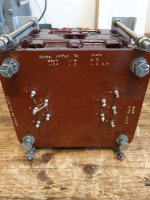
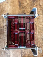
Military Sepc Large Mains Transformer

This is a large bespoke made mains transformer removed from a 300 watt military power amp.
Weighs around 8kg.
Works fine hopefully someone can find a use for it.
Only £70 plus the postage.
Specs hand written on top of transformer.

Attachments

  • 94936CE4-B30F-45DB-8611-B8296756488D.jpg
    94936CE4-B30F-45DB-8611-B8296756488D.jpg
    489.3 KB · Views: 235
  • 098F70F6-4A08-48DE-A814-9E53509C393A.jpg
    098F70F6-4A08-48DE-A814-9E53509C393A.jpg
    503 KB · Views: 241
  • 2FF5D5F2-7A78-4B27-9BAD-7E8581888E31.jpg
    2FF5D5F2-7A78-4B27-9BAD-7E8581888E31.jpg
    395.8 KB · Views: 229
  • E69BA3B3-926B-483F-B2CA-9525841B37E6.jpg
    E69BA3B3-926B-483F-B2CA-9525841B37E6.jpg
    510.4 KB · Views: 236
  • 25B3CEC5-AA0B-4545-9AFA-04D50FD08A14.jpg
    25B3CEC5-AA0B-4545-9AFA-04D50FD08A14.jpg
    459.7 KB · Views: 231

Bulb Current Limiter.Hi

Hi, would like to know if two bulbs are needed for a current limiter if both lines are live (115VAC - 115VAC). I noticed there is only one bulb connected in series with the live wire and none on the neutral side. Am in the process of making one to test my amps which have not been used for a year and a half. Our power lines are both live unlike in other countries. Thank you in advance for your advice/help on this matter.
Benzene

Bliesma T34B questions

I'm close to pulling the trigger on a pair of Bliesma T34B.

Being a fan of other large dome tweeters ie. Audax TW034 and Seas T35-C002, these may be right up my alley considering how much xmax they have to cope with a lower xover point and still play reasonably loud. The specs and measurements look impressive as does the build quality, but they are ridiculously expensive and not easy to get ahold of in the US.

Anyone have real world experience with these drivers?

What do they sound like compared to other larger diameter high end domes?

Power Trans: 36 VAC W/Center Tap @ 35 amps

Originally purchased for big SS Amp build, but went different direction. 120V primary. 36VAC CT @35 amps secondary (dual wires; see pics).
Planned to use voltage doubler to get 70VDC (+/- 35VDC @16 amps) split supply with center tap. Separate 5VAC secondary for regulation/preamp circuits.

$125 includes free ground ship to lower 48 US. 4" tall; 4.5" wide; 5.5" deep.
Thanks for looking,
Jim

Attachments

  • 1.jpg
    1.jpg
    39.4 KB · Views: 166
  • 2.jpg
    2.jpg
    83.4 KB · Views: 150
  • 3.jpg
    3.jpg
    105.7 KB · Views: 153
  • 4.jpg
    4.jpg
    100.9 KB · Views: 144
  • 5.jpg
    5.jpg
    98.2 KB · Views: 148

My 3 Month Alpair 7 MS Review. :)

I have lived with these speakers for 3 months now as my daily drivers, for general TV watching to critical listening. They sit in 0.39 cu. ft. boxes tuned to 56 hz, heavily damped with F13 wool felt. (I picked up (10) 5ft. rolls for $8 on clearance at Grainger. 🙂

What I can say about these speakers is, they are without a doubt, my favorite speakers I have ever heard, hands down. I come from a background of luxury theater design and building, and I have heard many speakers in all types of environments, and to MY ears, they are simply magic... Why magic? Because I don't understand why I love them. The line between my objectivist mindset and subjectivist by the feeling these speakers make me have is... blurred.

Science tells me, no single driver should produce vocals and kick drums at the same time. Physics tells me treble and bass should not coexist in the same unit, so on faith I went for it, and THEY FREAKING DO IT ALL.

I know the frequency response is objectively not flat, and I will get to that later, but for some initial impressions first.

Imaging is beyond anything I have ever experienced in any speaker.

In fact my father-in-law came over after I finished them and I played him Emilie-Claire Barlow's version of The Very Thought of You, and the first thing he said was "why is her voice in the middle if there's no speaker in the middle?" Exactly.

On the subject of her voice: Female vocals and stringed instruments especially shine best out of the genres I have played. Mids are GORGEOUS. Spare the fancy terms. Sweet Love of Mine by Joy Williams and Teir Abhaile Riu by Celtic Woman are absolute gold from the Alpairs. Wind instruments as well have such a beautiful quality. When it comes to Drum & Bass, Dubstep, or anything with heavy amounts of bass, they tend to... Run out of steam? I don't know how to concisely describe what happens. They DO play fine, but cohesion is understandably lost with higher excursion loads.

Initially in a room measuring approx. 14' x 20' x 8' with with weird shapes and moderate damping, imaging was best but bass was lacking. Quick measurements put us at steep drop off below 70hz or so. And then I moved them to a moderately damped 12' x 13' x 8' room, where I could make use of some wall boundaries, and NOW we have bass. Center image became a bit muddy, listening from about 9' back, however we now have absolutely sufficient bass down to, I would guess the low 50's with what feels like a much more shallow rolloff. No measurements. Toe-in aided the center focus.

In this same room I decided to run them as nearfield computer speakers and that's where I got to experience the main downsides of these speakers.

Being so close to them, the treble is very apparent and at high volumes, I was becoming fatigued much quicker than anything else I've heard before. I'd have to blame that 12kHz peak for that. Just not flat enough for my liking. And that is really my only big gripe with these. Toe-ing them out a bit solves that but we lose the imaging magic as well. I personally prefer them as a mid to farfield speaker than nearfield, in a small to medium room. A/B-ing these against my TABAQ RS-100 2-ways with 5/8" Dayton tweeters, I can admit to liking the treble a whole lot more than the Alpairs.

My other problem with these, is a cosmetic thing: the center cap. On both of my units, the overall build quality is fantastic aside from massive glue beads around each center cap. It really does not look good.

So in total, they are not for everybody, and they aren't for ultra loud listening, or for multiple seating environments like a theater because I could hear the beaming and treble is destroyed off-axis.

I know they measure poorly on a scale, and I have a deep respect for objective measurements and science in the audio world, especially being in a work field involving so much physics and acoustical engineering. But I can't shake these drivers. I was set when I got them to prove myself right in knowing they'd sound bad... But guess what? They just... Make me happy. And at the end of the day, that's all that matters.

Do with that what you will. 😛

Attachments

  • 20210312_225004_HDR.jpg
    20210312_225004_HDR.jpg
    982.2 KB · Views: 715
  • 20210312_225153_HDR.jpg
    20210312_225153_HDR.jpg
    1,003.9 KB · Views: 651
  • Like
Reactions: infected and hmj

Mixing Class D with AB?

Hi,

I'm using 3 class AB amps for my horn speaker system (two way+subs) and I need another one to eq every sub individually. Summer is already here more or less and temperatures rising... So I thought about buying the Behringer A800 for my subs. It would be two Class AB amps for the tweeter and midbass and two A800 for the subs. Do you think this is a bad idea soundwise? Or no problem at all?

I'm not sure if the A800 is good for high sensitivity speaker. I read that the mids and highs are hollow or clinical. But for the subs this shouldn't be a problem. I want to save some power and heat.

Did I Lose an Output Transformer?

I've been running a pair of Dynaco 70s with the VTA boards in a vertical bi-amp configuration for about 15 months now, and have loved the result. Today, I heard a slight fizzing sound from the left side for a second or two, then it seemed to settle down and play ok. Within a few minutes, the left side was notably distorting, and eventually stopped making sound.

I've narrowed the issue to one channel of the left side amp that was driving the mids/tweeters, and am wondering if I've lost an output transformer. I've switched tubes around, and the issue stays with that same channel. I've removed the tubes from the bad channel, and reconnected the mids/tweeters with the woofer channel of the problematic amp, and am getting good sound from it, but that side is no longer bi-amped.

Any suggestions for what might be wrong, or logical next steps to help trace the problem?

Is a single capacitor psu possible

Hi thanks for reading.

I built a simple psu for my amplifier consisting of a 12v 15 amp transformer, followed by a bridge rectifier, then a 47,000 uf cap.
There was a lot of noise coming through the speaker so i inserted another 47,000uf and the noise went down. I kept inserting caps, the noise kept lowering, until i reached 135,000 uf and the noise disappeared completly.
I figured 135,000 uf was the perfect value so i took out the six caps and replaced with a single 150,000uf cap which is the closest value i could find, but some of the noise came back.
Why is that. Is it because the first cap smoothed the ac from the bridge rectifier, the second cap smoothed a little more, until it reached the sixth cap and was further smoothed to clean out the ripple totally, something a single cap cannot do.
Or is it the six caps being paralled connected had lower esr esl values which aided the smoothing process.
From this is it possible to build a power supply with just one smoothing cap or is this going too far.

Thanks.

Hifonics bxi 12000d

I got this hifonics with some output fets blown. Repaired doughter board. Drive board seems OK, and is buffered. On one side I don't get a signal, even no voltage.

One side is negative, the other side has only positive rail voltage. Black probe at sec center. Rail voltage are ok.. Maybe someone has an advice

Attachments

  • IMG_20210613_155323.jpg
    IMG_20210613_155323.jpg
    702.2 KB · Views: 146
  • IMG_20210613_155328.jpg
    IMG_20210613_155328.jpg
    780.3 KB · Views: 139

Is it possible to get lossless from Apple TV 4k to an external dac?

When the Apple TV is connected to the TV via HDMI the tv limits max audio bitrate to 24/48khz. I’m thinking of getting a hdmi switch with an optical out, but I think the tv will still limit the max bitrate output of the apple tv to 48khz. Anybody know if it’s possible to get lossless audio from apple tv 4k to an external dac? Thanks.

Snubbing capacitors

Hi Thanks for reading. I am having a problem with psu noise and am wanting to use snubbing caps to try out and see if it helps reduce all the buzzing noise i am getting.


Are there any packaged bridge rectifiers, or types of diodes, that are less vunerable to this noise, what would you recommend.

What size caps and resistors ( ohms and power handling ) would you recommend for snubbing.


I have a few packaged bridge rectifiers, how should the caps be soldered on to the lug terminals, is a diagram possible.

Thanks

Graph comparison, which one is the best?

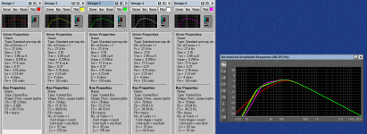
This is my FIRST-TIME experience with bass-reflex design. I, in fact, usually get used to closed box design. Also, this is my first-time using computer-aided design; a BassBox 6 Pro.

I've created 5 designs. I need a hand on help select choice which one is the best, in your opinions. The driver is JBL LC-S1250W. Parameter of the driver is shown in pics.

Design 1: Closed box, 85L, Q = 0.41 (Actually, in calculation, I intended to set it at 0.5, but the program said it is 0.41)
Design 2: Vented box, 78L, Vent diameter = 5.7 cm., Vent length = 17.8 cm.
Design 3: Vented box, 78L, Vent diameter = 6.5 cm., Vent length = 19.5 cm.
Design 4: Vented box, 78L, Vent diameter = 5.7 cm., Vent length = 6.49 cm.
Design 5: Vented box, 78L, Vent diameter = 6.5 cm., Vent length = 9.1 cm.

For the reason of Vb of vented boxes were 78L because I tried to use a Keele & Hoge alignment which said to be equal to Bessel alignment with Ql = 3, but I'm not sure if my understanding is correct.

I'd love to hear any comments and suggestions. Thank you in advance.

Attachments

  • curves.png
    curves.png
    113.2 KB · Views: 368

Problem with an Hiraga amp.

Hi All,

I have a Jims audio Hiraga amplifier I built a couple of years ago.
Wonderful amp. Runs daily in my main system. Love it.

But it has a problem in ONE channel.
The gain in that channel drops occasionally. If I disconnect the input RCA’s and cycle the power switch it comes good. Works fine. Usually for the rest of the day. Been putting up with the problem for at least a year. Amp is so good otherwise I just live with this issue.

I have an electronics tech background. I’ve replaced many components, but not all, on the board to no avail. Checked and resoldered all joints.

I strongly suspect that this channel is getting parasitic oscillations. It’s unstable at high frequencies. Possibly MHz. It never happens to the other channel. I’ve swapped the boards left and right and the fault follows the suspect board.
Both boards use the SAME plus / minus power supply. Both rails are regulated.

If anyone would know what to do with this board it could be you guys on diyaudio. So I finally thought to ask? Could there be some component slightly out of spec on that board that is not stopping positive oscillations like the other board which doesn’t have the problem? Or is there a harmless remedy?

Any help appreciated.

Regards,
Paul.

MarkAudio surround “Tripole” speakers

Dear all,
I will soon be making a pair of speakers with the new MarkAudio A11MS drivers & id like to also make a pair of matching side surround speakers.

For many years, I have used M&K sound “tripole” surround speakers, these use a mid/tweeter on the front with 3” drivers on the sides firing fore (in phase) & aft (out of phase).

I’d really like to copy this design, I’ll probably use the same A11MS on the front & a smaller/cheaper model on the sides.

What model would you guys recommend to use on the sides & how would one wire these up ?

Many thanks guys
Jason
Projects by fanatics, for fanatics
Get answers and advice for everyone wanting to learn the art of audio.
Join the Community
507,714
Members
7,885,588
Messages

Filter

Forum Statistics

Threads
406,105
Messages
7,885,588
Members
507,714
Latest member
sjun1019