Hi I am looking for some help please.
Sorry for the long post but I am going to put as much information as I can hoping to get help.
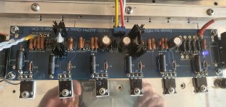
I have a problem with my diy aleph 5 amplifier boards.
When I power up I get 30v dc at speaker terminals this drops down slowly over 10 minutes to 0.07v.
Then if I connect speakers it will play music but if I connect speakers before this they crackle loudly and blow.
I have searched this forum and found things to check bu not shure what I am looking for.
I understand these are chinese boards but was unable to find original boards anymore.
I got the boards un populated and fitted all original parts from mouser, hifi collective ,rs components and furnel.
I am using 25v/25v 500va transformers x 2 but they have no centre taps.
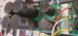
CRC power supply boards with 4 x 47,000 kendal capacitors and 2 x mundorf 82,000uf on each pcb.
Inputs to main boards from CRC psu boards are
+ to - 37v but this drops to 32.8v
0 to -v = -18.7v
0 to + v = +14v
My ground is through 2 x 10R 5W one for each psu channel.
IRF9610 are all matched as per nelson pass circuit but my power supply gives me 14.5v not 15v as nelson pass recommended.
IRF9610 I used are all matched to 3.59v
IRF240 are all matched to 3.69v
Voltage across 9v diode in upper IRF9610 is 8.8v
Voltage acroos 220R in upper 9610 is 4.97v
Voltage across 390R drain IRF9610 is 4.6v
DC offset at speaker is 30v on start up but drops to 0.07v over 10 minutes.
R21 453 ohm + input to R21 = 14.05v
- v input to R21 = 18.6v
0v input to R21 = - 0.37v
Wirewound 1R 5w resistors that go to right hand S pin of IRF240 I get 0.5v across all of them.
220R resistors that go to pin G left hand pin of IRF240
R9,R10,R11 left 3
R15,R16,R17 right 3
Ov to R9,R10,R11 = + 4.7v
R15,R16,R17 = -13.9v
- v from input R9,R10,R11 = +23.2v
R15,R16,R17 = -4.7v
+v input to R9,R10,R11 = +9.2v
R15,R16,R17 = -27v
Thanks for any help advice Dave
Sorry for the long post but I am going to put as much information as I can hoping to get help.
I have a problem with my diy aleph 5 amplifier boards.
When I power up I get 30v dc at speaker terminals this drops down slowly over 10 minutes to 0.07v.
Then if I connect speakers it will play music but if I connect speakers before this they crackle loudly and blow.
I have searched this forum and found things to check bu not shure what I am looking for.
I understand these are chinese boards but was unable to find original boards anymore.
I got the boards un populated and fitted all original parts from mouser, hifi collective ,rs components and furnel.
I am using 25v/25v 500va transformers x 2 but they have no centre taps.
CRC power supply boards with 4 x 47,000 kendal capacitors and 2 x mundorf 82,000uf on each pcb.
Inputs to main boards from CRC psu boards are
+ to - 37v but this drops to 32.8v
0 to -v = -18.7v
0 to + v = +14v
My ground is through 2 x 10R 5W one for each psu channel.
IRF9610 are all matched as per nelson pass circuit but my power supply gives me 14.5v not 15v as nelson pass recommended.
IRF9610 I used are all matched to 3.59v
IRF240 are all matched to 3.69v
Voltage across 9v diode in upper IRF9610 is 8.8v
Voltage acroos 220R in upper 9610 is 4.97v
Voltage across 390R drain IRF9610 is 4.6v
DC offset at speaker is 30v on start up but drops to 0.07v over 10 minutes.
R21 453 ohm + input to R21 = 14.05v
- v input to R21 = 18.6v
0v input to R21 = - 0.37v
Wirewound 1R 5w resistors that go to right hand S pin of IRF240 I get 0.5v across all of them.
220R resistors that go to pin G left hand pin of IRF240
R9,R10,R11 left 3
R15,R16,R17 right 3
Ov to R9,R10,R11 = + 4.7v
R15,R16,R17 = -13.9v
- v from input R9,R10,R11 = +23.2v
R15,R16,R17 = -4.7v
+v input to R9,R10,R11 = +9.2v
R15,R16,R17 = -27v
Thanks for any help advice Dave
one diode is in wrong orientation
Thank you I will have to find which one it is must be marked wrongly on pcb.
one diode is in wrong orientation
Hi adason I have tested all diodes and they are correct way round according to aleph 5 circuit diagram.
Diode D1 shows 0.638 in one direction and 1.596 in other.
I thought it might be a faulty diode so removed it tested it and it tested ok out of circuit.
I fitted a new diode but same readings.
Disconected 0v ground from psu and diode now shows 0.638 one direction and 0 in other.
Does this mean my CRC power supply boards are faulty or could it be that boards say 15,000 uf capacitors and I am using 47,000uf capacitors.
Last edited:
The use of 47k uF caps is not the cause of your problem.
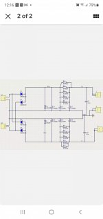
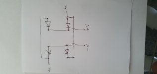
Please have a look at your schematics against something like this and trace the
4 diodes:
https://qph.fs.quoracdn.net/main-qimg-225584e3f63ba8b4033f354824101c08
You also mentioned you have two 25V secondaries. So you need to check the wiring
diagram of your transformer so that the wires going to in1_2 and in2_1 when tied together
forms a centre tap.
Last edited:
simple as this:
you have too much problems and not enough experience to solve them:
A. xformers without center tap :
-- you need other solution than resistors to obtain proper GND; one solution is - look at Quad 606 and 909 schematics how to do that, but only as guidance - here that need to be done with greater power transistors, due to uneven loading of rails with specific Aleph circuit; if you don't understand how from mentioned schematics, you're in trouble
-- you said "xformers"; with few more Graetz bridges, you can get one 35Vdc rail per xformer, then combine them properly to get real +/-35Vdc PSU
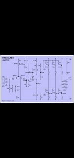
B. to us unknown pcbs; how to decipher that, when attached schm is from KK site, and who knows is there any correlation between pcb parts nomenclature and schm parts nomenclature?
without enough mileage in electronics, making too much compromises in start - results only in trouble
proper way of starting new amp build is - ask for help here to get all parts properly ( pcbs and PSU and everything else), instead of crying for help later
not judging or criticizing, just saying what is right way, leading to much less headache
so - you need to resolve PSU first; explain arrangement of your xformers - how many of them, how many cases ( one chassis, or monoblocks )
it will be best that these (hopefully two) xformers are in same case, so you can have proper +/- PSU with them
you have too much problems and not enough experience to solve them:
A. xformers without center tap :
-- you need other solution than resistors to obtain proper GND; one solution is - look at Quad 606 and 909 schematics how to do that, but only as guidance - here that need to be done with greater power transistors, due to uneven loading of rails with specific Aleph circuit; if you don't understand how from mentioned schematics, you're in trouble
-- you said "xformers"; with few more Graetz bridges, you can get one 35Vdc rail per xformer, then combine them properly to get real +/-35Vdc PSU
B. to us unknown pcbs; how to decipher that, when attached schm is from KK site, and who knows is there any correlation between pcb parts nomenclature and schm parts nomenclature?
without enough mileage in electronics, making too much compromises in start - results only in trouble
proper way of starting new amp build is - ask for help here to get all parts properly ( pcbs and PSU and everything else), instead of crying for help later
not judging or criticizing, just saying what is right way, leading to much less headache
so - you need to resolve PSU first; explain arrangement of your xformers - how many of them, how many cases ( one chassis, or monoblocks )
it will be best that these (hopefully two) xformers are in same case, so you can have proper +/- PSU with them
Thanks zen mod I will get some more transformers probably 2 x 0- 12 / 0-12v use the 0 as centre tap to give me 24v.
Made a krell ksa50 power amp that worked really well also made a valve dac from lampizator years ago still got that and it sounds really good.
Done my city and guilds many years ago as a electrician spent most of my years as a vending engineer fixing coffee machines so completely different from amplifiers.
My transformers are 1 x 0-25v at 500va I have 2 of them.
They was really cheap from ebay thought I was saving myself a few £.
I just needed a project to stop me going mad as I am stuck at home to ill to work & enjoy hifi.
hold your horses, do not buy anything ;
first:
first:
explain arrangement of your xformers - how many of them, how many cases ( one chassis, or monoblocks )
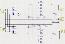
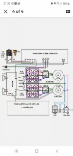
This is the circuit they sent me with the boards for power supply but see them other psu boards on ebay saying for pass amplifier.
I am not happy with them transformers anyway because they buzz even without anything conected to the outputs.
I am not happy with them transformers anyway because they buzz even without anything conected to the outputs.
Attachments
- Home
- Amplifiers
- Pass Labs
- Pass aleph 5 amplifier