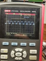
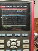
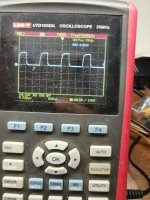
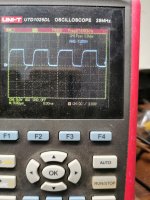
What does the drive signal look like at the gates of the FETs?
JL, in the 500/1 and likely in this amp, used a parallel resistor and diode and a capacitor to generate deadtime. It's rare that there is a problem there. I'd expect the problem to be in the drive circuit nearer the outputs.
JL, in the 500/1 and likely in this amp, used a parallel resistor and diode and a capacitor to generate deadtime. It's rare that there is a problem there. I'd expect the problem to be in the drive circuit nearer the outputs.
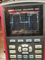
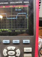
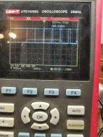
It's possibly triggering but with the signal, it's being modulated so it looks blurred.
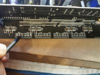
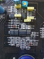
There is a 555 timer and LM319 together. Find the terminal of the LM319 that has the signal from the output of the 555. The other input of that 1/2 of the 319 is driven by an op-amp. Which op-amp is it? It should be in that general area.
There is a 555 timer and LM319 together. Find the terminal of the LM319 that has the signal from the output of the 555. The other input of that 1/2 of the 319 is driven by an op-amp. Which op-amp is it? It should be in that general area.
It would be more definitive with the FETs in the circuit (no rectifier) so that the drive circuit had a load.
I don't know if it works with this amp but the 500/1 would give a drive circuit if you pulsed remote for a second. The 500 gives about 15 seconds of driver supply voltage after remote is removed. The main supply has a delay.
I don't know if it works with this amp but the 500/1 would give a drive circuit if you pulsed remote for a second. The 500 gives about 15 seconds of driver supply voltage after remote is removed. The main supply has a delay.
Last edited:
- Home
- General Interest
- Car Audio
- JL Audio G-MAX 1200 Replacement part