Having read the good writings and ideas of Lynn Olson, mentioning N. Crowhurst and D.E.L. Shorter from BBC (Illusion Engines)
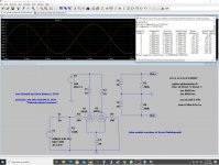
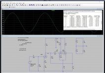
I have decided last year to imagine some transformer based phase inverters aiming to obtain the lowest THD possible and consequently using small amounts of negative feedback, if any. The classical phase inverter in which the primary is driven in single ended and the two secondaries are winded in phase opposition is no good for me, the THD levels are too high and the phase shifting begins at around 14-15kHz.
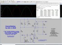
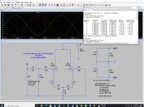
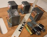
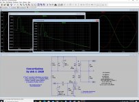
To the best of my knowledge the following 3 circuits are new but please feel free to correct me just in case you have seen it elsewhere. In all these circuits I have used transformers made by me, of a special/custom design, after countless hours of tests and "trial and error" attempts. "Iron Schmitt" and "Concertissima" are built around CRGO/GOSS, while the last one is built using permalloy 47% core. For the time being I can't tell more about these xfmrs but this situation can be changed in the future, we'll see...
I won't forget to thank to Bud Purvine, Pete Millet and Lynn Olson for their patience and guidance over the last decade, thank you guys!
I have decided last year to imagine some transformer based phase inverters aiming to obtain the lowest THD possible and consequently using small amounts of negative feedback, if any. The classical phase inverter in which the primary is driven in single ended and the two secondaries are winded in phase opposition is no good for me, the THD levels are too high and the phase shifting begins at around 14-15kHz.
To the best of my knowledge the following 3 circuits are new but please feel free to correct me just in case you have seen it elsewhere. In all these circuits I have used transformers made by me, of a special/custom design, after countless hours of tests and "trial and error" attempts. "Iron Schmitt" and "Concertissima" are built around CRGO/GOSS, while the last one is built using permalloy 47% core. For the time being I can't tell more about these xfmrs but this situation can be changed in the future, we'll see...
I won't forget to thank to Bud Purvine, Pete Millet and Lynn Olson for their patience and guidance over the last decade, thank you guys!
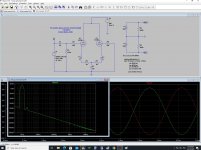
Attachments
The classical phase inverter in which the primary is driven in single ended and the two secondaries are winded in phase opposition is no good for me, the THD levels are too high and the phase shifting begins at around 14-15kHz.
The output stage is the main source of THD, so what is the point to reach 0.05% at phase inverter when the output tubes generate 2...5%?
The output stage is the main source of THD, so what is the point to reach 0.05% at phase inverter when the output tubes generate 2...5%?
If you use ultralinear or triode mode the THD isn't so high... but you have a good point, nonetheless.
Now, try to imagine a PP using "Iron Schmitt" and 6AS7 as final tube... this tube has a healthy region in A2.
What you've shown to us here are just phase inverters with transformer coupling to the next stage, as phase inversion still happens with the tubes. Anyway, due to the transformers' relatively small primary DC resistance when compared to conventional designs, higher signal swings are possible especially with your Iron Schmitt and your totem pole (I'd not call them similarly with Concertina). I'm not sure about that with your 3rd design, though.
Best regards!
Best regards!
What you've shown to us here are just phase inverters with transformer coupling to the next stage, as phase inversion still happens with the tubes. Anyway, due to the transformers' relatively small primary DC resistance when compared to conventional designs, higher signal swings are possible especially with your Iron Schmitt and your totem pole (I'd not call them similarly with Concertina). I'm not sure about that with your 3rd design, though.
Best regards")
Attachments
Last edited:
Hi Dorin,
Have you considered a MOSFET Concertina for testing / comparison? THD can be quite low, I tried...
Regards, Gerrit
Not yet, I doubt it will work in A2 (AB2) capacitors coupled. I also try to use less sand (silicon)
. This can change too in the future, nonetheless.Best regards
I am interested in Geloso amplifiers, which use a driver transformer for AB2 operation of 807 output tubes ...
geloso G-274-a
Is this in the same vein as your thinking?
geloso G-274-a
Is this in the same vein as your thinking?
I am interested in Geloso amplifiers, which use a driver transformer for AB2 operation of 807 output tubes ...
geloso G-274-a
Is this in the same vein as your thinking?
No, this is the one that doesn't perform too well, natively. I'm talking about the circuit, mostly, too much THD and phase shifting behaviour regardless of the quality of the xfmr
Having read the good writings and ideas of Lynn Olson, mentioning N. Crowhurst and D.E.L. Shorter from BBC (Illusion Engines)
The classical phase inverter in which the primary is driven in single ended and the two secondaries are winded in phase opposition is no good for me, the THD levels are too high and the phase shifting begins at around 14-15kHz.
Could Bud not come up with something decent? I mean the 1950s phase inverter transformers I am using do 15Hz-30KHz within 1dB and have a max output at 30Hz of 2x 50Vrms. 10K to 2x 100K.
Edit: these are AC-coupled (no DC through the primary). Besides that, is a 14KHz phase shift noticeable? When reversing the polarity of my tweeter I can hear no difference.
Last edited:
Could Bud not come up with something decent? I mean the 1950s phase inverter transformers I am using do 15Hz-30KHz within 1dB and have a max output at 30Hz of 2x 50Vrms. 10K to 2x 100K.
Edit: these are AC-coupled (no DC through the primary). Besides that, is a 14KHz phase shift noticeable? When reversing the polarity of my tweeter I can hear no difference.
"Decent" is a good choice of word, I'm aiming a little higher, by circuit design. If you ask Bud he'll tell you that classical interstages 70-80 years ago can be improved employing new, better materials, but not 2-3 times better.
For the specs you mentioned that IT transformer should have at least 40-50H in primary and 2x400-500H in secondaries... this is hard enough to achieve. I've done it, but as I said, I've obtained much better results with my new circuits.
I've not mentioned yet but my interstages have rigorously same Rdc for corresponding windings, obtained using a hybrid winding technique, proprietary in fact.
Best regards
- Home
- Amplifiers
- Tubes / Valves
- Iron Schmitt, Concertissima & "the third" phase inverters :-)