Nothing is missing, L5 is an audio choke built after "parafeed" rules, meaning minimal capacitances. It can be avoided with the disadvantage of complicating the circuit a little but is not worth it because THD will be anyway higher w/o choke. I have tested both variants.
Yes BUT is the L5 a part of same ransfprmer core or it is a separate core, additional core choke?
And what unit values of inductances in [mHy] or [Hy] ?
Coupling factor is pretty close to 1 so that implicates small Ls and small capacitances?
I think the main issue is topology and construction of the complicated transformer... Core materials is from vital importance and layers with insulation.
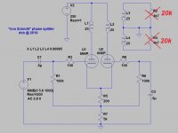
See "k" directive for all 3 cases, that will indicate when L5 is standalone, in this exposé Concertissima... the "k" directive is anyway not fair with a complex transformer because certain windings can have higher coupling factor.
In my endevour regarding these phase splitters I didn't use sim machine as primary tool but more to ilustrate the already made circuit. There are anyway better simulation programs than LTSpice out-there but I prefered to invest my time in real tests instead of learning elusive chunks of software.
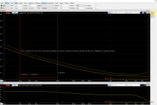
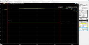
Regarding the bandwidth response (phase will mimic closely) have a look of an earlier test (last year) using 6N1P at 8mA per branch. That particular xfmr was designed for higher currents as for 6N6P, with max currents 25-30mA. It is an early test of Iron Schmitt, to be precise.
Later edit: Inductances are in "H" (Henry), LTSpice default.
The bad news is that an off-the-shelf 4 windings classical interstage xfmr won't perform at full potential with these circuits, I have tried.
Attachments

Last edited:
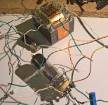
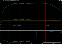
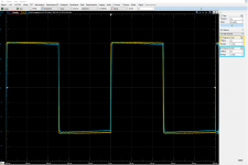
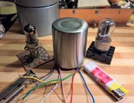
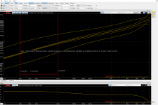
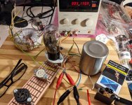
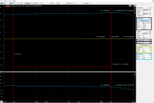
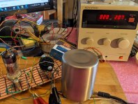
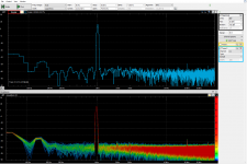
More on bandwidth and phase response see measurements made with a real circuit, another Iron Schmitt variation with no choke (last year, no ZOBEL or other tight optimization - as you can see the test circuit lays on the workbench).
Quick tests with Digilent's Analog Discovery this time, real tests...
The tube used was 6N6P (ECC99/E182CC), 15mA per branch, 2x20k load (very nasty load, I would say...);
- 20Hz-20kHz at -0.8dB
- 6Hz-113kHz at -3dB ...
Quick tests with Digilent's Analog Discovery this time, real tests...
The tube used was 6N6P (ECC99/E182CC), 15mA per branch, 2x20k load (very nasty load, I would say...);
- 20Hz-20kHz at -0.8dB
- 6Hz-113kHz at -3dB ...
Attachments
Last edited:
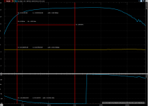
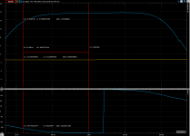
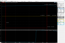
... and now see measurements of a classical SE-PP interstage xfmr of a very good quality, both signals
... if it wasn't too clear what I was trying to say so far... 🙂
.
... if it wasn't too clear what I was trying to say so far... 🙂
.
Attachments

Last edited:
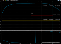
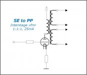
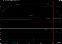
Just a preliminary test of a newly designed 20 mA interstage for "Iron Schmitt" and "Concertissima". Here in single ended (primaries and secondaries in series - generator/oscilloscope), variable source impedance 600Ω, 10kΩ and 20kΩ, no DC.
More on this next week, I hope... 🙂
More on this next week, I hope... 🙂
Attachments


Is this transformer serial connected really 30k and 240H ?
At what voltage is this 60Hy/wdg measured?
At what voltage is this 60Hy/wdg measured?
Last edited:
Never used one of those, pointless spec:THD+Noise <0.05% @ 1K Hz.
Any transformer will have something like that at 1kHz.
Would be more impressed by 10 times of that distortion at full blow and frequency extremes.
Any transformer will have something like that at 1kHz.
Would be more impressed by 10 times of that distortion at full blow and frequency extremes.
Is this transformer serial connected really 30k and 240H ?
At what voltage is this 60Hy/wdg measured?
The measurements are made at 5V, for each winding, as specified in the first drawing, and yes, with primaries (or secondaries) in series should give something like 30K/240H, like below. The previous xfmrs at the begining of the page had these specs in half, mainly due to the higher current, 35mA
I guess these are more for educational purposes and won't work anyway for "Concertissima"
Attachments
Last edited:
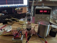
Here's a simple audio test with my new interstage xfmr IS1111IS20 ( designed for PP phase splitter "Iron Schmitt" ) under DC imbalance at 3mA using a type 26 TungSol triode - still performs more than decently in SE, 15Hz-115kHz @ -3dB
Attachments
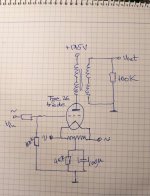
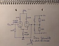
... and here you have the circuit this xfmr was designed for, well, there are better tubes than 6SN7 but this is good as example... No Zobel networks, no beauty tweaks whatsoever... just raw results to prove the concept 🙂
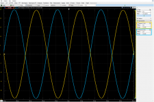
Sinewaves 20Hz and 30kHz, sweep 10Hz-200kHz
Sinewaves 20Hz and 30kHz, sweep 10Hz-200kHz
Attachments

Last edited:
Hi Dorin,
In your post 32, is the interstage transformer dedicated for SE to PP use, where supposedly the ground tap should be between the two secondary halves? This is a bit of a teasing question, due to the difficulty of SE to PP interstage transformer design 🙂
In your post 32, is the interstage transformer dedicated for SE to PP use, where supposedly the ground tap should be between the two secondary halves? This is a bit of a teasing question, due to the difficulty of SE to PP interstage transformer design 🙂
Hi Dorin,
In your post 32, is the interstage transformer dedicated for SE to PP use, where supposedly the ground tap should be between the two secondary halves? This is a bit of a teasing question, due to the difficulty of SE to PP interstage transformer design 🙂
There's no rule here, no designated ground tap.
So technically inside it's a SE:SE transformer, and the PP conversion is done by a virtual tap or something?
So technically inside it's a SE:SE transformer, and the PP conversion is done by a virtual tap or something?
Yes, you are right, now it has about 5mA DC capability in SE, which is more than generous in the case that difference between triodes occurs in the "Iron Schmitt" circuit. I can easily increase the airgap to obtain about 20-25mA DC capability in SE but this is not what I'm after right now... which is setting a foundation for PP amplifiers all the way to AB2 class with minimal feedback, if any...
Last edited:
Thanks! Good luck with your projects!
Same to you, good luck!
I've been asked about the phase response, here are the two outputs, + and -, with same 16 degrees deviation 20Hz-20kHz
Attachments
I've played further with the xfmr developed starting at post #26 increasing the DC capability to 20mA, using 6E6P in triode mode. Here's the response with a 100mVrms input signal, results in a 3.6Vrms output, with a decent cvasi-non existing THD...
Attachments


Last edited:
- Home
- Amplifiers
- Tubes / Valves
- Iron Schmitt, Concertissima & "the third" phase inverters :-)