FS: Seas Nextel W18NX001 unit (1 piece)

I have for sale one (1+ 1) Seas Nextel W18NX001 unit. Unit was lightly used for few years and it is in perfect mechanical and electrical shape. The metal plug is nickel chrome polished (new versions has a bit different finish). Original packing included.


Price is 90 EUR + post costs. Payment via PP.

Attachments

  • img_20210215_193353 (1).jpg
    img_20210215_193353 (1).jpg
    391.7 KB · Views: 380

Yamaha A-1 idle current issue

Hello, any Yamaha A-1 DC coupled specialists out there?


This amp is ‘working’ but Idle Current won’t adjust at all with newly installed Bourns trimpots and is at 1000mV on one channel, 0 mV on the other!

So far, I’ve:
replaced all OT’s with MJ21193/4G
replaced four 330ohm resistors at R 101, 102, 103, 104 with https://uk.farnell.com/multicomp/mf12-330r/res-330r-1-125mw-axial-metal-film/dp/9343032
replaced two fusistors at FR 101, 102 with https://uk.farnell.com/koa-speer-el...-film/dp/3541480?CMP=e-email-sys-orderack-GLB
Are the above replacements all correct?

A hum is present.

Readings:
-DC is 35 V and stable
-Offset DC is 0 mV and ranges +/- 5mV.

DMM on the Electrolytic Cap Board:

Negative lead on TP1
Positive lead on TP 3
Climbs steadily up and down between-500mV to -1060mV


Negative lead on TP2
Positive lead on TP4
Settles on exactly 0mV !

Turning up the volume control (whether ‘Aux button’ with signal and sound is selected, or ‘Tuner button’ with no signal, result is the same) reduces TP1 to TP3 reading closer towards zero mV by about 50%..

The sound through the speakers has some kind of ‘resonance’ running through it, hard to describe but it doesn’t sound right.

Switching from Aux to Tuner (with no source connected) and turning up the volume produces a hum through the speakers.

Any suggestions?

PCM63P-K / PMD100 / CS8412 pulled from parasound

Hi,


I pulled the chips from a parasound D/AC-1600HD


DAC:
BB PCM63P-K 20-Bit DAC USA | eBay


PMD100:
HDCD PMD100 Digital Filter Integrated Circuit | eBay


CS8412:
Qty: 1 CS8412-CP Digital Audio Interface 28 pin | eBay


shipping will be cheap first class, if they are up on ebay I can sell them there if you wish, or privately on here. Let me know if pricing is about right or not and feel free to make offers, thanks.


Dave

When is a Ne555 not a NE555 ?

Been working on a new project.
I needed a astable oscillator that would drive a relay.
Found the NE555 will drive 200mA so seemed ideal.
Got the pcb made and built up.
It has a trimmer to set oscillation speed from 15 seconds to 2 minutes.

Tested it and getting 6 seconds on and 24 seconds off !
Pretty useless.
Investigated the circuit for mistakes shorts etc and seems fine.
The circuit I used was ripped from the interweb and appeared a few times so should be tried and tested.

So scoped the circuit and found the output when driving relay is only going down to 1.5 volts. I use the output through a resistor to charge and discharge the timing cap.
So when output goes high timing is correct but because output low is only going down to 1.5 the delay is shortened greatly.

The spec for the 555 suggested 0.5 volts output for 100mA but my relay is only 30mA so should be well in spec.
But not so.

So either need a better ne555 or a driver transistor for the relay.
Will try a different ne555 first before binning the pcb's.

The pcb's were only £2 from jlcpcb and were bought in with a few other pcb's so no big problem.

Free: Subwoofer SB15SFCR39-8 (Newcastle AU)

Free subwoofer using a SB15SFCR39-8 and Fenton plate amp. Has a nice tonal quality and suitable for a computer or a small room. More of a woofer than a sub but goes low enough for music and most movies.

Vb=16 litre sealed, F3=56hz, F6=45Hz, F10=36Hz, 256W x 380H x 273D, 18mm birch ply with removable front baffle.

Pulled the amp from a Fenton SHFS08B sub and has plenty of power to drive the woofer which is rated at 80W. Has gain, xo freq, phase switch with the gain coming in rapidly and the pic shows where I had the knob.

Pickup only in the Newcastle NSW area.

Attachments

  • Sub_sb15_a.jpg
    Sub_sb15_a.jpg
    306.7 KB · Views: 123
  • Sub_sb15_b.jpg
    Sub_sb15_b.jpg
    249 KB · Views: 139
  • Sub_sb15_c.jpg
    Sub_sb15_c.jpg
    252.3 KB · Views: 120

Question about Impedance

This question comes from a place of ignorance and oversimplified logic. Feel free to be as condescending as you wish in your answers.

I was involved in a discussion and using my home system as 'typical'. My main speakers are good down to 50hz. Subsequently, I only need my new subs to respond between 35Hz and 50Hz. For argument's sake let's tune the ports to 42.5Hz. If impedance is highest at the port tuning frequency e.g 32 ohms and does not fall below 12 ohms within the specified does this mean the cabinet is 12 ohms regardless of the nominal resistance of the driver?

R-Core Crash Course

My current project is a Chinese pre-amplifier named after Mr. Curl's JC-2 and I decided to use an R-Core transformer.. From what I have read in other threads, the design is modeled after the JC-2 Actual but not the same so I call it the C-2. I received the transformer yesterday and was immediately confused by all the wires sticking out of the thing. My assumption was that primary leads would come out one end and secondaries would come out of the other. It's labeled as such but I'll check first. One reason I chose this particular R-Core is that it can provide two 18V-0.5A outputs and three 9V-.3A outputs. This can cover a lot of different applications.

Things I knew going in:
I would need a transformer
I heard that R-Core and Toroidal transformers create less "noise" than EI transformers.

Things I didn't know:
Any data pertaining to the C-2 like voltage requirements, line-in requirements etc.
R-Core transformers are built with the primary on one side and secondary on the other
One of the leads on the primary side is for a "shield", is this for shielded cable/wires or chassis ground?
There are two primary windings, can anyone explain the factors that would dictate when both are used? I assume I should use the primary that includes the "SCN" or "shield" lead.
Didn't know then or now, do I need some kind of power supply regulator?

Schematic and photos to follow

Tandberg 300 cassette deck a brief loud hum on Play

Hello friends,

I have a Tandberg TCD 300 Cassette deck. It outputs a brief (~1 second) loud hum upon pressing the Play button and it continues to play normal from then onwards. It happens on every Play click. It doesn't do if I press Pause and un-pause it. It also doesn't do if I press and hold Stop button for the first second while pressing the Play button.

Attached recorded sound for your reference.

Tested all Caps and they are all looking good and have low ESR
Cleaned all the switches multiple times. Cleaned the head and demagnetized also

I saw an exact same issue reported on tapeheads.net but not sure what was the solution. Posted this on tapeheads on the same thread also but haven't received any response yet

Attachments

  • New Recording 881.mp4
    239.7 KB

Circlomenen, can we locate 8th order qw as a function of the speed of sound?

Speed of lihggg :299792458kms. Or 29, 979.2458 in one second instead of the 1000. 500 to earth makes the actual distance to earth 1496. So if we say 30 we mean 29.979 etc. etc.

And if we say 75 we mean 74948 whatever same goes for the other numbers 20 249…


So , 7.5 , 15,22.5, 30. And established four part series on speed of light.


speed of light ,halfway to earth and earth then right on top of Mars and then right back to us.

If there’s a pendulum fulcrum point at the driver set an a line they pull it back to 30 and let it swing to 30 again in one second we have a seSequence of 30 and so then at 90 we are effectively in the center of pressure phase I try to position it goes to the closest wall then back across the driver again and then two more 30s to90.

Repeat that four times and have her do the opposite from the other side it only 90. you have 360 total. .

That you have 13 parts of the sequence sink perfectly for some reason that creates a complete cancellation of sound at 860 hurts and it repeats at that interval at 860 over and over and over again forever. Last seen before exceeding 20,000 at 19780 Hertz. And in between at 12,24,36,(48 , 96,192) it has another ripple like to fournier transform does.

If you hold the button down in your mouth and watch the numbers as they fly through -990 DB at those 860 dumps between lesser rolls, begin to observe the sensation not unlike sitting on the surfboard waiting for the perfect way to come in but feeling all of them that role underneath you or over you while looking for the perfect one which inevitably seems to come at a certain number that is an automatic. ?

We can take all of that and place it into the series path. Using the same 30 where are using 120 and two40 and 360.


Get the same results so awkward and strange yet seemingly perfectly aligned cancellation at 860 intervals.

And with the CSA chosen is a two-part layout for each the folded initial skinny path and the wider final resonator At 4 to 1 or 5 to 1 very delicious response emerges one that looks almost identical to the parallel which would merely be the same but taking that 5 to 1 Ratio and splitting it one more time, Sharing it with the short 90 cm parallel in that case


.Oh you’re a little bit more keen on things outside of acoustics and numbers did engage other elements of physics maybe even knows on the circle if that’s what you looked at it in the perspective of. Whatever this is this is also then representing the locations of planets in the solar system and a whole bunch of other things and that’s all based on the 860 because what that actually is is the second to the day the diameter of the sun the diameter of Jupiter and the location of Jupiter using miles or millions of kilometers or units of time on earth and also it shows the expansion rate because he’s no longer 1440As in minutes on earth or the location where Saturn would be hypothetically it’s 14620 Which is the same amount of days in the leap year of four years as degrees around the sun or not 360 but the same number applies here as a result 05238052380523805238 is the speed of light at a parallax angle which defines location of a great many things including the parsec light year and the big bang distance of visible light at that distance etc. etc. we arrive at all kinds of amazing things but in this case we’re also using that the subwoofer and look at what happens?? Which is the same amount of days in the leap year of four years as degrees around the sun or not 360 but the same number applies here as a result 05238052380523805238 is the speed of light at a parallax angle which defines location of a great many things including the parsec light year and the big bang distance of visible light at that distance etc. etc. we arrive at all kinds of amazing things but in this case we’re also using that the subwoofer and look at what happens happens???

So I build it with 212s not the best not the worst decent no doubt and it’s a monster and I build it again using the parallel version only have one more driver driver for that at the time but it to has that wicked signature to the sound which creates the upper mid subwoofer region a very violent and brutal whip like attack when you really turned over and let it move some air whatever the hell is going on in their there He’s no longer awkwardly weird creating things that formerly stirred up ringing and vibrations and drug that was very messy though inconsistent and when it would show up and we’re including which seem to be periodic areas of limited sound abbreviate sound attenuation sound or partial deconstructive interference due to folding?

We all become is so much smoother and so much more on point if you’re using the speed of light reference to do this and more and more that makes sense deeper deeper look into how and why is this cancellation of -990 occurring in the simulation who is that represent why is the entire upper band with strip naked and just left with the skeleton when otherwise it’s really looks like chaos and massive thick heavy hashmarks. We all become is so much smoother and so much more on point if you’re using the speed of light reference to do this and more and more that makes sense deeper deeper look into how and why is this cancellation of -990 occurring in the simulation who is that represent why is the entire upper band with strip Bare bonesnaked and just left with the skeleton when otherwise it’s really looks like chaos and massive thick heavy hashmarks.

I’m not sure but the pattern of this in heels if you write down all those numbers and the cancellation parts of the peaks is a sequence in that sequence goes on to me and told amounts of information in both directions past zero as well zero which is 180° out of phase of the fundamental which starts to make a lot of sense how or why you could completely go below zero in another way of thinking or another dimension or another existence so speak simply one that we are not aware of anything that we are not able to sense or understand or ever could for the reasons shown in And the layout is soSimple and it Can be extended in 30 cm increments and still provide that unique result of the -990 DB repeatedly being shown at the 860 Hz intervals.


Look at numbers on the circle in radians or degrees or centimeters of circumference they represent a bunch of weird things in many ways 15° or . 2618 we’re half of it at 1309 7.5°. This is all inside a room in the pyramid which is a perfect rectangle that describe a perfect circle. Kind a like a roar can be and still can use these same numbers to break it down?

240° on a circle is 4.188888 that is the volume of a sphere equation when radius equals one if you make a roar 360° (As cm not degrees ) And label every 15° and drop drivers on 30 and 22.5 as you may have to to satisfy the details of the supply room for the exit on the skinny path into the large I need two drivers a post from each other just to start simplifying these things and to allow the offset to exist because it would seem that that Pendulem swing set up a synchronicity that ends or begins or whatever at 360. Or whatever and every single thing including exit that must be at a 90° or 180 whatever it takes to supply a standing wave and a propagating with filtering fact or construct to do things that don’t make it through but are close in size to the oncoming and outgoing when it does in the bigger picture what is happening so rapidly in sound going through there because it changes the music etc.? I don’t know but what you see in numbers in the solar system or another things when given the chance and explain to the same in that way they start revealing the same exact numbers in phase at7.5 or 15 or 22.5 or 30 increments of 45/60/75/90/205/120….. degrees? frequency and millions of kms or millions of miles become centimeters In two seconds just like what happens in late to earth or past and back to it as if it were to visit Mars real quick? After all the distance between earth and mars is 1 to 1.152 astronomical units. And so the angle of 30° which is 0.5238095238 when used in both the subwoofer and when used from the center of the sun outward defines all of these things and if you look 1738 as a hypotenuse in a short leg of 864 please location of earth on the long leg of a right triangle which acute angle uses the speed of light is 29.9792458 produces. And so the angle of 30° which is 0.5238095238 when used in both the subwoofer and when used from the center of the sun outward defines all of these things and if you look 1738 as a hypotenuse in a short leg of 864 please location of earth on the long leg of a right triangle which acute angle uses the speed of light is 29.9792458 produces.

That seems to be the recipe for one hell of a roller or a parallel version or texting me that number shows up in an offset driver transmission line attached exit it’s inconsequential but the driver position will be 104.76 cm in 300 cm, and scene in our response that will be the exact location we’re perfectly filling the void is that for the odd harmonic of the speed of light ??

Attachments

  • 5B542B4E-E681-4EFE-B7F3-11B03FE98364.jpeg
    5B542B4E-E681-4EFE-B7F3-11B03FE98364.jpeg
    565.5 KB · Views: 112

Hypex Soft Start

I have a Hypex soft start and Hypex smps. I want to turn the soft start on/off with a push button LED switch. I want the LED to be on when on and off when off. I have wired up a 1NO1NC pushbutton switch with C and NO to SW and + and - to the LED and put the jumper to the push button ON setting. The softstart and amp turn on and off with the button, but the LED ring stays ON all the time.
How can I wire this so that the LED ring goes off when the amp is turned off?
Is this possible with this switch?

I only turn the amp off overnight and see no reason to have the LED on all night.

what driver for tapped horn?

Hi,
I have an old driver lying around and I wanted to a build tapped horn subwoofer. How can I know if the driver is totally unsuitable according to its TSP?
Thanks!


edit:
Sorry, I didn't look enough, here is what I found at least.
It seems cutoff frequency should be lower than Fs of the driver. A high BL can help move the cutoff higher while preserving flat response. A low Qts means the driver has to be near the end of the horn, mid values are good.

How do I avoid ordering resistors packaged like this in the future?

I just started on the power supply board for my Aleph J build, and these are the resistors that showed up (for the LEDs). The ones on the BOM were out of stock, and these were equivalents. The main issue is the 'coating' (not sure what it's called) goes way down one lead, and goes so far down it goes through the hole on the PCB. I am sure I could make it work (I could stand them up, but would rather not).

Question is, how can I avoid ordering resistors packaged like this in the future? I want them flat/straight as normal. I knew they were cut tape, but was expecting them flat, not like this. Does 'Reel' under packaging have a significance? Thanks!

Here is the link to the specific part I ordered: CFS1/4CVTR103J KOA Speer | Mouser

What I got:

i-KF7SCqH-X2.jpg

Denon 2910: replaced laser, plays CD, not SACD ???

Hello everyone, first time here,

Denon DVP-2910 Plays CD, won't play SACD (didn't try video, just want audio)

I bought a used one. It worked erratically for 2 days, found both SACD and CD, then 00:00:0000 found nothing.

bought and successfully installed this replacement laser from eBay

NEW OPTICAL LASER LENS for DENON DVD-2910 / DVD-5910CI / DN-S6000 / DN-S9000 | eBay

watched this series of 3 videos

Denon 2930 Laser Pickup Replacement (Part 1 of 3) - YouTube

I've twiddled the allen screws, back forth, plays CD's, never reads SACD, and those, it won't play the CD layer either.
..............................

It played SACD when I got it, for 2 days, so that means something I suppose.

Suggestions?

Importance of uniform THD in whole audio bandwidth

How important is uniform distortion across whole audio bandwidth?
I simulated two cases of the same CFA, first one with passively loaded IPS and second one with actively loaded IPS.
First one have almost equal distortion over whole audio bandwidth and second one is with very low distortion until 1 kHz (simulation shows almost zero distortion) and gradually increasing after that.
Harmonic profiles showed for 8 kHz (I chose that frequency because second harmonic falls in audio band) are bit different but still look benign for both of the cases.
It is quite simple to make Loop Gain for active loaded IPS flat up to 20 kHz introducing or local FB or VAS load. Is that better way or just live it as it is with very low distortion up to 1 kHz and increase after that.
Damir

Attachments

  • LG-poassive load.jpg
    LG-poassive load.jpg
    294.8 KB · Views: 373
  • FFT-poassive load-8kHz-50W.jpg
    FFT-poassive load-8kHz-50W.jpg
    232.9 KB · Views: 390
  • LG-active load.jpg
    LG-active load.jpg
    287.3 KB · Views: 377
  • FFT-active load-8kHz-50W.jpg
    FFT-active load-8kHz-50W.jpg
    227 KB · Views: 394

How about using car subwoofers in ripole? Any experience with Hertz?

Hi, this is my first post here.

Do any of you have any experience using car subwoofers in speakers made for home use? Did anybody try Hertz car subwoofers and how good they are?

I would like to build ripole speakers, but I must admit that I very rusty with my electronics knowledge and my experience in DIY speakers is very limited. My two main requirements for this build are 1) to be as cheap as possible, 2) to be as small as possible. Well, there is always the 0) requirement: to have a good sound quality.

If you are wondering why I would want to use car subwoofers, you should know that the choice of drivers is very limited in my country. If I purchase from PartsExpress in US, or even SoundImports in NL, I would pay maybe even twice as much on a shipment and customs as it is the cost of goods. Especially for big and heavy stuffs like woofers having several kilos each, and I need two subwoofers per speaker because I want to build a ripole.

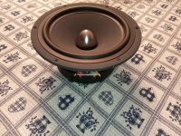
However, the choice of car speakers in my country is decent, so I decided to use 12" JBL or Hertz car subwoofers. They have a nice sensitivity and Qts, large Xmax and relatively low Mms, which I think is all important for a ripole construction.

For example, JBL Club 1224 has 275 W RMS, 93 dB, 0.58 Qts, 10.25 mm Xmax and 154.9 g Mms. It has a rated 25-175 Hz frequency range, and a ripole construction also requires a lower bass crossover, so I think I will not go above 120 Hz with it anyway.

I am also considering Hertz Dieci DS 30.3 with 250 W, 91 dB, 0.62 Qts, 9 mm Xmax, 133 g Mms, 28-300 Hz. I like that manufacturer, at least on paper, because it is the only one that I found providing the impedance graphs for their car subwoofers, so I could use that in a simulation. Unfortunately, they don't provide the frequency response graphs, so I have no idea how truthful is their claim about their rated frequency ranges.

I have read numerous threads about ripole constructions here and on other forums as techtalk and audiocircle, and I choose such type because they allegedly have:
a) the smallest enclosures (the living room where I listen music is rather small, around 5x3 m, so they will be near-field listened);

b) a good "neighbor-freendly" bass (I am living in an apartment with overly sensitive neighbors);

c) less vibrations, having push-push opposed pair of woofers, but maybe I will try first with just a single subwoofer per enclosure using the N profile (DRS-ripole).

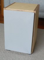
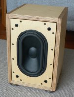
I like them also because of their aesthetics and practicality. So, I really would not like to discus about my choice of the enclosure.

Impedance mixing for OB build

I’m planning to build a Pure Audio Project inspired OB tower. Two 15” and a single fullrange. Trouble is, all the speakers I’m looking at are 8ohm. So using a pair of 15’s is going to give me either 4 or 16 ohms. The Re on one set of subs I’m considering is 5 ohms so maybe actually closer to 10 ohms for the woofers. I’ve seen many use a pair of Alpha 15a’s with TB W8-1808.

What is the work around for the mismatched impedance?

TPA6120A2 KiCad Footprint & Symbol. SMT TPA6120A2 Assembly At JLCPCB.

I am thinking of designing a PCB for $2 fab at JLCPCB for the TPA6120A2.

I was not happy with the board I bought online and thus I have been researching the various TPA6120A2 projects mentioned at DIYAUDIO and other online sources. (I have seen various TPA6120A2 projects with buffers plus a number of composites using the TLE2071 or OPA2132 or OPA1602.)

So the questions are:

1. Does anyone have a well done KiCad footprint and symbol for the TPA6120A2DWPR? (It is an extended part at JLCPCB.)

2. Has anyone ordered a SMT board with assembly including a TPA6120A2DWPR at JLCPCB? If so I would be interested in hearing any advice/experience.

I am particularly concerned about the thermal pad/e-pad/thermal vias and the SMT stencil and SMT assembly.

Nobsound G2 subwoofer amplifier issue - advice please?

Hi

I use two of these G2 amplifiers (one per channel) to drive two home-built ‘bass modules’ each with a single Dayton Audio DC-160-woofer. Long story short I put them (and the bass modules) in to my main system which consists of Tannoy R2 floorstanders, 2 x BK Gemini II sealed 10 inch subwoofers (one per channel), Arcam A28 amplifier, Arcam D33 DAC and Naim CDSi CD player. They really have helped with stage height, punch and music generally coming alive.

However, and it’s a big one, if the Arcam amplifier is switched on, when I switch the Nobsounds on at the wall (both switched off on their own switches on the amps themselves) it clicks the Arcam into protect mode. I did this once with the volume turned up and it sent a big pop through the main speakers + BK subs and I had to turn the Arcam off at the wall to get it out of protect mode. I have tried both Nobsounds individually and they both do it, yet nothing else does this on the same wall socket. The Arcam uses a different socket. Clearly I don’t want to damage the Arcam (which cost much more than the Nobsounds). I assume that the Nobsounds send something up the RCA cable and into the preouts of the Arcam when they are powered on at the wall, despite the fact that they are switched off themselves! I assume this is also happening when the Arcam is off but I just don’t know about it. I am concerned that the amps are not safe, certainly for those units upstream of them!

Is anyone else aware of this issue with this design of subwoofer amplifier? They do not seem to do it in my office system using a different main amp (AVA). Is there anything else I could try/do to stop this happening? I have just got the system pretty much exactly as I wanted it. The alternative is to replace the Nobsounds with something else that has an adjustable LPF such as 2 x BK electronics plate amplifiers or a single Dayton Audio APA 150. Unfortunately, short of cheap Chinese amps, we don’t seem to have the same choice of off-board LPF amplifiers in Europe/UK as is available in the USA - the OSD amplifiers don’t seem to be available for example.

Any advice on this would be greatly appreciated.
Regards
Alex

TTC5200 / TTA1943 amplifier sound quality

I have got one TTC5200 / TTC1943 board like one shown here
Transistor circuit diagram of 2sc5200 and 2sa1943 - Electronics Help Care

I am using a 35-0-35v transformer which gives about 47-0-47v DC. I don't think the sound is very clean like the LM3886 or LM1875 amplifiers I made before. For filtering the DC voltage I have used the same 4700uF 50v capacitor used for the LM3886 amplifier.

Is the amplifier circuit good or am I missing something here? Thanks.

recommed an amplifier for Bryston Mini-T

Hi All,

I just acquired a pair of Bryston Mini-T speakers, and am looking for a less-than $2000 amplifier, new or used, to pair with it.

The amplifier i was using for my smaller bookshelf speakers is somewhat up to the task, but has a fuzzy/weak channel, and i'd rather replace it than repair it at this point.

The preamp i plan on using is a used Parasound PLD 1100.

I look forward to any and all amplifier suggestions!

(Bryston Mini-T on the left, and my old Panasonic PMX-70 speaker on the right)

Vampyre true 75 Ohm BNC plugs

Bought these here years ago. Never used them so brand new/unused. These accept quite thick coax cable. I see I misspelled the name, it is Vampire. These were only produced for a short time and demand was low so they disappeared but they had a good reputation. Solder lugs, no crimping tool needed.

25 Euro ex shipping.

Attachments

  • IMG_2907.jpg
    IMG_2907.jpg
    60.8 KB · Views: 151
  • IMG_2908.jpg
    IMG_2908.jpg
    63.4 KB · Views: 147

Hissing DCX2496

After much fiddling around today, I found that my DCX2496 was producing hiss on one of the channels... It sounds a little like white noise.

The strange thing is, when I first turn the unit on, it's fine, and it only starts making noise after 30mins or so.

After searching around, apparently this is caused by the output PCB shorting against the case, so I opened it up, and lined the case with electrical tape.

Now, after putting it back together, I still get hiss! 😡 It's only doing it on a single channel, channel 4. Now, as I'm using 4 channels, I simply replugged the XLR into channel 6 and no more hiss...

Now, I'd like all my channels to be hiss free, how can I fix this?

Strange spots in tube.

NOS(?) tube with two white spots. Both near the getter area.

The first white spot is around a dark points on the metal construction of tube, you may see one point on the photos 1 and 2.
The dark points are close by, and big white spot on glass is the result of the merging of both areas.

The second white spot is exactly on the opposite side of the rib of tube.

What is it?
Is it ok to use tube with it?

Attachments

  • spots.jpg
    spots.jpg
    497.7 KB · Views: 147

Peerless xls Subwooferbuilds

Hello, i collect a bit Peerless xls drivers.. no Thymphany copies..

Building soon 2x "Thor" Boxes for my 830500 drivers.. they are actually new oldstock aswell.. another project i also will try is "sonosub" but with passive radiator from Scan-speak,. so 4 cabinets total.. just to try out what suits me best.. the subwoofer will be used for music, and movies.


Have also an old 1x 830452 10" with fiber dustcap and a 12 " peerless (425g) passive radiator that i will use in a passive box build im making right now..


The last one i have is a xls10 from a Gallo acoustic subwoofer.. it is playing lovely in a closed box on my stereo room at the moment.. just need to make a finish on the box.

IMG_20191208_214230.jpgIMG_20191208_214103.jpgIMG_20191205_192258.jpgIMG_20190401_212937.jpg

T.I's new 74HCS series

Through looking at logic IC's on Mouser , I found this "new" Logic Family: HCS ,
next gen HCMOS.


Maybe not audio related , but I'm sure some of us older guys still use discrete
HCMOS IC's for controling audio relays and switches.

From their site :
The HCS family is an update to the HC logic family. HCS logic modernizes
multi-gate logic functions to meet the needs and demands on today’s system
designers. Each HCS logic part, numbered SN74HCSxx, is a pin-to-pin drop-in replacement for existing HC logic parts, with no need to update designs or change development tools.
The HCS family was designed with automotive applications in mind and is the first TI logic family to launch with a complete line of both commercial- and
automotive-grade parts
.
https://e2e.ti.com/blogs_/b/analogwire/archive/2019/11/12/achieve-simpler-and-more-robust-designs

I must be missing something : "complete line of both commercial- and
automotive-grade parts"
. A whole family seems a bit much , only 25 on their site
gates , flipflops , buffers, encoders/decoders.

Quiescent current (IQ) for an HCS part is just 2 µA max, compared to 20 µA max for comparable HC logic. Each device in the 2-V to 6-V HCS family consumes 95% less power than its equivalent HC logic function, making HCS logic devices much more suitable for battery-powered designs.

They say quiescent current of just 2 uA , but that is low freq or not doing much.

https://www.ti.com/sitesearch/docs/universalsearch.tsp?searchTerm=74HCS#q=74
HCS&t=everything&linkId=1

When I look at the data sheets , lower quiescent , extended temperature like 54HC
-40 to 125C, and all Schmitt trigger inputs.
Of course 74HCS00 = 74HC132 but with lower current , ext temp
74HCS04 with ST is 74HC14 is 74HCS14
74HCS32 = 74HC7032
74HCS08 = 74HC7001 and so on.
When I compare datasheets , it seems the hysteresis is smaller than regular HC. A
few ns faster but power dissipation capitance per gate the same.
I haven't had the chance of getting my hands on them and do some testing .
Has anybody used them ?
Is the current less , near the trigger points ?

It seems like a very interesting upgrade , no HCT , but who still uses that ?
Schmitt trigger inputs are the best. And about the same price as the regular HCmos.

BMW Most25 interface amplifier

Today I found a solution and share it with you. hope it helps your job.

BMW Most 25 interface amplifier platform. Designed based on Logic 7 and this 9 channels speaker output, two channels support BMW woofer which achieved RMS Power 7X86W(4ohm),2x160W(2ohm). and could support CIC, NBT, EVO audio system, Harman, Alpine CD/DVD player, Dolby, DTS decoding system.

1. Designed according to Logic 7, some power connector, same most interface, same speaker output connector
2.9 channels speaker output, two channels support BMW woofer(2Ohm,4Ohm)
3. Support CIC, NBT, EVO audio system
4. Support Harman, Alpine CD/DVD player
5. Support Dolby, DTS decoding system
6. Install with the same cable as Logic 7
7. BMW system programming is as Logic 7
8. The same interactive interface as Logic7 (EQ, BAL, FADER, Volume system)

Attachments

  • BMW 1.png
    BMW 1.png
    47.8 KB · Views: 290
  • 1370.jpg
    1370.jpg
    929 KB · Views: 324

Velodyne DD12 : change to 220V

Hello

Could somebody give me the wiring of straps on the amplifier for a DD12 in 220v setting.
I have one in 110v setting, and I want to modify it in 220v for french voltage. I put some photos of the straps :

The Velodyne DD12 amplifier :

An externally hosted image should be here but it was not working when we last tested it.


On the components side :


An externally hosted image should be here but it was not working when we last tested it.


The straps, near the orange caps

An externally hosted image should be here but it was not working when we last tested it.


This is the 110v cabling
Who could give me the 220v cabling...

Thanks

Philippe

Crossover frequency for transmission line

Hi there
I am wanting to build a 3 way speaker with a transmission line as bass maybe from about 30 hz tuning frequency using a Morel Ultimate UW1058 (25hz to 800hz)

with a conventional sealed box for a midrange - using a Morel Supreme SCM634 ( 50Hz -7kHz)

and a tweeter ( not concerned with that yet)
My question is 2 fold
1) Where would I look to cross the bass to midrange , there is no info out there as to how wide (octaves) the bass band can be with a TL speaker

2) if I cross to the midrange at say 150 hz do I tune the midrange box to the 50 hz resonant frequency as claimed by the speaker manufacturer or do I tune the box closer to the crossover frequency I want?

thanks in advance
Clive
  • Like
Reactions: DblAA

Question about output impedance of linestage and selectable fixed attenuation

Hi all. I recently bought a Tisbury Audio passive pre to use with my Quad 306. I'm really liking it so far, but I have a quick question if anyone can help me out.

The specs on the website state that the output impedance at full volume is 0 ohms. The unit has fixed attenuations switches on the bottom to reduce the signal by a fixed -10 dB or -20 dB.

So, my question is, if I set the switches to either -10 dB or -20dB, at full volume will the output impedance still be 0 ohms? Or is the output impedance affected by the fixed attenuation?

Thanks!

Does anyone here use an AC millivolt meter?

OK,

A friend at the monthly HAM swap meet has a very clean, restored and calibrated AC millivolt meter. Dual channel 30uV to 100V. (the meter actually has two pointers). Meter has AC and dB scales.

I understand that these meters really just do one thing, probably very well, for measuring minute levels of average AC present.

What can I use this for? I was thinking along these lines:

1) Quickly evaluating power supply ripple while breadboarding and tweaking.
2) Having two channels to compare input to output.
3) Maybe some applications in negative feedback?
4) Finding crosstalk?

Is this a boat anchor, or could it be handy tweaking things? I'd have to learn it, but it seems easy.

Ultra high solder temp?

I'm trying to desolder a couple compnents on a Korean DAC and cannot seem to melt the solder! The DAC appears rather well made commercially (Calyx) and I'm using an OKI Metcal PS-900 with Smartheat. The Metcal has always been very good about delivering the right amount of heat to the soldering task but I can't get the solder joint to melt. With a lot of flux and a good size tip wetted with 60/40 I can get it to partially melt for a moment but not enough to do anything with.


Is it possible a soldering method was used in the factory that is ultra high heat that a Metcal just can't achieve? If so, what are my options? Will a computer repair shop with Hotair Rework station be able to manage? The User Manual specs don't even specify the tip temperature range on the Metcal... that I can find.

Cleaning pick up needle in year 21

Joe does people clean their PU-tips today? Ive read about using Isopropyl Alcohol (Ipa) on a brush.
Also using Magic Eraser? - I dont know what it is or how to use it.
I wonder if one could use electrolysis or ultrasound.
Could one just put a shallow tray om the platter with solution and a cotton pad for the needle to rest on, and let the vibrations or electrolysis do Its Magic? I Will try to update the post with good sugestions.
Cheers!

Magic Eraser method: Magic Eraser is also sold as Magic Sponge, Miracle Sponge, Stain removal sponge etc.
Here is a Guy showing how its done at 2 minutes 35 seconds:
How to Clean your Record Needle - YouTube

Using a stator core as a toroidal core.

I would like to ask if it is possible to use the stator iron core of a motor as the toroid core for a transformer. The original windings from a bad motor would be removed, and a single coil would be wound in such a way, as to keep the magetomotive force evenly distributed along the axis of the entire core. Such a core is segmented. In each segment a constant number would be wound. The segments would cause some magnetic flux to flow through their air gap, but that should be very small, as the permeability of air is too low. The secondary would be wound to also keep the number of turns per segment constant.

The electrical difficulty of such an arrangement is that each segment would act as an independent transformer to some extent, but this independence is slight, as the main flux passes along the entire core axis path.

If a rotor core is generously wide, one can saw off the segment sides to leave only a toroid which should behave like other mangetic toroids. The difference would be that such a core would consist of a stack of rings instead of long strip wound on itself to form a ring.

Floorstander kit

I am looking to buy a "slim" floorstander kit and i have been really interested in troel gravesen designs and was pretty shure that the Nomex 164mkii was the speaker i wanted untill he recently released the "Discovery MTM" at a little bit higher price. Now i am having issues choosing, i feel like the things that differentiate them the most are the type (TMM or MTM) because they have simular quality drivers. I will use them in a small bedroom around 10m2 so the vertical possition will vary around 1m (depending if i am laying down or sitting up). I use my speakers LOUD from time to time when watching movies 105-110db peaks.
I am still leaning towards the NOMEX 164 MKII because i like the look of a leaning speaker but if anyone have any suggestions i would be glad to have someone elses opinion on this and if they think another kit might be suitible i am open for suggestions.

Nomex: NOMEX-mkII
Discovery MTM: Discovery-MTM

Which type of huge enclosure?

I recently moved to a new house, which has an area that I get to use for a dedicated home theater. It's a larger space than the old living room, and my subwoofer, a 10" Dayton Ultimax in a sealed box, just doesn't subwoof enough anymore.

So I decided to upgrade substantially and pre-ordered a pair of Stereo Integrity HT-18 v3's. I have a QSC PLX1602 (500w x2 [or 1600w bridged] into 4 ohms) to power them (for now; might get a second amp later). Now I just need to figure out what kind of box to put them in, and with that I could use some suggestions.

Box Size Constraints:

I'm planning to build a bar (as in, the kind one sits at to drink) just behind the front row of seats, so that the bar stools function as a second row of theater seating. The top of that bar is going to be on the order of 10' long, 40" high, and 18" deep. It has occurred to me that the structure of the bar would be a great place for a subwoofer, and it could be quite a large one. If I make the lower 2/3 of the box protrude from the front (screenward) side of the bar, I have close to 50ft^3 (1400L) to work with, without really taking up any otherwise-usable space.

There is also space up front with the LCR speakers. Not enough space for a second colossal sub, but enough for a decent-size ported box. So I have the option of using one driver in the bar structure, and one in the front of the room. That's what I would prefer to do if I can come up with a design that takes advantage of the volume of the bar structure with one driver, and a smaller design that should be possible to integrate with it.

Room Dimensions:

The room measures about 20'x25', with a bathroom built out of one of the corners, so it's really about 420ft^2. It has a suspended ceiling with fiber board tiles at 8' high, and the floor is carpet on concrete. The theater area itself takes up roughly 15' square, with the TV on the 25' wall, and the 20' wall on the right.

Performance Goals:

It's a home theater subwoofer and I like bass, so of course I want it to go as low as possible and be loud. Flattish to 20hz is a requirement, and I'd like to have tangible output in the mid-teens.

I've spent some time modelling boxes in Hornresp, and I've convinced it to make some squiggly lines that seem to correlate to a tolerable frequency response, but I'm realizing that I don't know what I'm doing enough to know broadly what kind of enclosure I should be trying to design. So that's my biggest question: what kind of thing should I be trying to make?

A big, standard, vented box seems to model pretty well around 22ft^3 (600L) per driver with a 14hz tune. With 10' of length available, a transmission line makes a lot of sense to me, since I could actually fit a 14hz line with one fold and no taper. That would actually be easier to build than a vented box in this case. A tapered or mass loaded line looks a little smoother in the sim. No matter what kind of box I model, it seems to want a tune between 14 and 18 hz, and the response looks pretty good with a volume around 400L, slightly better around 600L, and excessively underdamped (I think) if it's much above that. Is there anything I could do to make better use of a larger volume?

I haven't yet put in the work to learn how to make horns work without being inconceivably large. Is something like a tapped horn worth looking into for these drivers?

fake corrugations on 15K200 Beyma

Hello to all ,

I have a pair of these loudspeakers on my system , and I am questioning about these fake corrugations . I an saying fake because the backside of the cone is totally smooth . So there is some extra thikness from place to place , on the front side of the cone .

Anyone knows the purpose of that extra thickness ?

For me , it seems useless . I'm thinking in sanding the conehttps://files.diyaudio.com/forums/images/icons/icon7.gif

Thank's in advance .

Attachments

  • 15k200 dos.jpg
    15k200 dos.jpg
    43.7 KB · Views: 456

What's the best dual I/V opamp these days???

Hey guys had great success in the past using AD844 (with no nfb), just want simple this time, got a PCM1796 dac, looking for what's the best dual I/V opamp today. Even singles at a crunch, if I get a Brown Dog converter boards.


Just looked at the old AD812 seems to have some good specs for I/V duties.
What do you guys think
145mHZ
1600 V/us slew rate
50ns settling time
-90db distortion
can't find out if it's unity gain stable or not.

Cheers George

LTSPICE KT90 directive

Hello everyone

Being unable to create myself the HT90 directive in ultra linear mode.

If anyone could post it here that would be fantastic.

I found this one but only for the pseudo triode mode 😡


* KT90 LTSpice model .subckt
KT90 P G K
Bp PKI = (0.01798272846m) * uramp (V (P, K) * ln (1.0 + (- 0.1903672493) + exp ((0.1218980633) + (0.1218980633) * ((104.4846442) + (27.71095382m) * V (G, K)) * V (G, K) / sqrt ((- 1.365059137) **
2+ (V (P, K) - (- 19.04749222)) ** 2))) / (0.1218980633)) ** (1.412945234)
.ends KT90


Thanks in advance

Class AB amp in protect when bridged

Hi guys

Amp going in protect when bridged. Both channels works flawlessly if tested in regular stereo mode, puts out full power per channel.

Does not protect in bridge mode if there is no load connected. I can see nice big sinewave on the scope.

When using 4 or 8 ohm load in bridge mode goes straight into protect. 😕

Pre-amp section seems fine with stable +-15v.

Any ideas ?

Schematic is attached.

Attachments

Apogee Buzz Fix

Hello all, OK, so I got myself a pair of Duetta Signatures the other day - always wanted a pair. Never could get my grubby hands on 'em, tho, until a few months ago. Drove four hours to pick them up. Had a whole 5 minutes to hear them. They sounded nice. Didn't really them play loud, or on anything crazy. No buzzes anywhere that I read about...so brought them home. Set them up, and took the covers off. One cover had a little crack from previous shipping damage from prior owner. Simple fix with a little sandpaper and Gorilla Glue and some gritty flat black spray paint and I was in business again. I also realigned the screen so I wouldn't see any annoying screen waves (Apogee owners kow what I am talking about). Did the other speaker and they looked 1000 times better.

The loose Tweeter/Midrange ribbon was next - it was loose and dancing around, and it concerned me a bit. The top 9" is tilted back (to give the tweets a little vertical dispersion) and runs over a piece of foam as it make the tilt back. Well foam was gone, so I went to Menards and got some Air Conditioning foam and glued a piece in and it took all the slack. No more loose Tweeter/Midrange. Yeah. All done.

So I sat and marveled at my purchase. Put on some Jennifer Warnes (Famous Blue Raincoat - man I love this cd)...It sounded great...until I raised the volume - her voice sounded like Rod Stewart. What the hell was going on? It was buzzing right on on her voice only. No where else. I was pissed. How can I miss this?

Anyway, started looking around and could really find any fix that I wanted to try, until I came across a crazy fix that was taken down from an Apogee forum I was reading. It supposedly was lost, and nowhere to be found....Finally, from some good detective work I tracked down the lost thread poster on DIYAudio (what are the chances?) A German gentleman that goes by taotao.

Ok, enough of the history, what the fix? Taotao had an idea to inject a flowable silicon into the deteriorating foam between the wooden clamps. He used some two part mixture, but one of the guys here suggested maybe a silicon that he used for windshield crack repair. I went to Autozone and purchased all they have - four tubes. Called Permatex Flowable Silicone Windshield and Glass Sealer - about $5 a tube. It actually flows ok, but needed to be thinned. Now taotao said he mixed his silicone mixture with 1/3 part silicone oil. I found some 1000ml of Silicone oil on fleabay for $5 shipped - it is from Canon (Fuser Oil S-400) and used for copiers and printers. Anyway, I put together a test batch of this mixture and noticed it flowed real well...let it dry overnight. In the morning, it was very soft, and I thought it would work perfectly.

Went to Meijer and picked up one of those kiddie medicine styringe, some 1/4 clear tubing, and a basket ball inflator needle. Pic attached. Laid teh speaker on its side and supported it so it would not tip.Sucked up some silicone goop and laid a nice bead over the front foam, right on top. The foam sucked up the silicone. I just kept laying more beads until the foam cavity was filled. Then did the other speaker, and let it dry for 6 hours. Then I turned it over and did the other front side... Didn't bother with the top or bottom foam...

That took care of the front, but what about the back? Since this mixture is a bit less viscous than honey, I let it drip down the backside foam. I stood the speaker up and injected the silicone along the back clamp corner where the foam seam is, and let it run all the way down the speaker. This took a long time as I couldn't see the silicone when it got to the bottom. Just gave it ample time (an hour). Again, the silicone drip was done through the top of the backside foam corner. I used a lot of silicone on the back clamp drips. All the excess just oozed out onto the clamp face, so no big deal. After enough drip time, I set the speaker back onto its side and allowed the silicone to drain into the foam seam. Then I did the other side and the other speaker, and let them dry a good 6 hours before trying them out. Took me all day today and a few hours last night.

Anyway, no more buzzes...A shout out to taotao - you ROCK... some pics are attached... This worked for me - and a few others - again, your mileage may vary...

Attachments

  • P1010002.JPG
    P1010002.JPG
    709.4 KB · Views: 1,545
  • P1010003.JPG
    P1010003.JPG
    678.6 KB · Views: 1,696
  • P1010006.JPG
    P1010006.JPG
    661.9 KB · Views: 1,441
  • P1010022.JPG
    P1010022.JPG
    670.4 KB · Views: 1,379
  • P1010004.JPG
    P1010004.JPG
    634.5 KB · Views: 1,398
  • P1010019.JPG
    P1010019.JPG
    709.3 KB · Views: 1,030
  • P1010018.JPG
    P1010018.JPG
    695 KB · Views: 1,466
  • P1010021.JPG
    P1010021.JPG
    624.7 KB · Views: 893
  • P1010020.JPG
    P1010020.JPG
    681 KB · Views: 901
  • P1010008.JPG
    P1010008.JPG
    715.3 KB · Views: 929

Crossover point help

Hello, I'm looking for information on how much flat frequency response (where speaker performs without colorations) I need to leave below crossover point if 24 dB/octave slopes are being used.

Rod from ESP recommends at least one octave of adequate performance below a crossover point.
Since I'm am planning to use steep 4th order 24dB/Oct slopes, could it be possible to push the crossover lower?

Cheers,
Stefan

esp 101 with a variation

Hello everyone, I present my problem for which I ask your advice.
I have built a 101 by Rod and find it a good design, especially simple and good sounding with R 8 speakers.
I am now using Yankee audio planars which measured at rest give me R2.7.
I thought I'd use the vas part of Rod's 101 to drive three pairs of Hitachi 2sk135 and 2sj50, rebuilding the pcb to accommodate the six TO3s. I have 70V on the Hitachi power amps and 58V regulated on the vas to the MJE350 mosfet driver.
I set the bias to 200ma per supply branch.
The sound of the Yankee is spectacular, never heard such beautiful, precise and impressive midrange. After listening for a long time it seemed to me that the bass was a bit behind the music scene, a bit attenuated. I have two 800VA toroidal tubes and 90,000 micro caps per channel. I tried biasing the mosfets to 300ma per branch, but the bass went back even further.
I did some measurements, on a resistive load of 8 I have at clipping 37V about 171W
on a load of 4 35V about 306W. It seems to me that by raising the bias of the mosfets they start to raise the temperature and consequently increase the rds on. This could cause the MJE350 driver to fail and no longer be sufficient to drive the six mosfets. If this is the case, I have two options. First option is to leave the mosfets at 70V, which becomes 68V at work, and increase the vas and driver to 75V regulated.
Second option is to replace the MJE350 with a more powerful one.
Do you have any suggestions or have you already gone through this experience.
Thanks to all those who want to leave a contribution.
GIUBOS

Newbie building SSE

Hello,

I am slowly gathering parts for my first build: the Tubelabs SSE. The board has many options and flexibility and I intend to use it. General outline below:

• B+ voltage of 450V (use as many different types of tubes as possible)
• 8 Ohm speakers
• Triode / UL switch
• Cathode feedback switch
• Rectifier switch
• Volume pot
• Switchable cathode bias resistors (680 Ohm, switching 680-750-910-
1K2-1K5-3K3 parallel with that)
• Considering a measurement point for tube current

Parts mainly as supplied in the parts list on the Tubelabs website, with addition of:
• C-14X choke
• Auxillary power supply cap
• Auricaps for C11 / C21
• CL1440 inrush limiter
• 2x 1N4007

For the power transformer I’m thinking of Edcor XPWR059 and output transformers Edcor CXSE25-8-5. Unfortunately, on my side of the pond (Europe, GER/NL/NOR) these things cost an arm and a leg. Any suggestions on:

• More affordable transformers
• Toroidal or “conventional” ?

And obviously, any pointers on making this plan a success are utmost welcome😀!

Cheers, Bill

Trouble setting up Amanero with I2S PCM 24Bit 384KHZ DAC

Sorry if I am spamming but i couldn't find the right thread.

I am very new to building DACs so when i saw that someone on my local market was selling a knock-off soekris DAC ( the dac accepts 4-wire I2S and is supposed to support sampling rates up to 24 bit PCM384KHZ) I thought to myself why not just give it a shot.
First off I tested it with a RPI 3b+ running Moode. I set it up to work as with Soerkis dam1021. It worked just fine so i decided to order an Amanero of audiophonics and some female to female I2S cables to set it up as a USB input.

That's where the troubles began. I am not able to get anything but the static/ white noise out of the DAC. I am pretty sure i hooked it up correctly.

GND out of amanero >> GND on dac
FSCLK out of amanero >> LRCK on dac
BCLK out of amanero >> BCK on dac
DATA out of amanero >> DATA on dac

I tried installing ASIO4all driver and still was not able to get anything out of the Amanero board.
I have seen that you are able to program the amanero but frankly speaking I am not so successful with it. And that's the main reason I am seeking help. Would appreciate if someone will be willing to share some knowledge and educate me.

Thanks in advance!

**EDIT** I forgot to add that the static / noise is only present while anything is playing on the pc. The moment the playback stops so does the static.

Carver TFM-25 Repair Questions

I’m slowly working on a Carver TFM-25 with a blown right channel, working through the schematic and trying to educate myself on the 3-rail system, and have a few questions. Repairing this amp will be mostly an educational experience, and only used for a bedroom stereo. Sonic perfection would be nice to have, but it’s not fully required.

I have built amplifiers off and on since the days of the SWTP Plastic Tiger and Tiger .01, even recently repaired a couple of Adcom 555’s, but I lack the component level skills of knowing what is a good or bad transistor substitution.

I have found one of 2SA1302’s to be open, but due to the number of counterfeits on the market, I would rather replace the PNP/NPN pair with the Hitachi 2SA1943/2SC5200 from Digikey instead. Will this work okay? Should I just get a few of each, match them, and replace them all?

My father bought this amp brand new in 1991 and it worked well until a few of years ago, when he lost the right channel. A thorough cleaning and visual inspection shows the amp in excellent shape, no brown areas on the PCB, no obvious blown or burnt components, and only a few suspect solder joints, which I touched up. The funny thing, is the left heatsink has 4-2SA1302, 1-2SA1301, 4-2SC3281, 1-2SC3280, the right heatsink has 5-2SA1302, 4-2SC3281 and 1-2SC3280. Per the schematic, the left side should be the same as the right side (the correct layout) so it looks like a factory error. From the specs, and to my untrained eye, it looks like the 2SC3281 is just a more robust version of the 2SC3280, but I’m not sure of what the sonic difference should be, or if any of the resistors should be changed for the difference in current between the 2. My question is, can I replace the 2SC1301/2SA3280 pair with the Hitachi 2SA1943/2SC5200 pair? Do I need to changes any resistors? Try to dig up matched 2SA2SC1301/2SA3280 pairs? Try a better substitution?

Last question, I usually make it a habit to change the drivers when I change any outputs, because they are cheap, and it’s cheap insurance. This amp uses 4 pairs of 2SA1370/2SC3467 as drivers and pre-drivers. Digikey doesn’t stock these, but places like B&D, Newark, MCM, etc do. I’m not sure which distributor to trust, or if I should try a possible better substitution from another reliable source.

Sorry for the long winded post, and thanks for your time!

Win

I need a pro tool version of my fingernail

one of the most useful tools I have is my fingernail but I would like something more professional.
as an example, if there are some paint spots or other gook on the front panel of a receiver I have found the best way to remove them is my fingernail

it removes them without damaging the front panel itself, metal tools will certainly remove the undesired junk, but the nice front panel is going to be scratched or gouged

I really want something easier to use
I have tried a couple wood and plastic "tools" but none of them come even close to doing the job
Is there something that people can recommend that I have not tried (which are only a few items I had lying around)

Meridian 557 rising voltage on left output

Hello lovely people, just wondering if anyone can help me, I have a meridian 557 with rising dc voltage on left output, (speaker terminals )all electrolytics have been replaced, apart from main filter capacitors. output and driver transistors test ok as do the emitter resistors, it shuts down when it reaches 5v and climbs steady from 0. Nothing seems to be getting hot. I've had a run through with the multimeter and nothing jumps out as obvious when dead testing.
I know I need to start measuring voltages now and am gonna start with the 15v regulators.
Looking to learn and hopefully fix this, any help/advice great fully received 👍

Laser adjustment on Teac VRDS-10.

Laser adjustment on Teac VRDS-10 - how?

Hi all,
I am trying to adjust the laser on the Teac VRDS-10.

So, since I am new to electronics, and I haven't done it before, I am studying the Teac VRDS-10 Service Manual.

Some of it is pretty easy to understand and I have done some tests, and a single adjustment just using my Fluke 179.

There are however some problems as I also need to connect an oscilloscope and adjust accordingly to how the waveform looks.

On the first picture one can see the test points and trimmers.

My first question:
the manual says measure an offset millivolt value of no higher than 50mV on test point 3. There is only one pin at Tp3, so I don't know how to perform that?
And I don't understand the term offset voltage?

Secondly, I also have to connect an oscilloscope plus an external tonegenerator to the player plus a single 100kOhm resistor. See picture.
While I think that the output wires from the tone generator is + and - (gnd) and the + goes to the scope and continues via the 100kOhm resistor to the test point 1, pin 1, and the - (gnd) from the tonegenerator goes from that to the scope ch1, and continue to Test point 1, pin g (gnd), I don't understand the third wire that seems to go from somewhere on the scope to the Test Point 1, pin 2. Is that the output from the cd-player on to the scope? And is that connected to what?

I am trying to learn using the scope Rigol DS1104Z Plus.

I hope you will enlighten me on the matter, so I can perform a full set of laser set up. It is MOST appreciated.

Kind regards,
SFC1000.

Attachments

  • 1.JPG
    1.JPG
    99.6 KB · Views: 149
  • 2.JPG
    2.JPG
    103.9 KB · Views: 146
  • 3.JPG
    3.JPG
    110.3 KB · Views: 130
  • 4.JPG
    4.JPG
    107.1 KB · Views: 120
  • 5.JPG
    5.JPG
    91.4 KB · Views: 129

Cambridge Audio Azur 540 fried IC chip u5

Hi, I own a Azur 540A and I was using a subwoofer with it via the Pre out. My son pulled out the Rca going from the pre to the Sub and I believe it wa sshorting out possibly. All of a sudden there was smoke coming from unit. I opened it up and noticed that u5 chip is totally fried and when turning it on the unit goes into protection mode and it sounds like the volume motor is moving. Anyone know what function that chip has and also what can i do to repair this.now. This is second Cambridge Amp to die on me. Both times from stupid mistakes.

Attachments

  • Azur540Chipu5.jpg
    Azur540Chipu5.jpg
    714.4 KB · Views: 455

Is NJM4580D an upgraded NJM4560D ?

I greet with great pleasure

I have a 1980 sony amplifier that uses NJM4560D as flat amplifier in tone section, i would like to upgrading performance like S/N, slew rate, THD. I think to use NJM4580D to replace NJM4560D

I have a question: can i use NJM4580D as direct upgrading of NJM4560D?

I only seek a direct replacement without modifying the circuit, I just want to desolder the NJM4560D chip and put in place the upgraded Op-amp.

I would greatly appreciate your comments regarding my question

Thank you.

Help with amplifier noise

:cop: Moderation edit: TLDR, start at post #10.
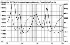
This began as a speaker thread asking to attenuate the speakers to reduce hum, and has now become an amp noise thread.
----------:cop:

So I deceided to go back to trying active again. I'm trying to connect a very powerful 6 channel amplifier I have
directly to speakers, using an active crossover and bypassing the internal crossovers. The amps are 6 - 500asp

Icepower modules. Running this much power to a tweeter
does make me a tad nervous. Also, there's some hiss and hum
I'd like to attenuate. I'd be using the 6 channel dac as a volume control.

I called Solen about whether to use an lpad or resistors and the
tech advised me to use resistors instead to pad the drivers down
using one series and one parallel resistor per driver.

So being that its a 3 way I'm thinking 9 db for the tweeter, 6db for the
mid and 3 db for the woofer. I think the tweeter is around 91db efficient,
the mid around 88 and the woofer 85 db.

My question is two fold, firstly does the resistor wattage in this case
matter that much? The thing is these amps are capable of sending
out 250 watts each, I know the drivers wont receive anywhere near
that being that I dont listen that loud and the signal will be crossed
at 450 and 2750hz. What is the minimum wattage resistor you would
use in this case?

For the parallel resistor can I just run it along the neg and pos binding
posts and then one from the pos inside the speaker?

Using this chart from Solen I've determined the following values: Solen Electronique Inc. | Values for L-Pads

tweeter - 9db attenuation: series resistor 3.9ohm parallel 3.3ohm
mid - 6db attenuation: series resistor 3.0ohm parallel 6.2ohm
woofer - 3db attenuation: series resistor 1.8ohm parallel 15ohm

I was thinking about using these 16watt mill spec resistors:
Solen Electronique Inc. | Product categories | AchrOhmiC MIL Spec Resistors

Ive attached a pic of the speaker impedance chart. Should I be ok with this?

Attachments

  • 123.jpg
    123.jpg
    33.5 KB · Views: 234

Output transformer math

OK on this little A12 amp, I am measuring a 20:1 turn ratio on the 8ohm tap and that = 3.2K primary. On the UL/screen tap I am seeing a 10:1 turn ratio on the 8ohm tap and that would be 800ohm.

Am I right in assuming then this is a 25% UL tap? Or is that a 50% tap. I get the 3.2K part but not sure how the UL/screen tap ratio part works.

I did just measure a known 3.5K into 8 ohm 40% tap SEUL transformer and got 21:1 on the primary and 8:1 on the UL so sounds like this other A12 one is a 50% tap?

This also now has me wondering, is this a PP OT they put into a SE amp? That would explain a lot.

mixing 6 stereo lines before amplifter

Hello every one , great forum with usefull info. But cant find anything of my topic , i search mixing mixer summing and other key word, but is look like forum give me the same results.
My problem is that i want to conect 6 line inputs before the amplifter (yamaha 500 ): Smart tv true some chines dac, amazon alexa , pc with additional sound Idj card , 2 microfone karaoke set, bluetooth 4,2 reciver and maybe one extra for any case.
i just fin my shop car list form local el parts website to build this:
Universal Preamp/ Mixer (Part 2) figure 1 with ne5532 op amp (only that have in shop)
with this power suply:
https://www.circuitlib.com/images/schematics/power_supply/Symmetrical_power_supply.jpg
using it this traff BV EI 303 2039 HAHN - Transformer: encapsulated | 1.9VA; 230VAC; 18V; 18V; 52mA; 52mA; 81g; BVEI3032039 | TME - Electronic components BVEI3032039
price of all that is hit 35 euro without calculating the box.
in same time i see this device:
AIYIMA 6 Ways Stereo Mixer Audio Distributor Mixing Board With Independent Volume Control DC5 24V 1PC 6 Inputs 1 Output|Amplifier| - AliExpress
without need of two line supply and still give 2 times gain on 1/3 of the price !
In fact i dosent need any amplification of the sound , i never use the yamaha amp on maximum. I just need easy and sure way to connect and switch all the inputs to the amplifter.

my question are:
1. Did i over kill the situation or is normal way to be done?
2. DIY or BUY - to continue with my DIY project or better to buy that aliexpres thing 🙂
3. How i say i dont need amplification with sure , if need something it be:
- Control the inputst true I/O pins on esp8266 maybe with paralel relays
- led indication when one line is active. (turn on if have signal) it e so usefull for troubleshooting and seting up.
4. Or to hack the yamaha amp and to put kakaoke input behind all line IN ? becouse actialy only this need to be mix, all other now is easy to switch true the buttons of the amp inputs.
:cheers:

ML332 differential output

Hi,

I am debugging my ML332 with noise issue. I have the amplifier driven by a 1KHz 50mV sinusoidal. The final output to the speaker is fine. I probed around the voltage gain board using an oscilloscope with AC coupled, and see no signal at the 1st differential stage outputs, shown by the red dots on the picture. I suspected the input impedance of 10MOhm is low, loading the output. Even I changed the probe to 100x with 100MOhm input impedance, I still cannot see any 1KHz signal at the red dot locations at the low setting of 10mV/grid, while the 1KHz tone is clearly playing at the speakers. Anyone has an idea and experience on probing the ML differential outputs? I am puzzled.


Thanks,
cfy30

Attachments

  • ML332_stage1.jpg
    ML332_stage1.jpg
    543.4 KB · Views: 87

Part identification?

I need help looking for part numbers for the plug connectors on the Precision Power, Power Class series amplifiers. I'm looking for the 2 pin, the 4 pin and the 5 pin connectors. I tired Digikey and Mouser but there so many variaties and I ran out of names types of the connectors to search any more.
Can you help?
Thanks for looking!

Attachments

  • Precision Power Plug?2.png
    Precision Power Plug?2.png
    903.7 KB · Views: 125

Pink or Brown noise generator for spectral analysis

I am requesting recommendations for a program source (a downloadable .mp4 or .wav or a Spotify album) that plays random noise that I can play thru my system, and then use a phone app spectrum analyzer to walk around and see where room resonant standing wave peaks or nulls may exist.

Yes, this is a very crude, non-calibrated method, but I am not ready to invest a lot of $$ now.

The random noise apps that I find on AppleMusic or the Android PlayStore are intended for background noise to aid mental concentration or sleep relaxation. The envelope of the spectral content varies over time to simulate ocean waves or wind or a waterfall, so that is not good for my purpose. I want noise that has a steady spectral density.

And while I am asking, what can you recommend for spectral analyzer apps? Ideally, 1/3 octave resolution or tighter, with an averaging function to smooth out those random peaks/dips in the source content.

Thanks in advance!

NAD 3020e – motorized volume control

Hi, this is Ale from Italy, any answer will be really appreciated.

I own a NAD 3020e (it's been like 12 years since I purchased it on eBay from the UK.. good old ebay times, when buy it now wasn't that commonplace), and it works perfectly. Nonetheess I miss something... a remote control, just for the volume!

I can solder and I am well experienced in DIY projects, even though not in electronics. I have found the schematics for my NAD, and it says the volume potentiometer (which is knurled) is a 50kbx2 (which I admit I don't really know what the meaning is).

Anyway, I'd like to swap it for a motorized one, with a remote control. A good start would be knowing which of the many on ebay or amazon is the right one. Then some soldering advice or how to make it work would be best.

Ciao and thanks,
Alessandro.

thoughts on a pioneer DV-79, DV-09, BDP-09 as a cd player?

hi all,

does anyone have an opinion on the following universal players as a stand alone CD player?

- DV-09
- DV-79avi
- BDP-09FD

wondering how they would stack up against my current ancient digital front end. Theta DSPro GEN III DAC, Pioneer Elite CLD-79 laserdisc player (as a transport).

the reason for all this is i've noticed my system started to sound more fatiguing. almost to the point of thinking "is there something wrong with the tweeters in my Yamaha NS-1000M?"

out of curiosity, i hooked up the CLD-79 direct to the preamp, no theta DAC (never tried this before). sounded MUCH more relaxing! who knows, maybe it's time for the theta to be recapped. not sure if i wanna go down that road.

the CLD-79 uses 1-bit DACs and legato link DSP... so that's gonna take the edge off anyway.

anywho, wondering if the above choices would wax the floor with the theta, even if it was in tip top condition.

i REALLY want a PD-93 or PD-91, but those things go for mucho dinero.

thoughts?

Regards,
Robby
Projects by fanatics, for fanatics
Get answers and advice for everyone wanting to learn the art of audio.
Join the Community
507,760
Members
7,887,261
Messages

Filter

Forum Statistics

Threads
406,173
Messages
7,887,261
Members
507,760
Latest member
The Fink