For Sale NEW APT Holman Mute Relay Adapter Boards, Assembled, Complete with Omron Relay
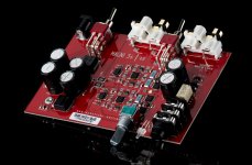
I have designed adapter boards for replacing original relays found in APT Holman preamplifiers. These relays (IDEC and Aromat) are now about 40 years old; replacements are difficult to find at best, and are not optimal for low-signal usage - they were general purpose relays. Owners of these preamps know by now that one of the most common failures in these otherwise excellent units is the relay. Relays are a maintenance item, and when they are decades old, replacement/upgrade is a good idea. We're fortunate to have really high-quality relays available in small sizes like this Omron. I've installed and tested them in my 3 APT Holman preamps, and they look and function great. Total height is much lower, since the new Omron relays are really tiny compared to the original relays. Link to Omron relay datasheet: Omron G6S
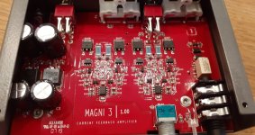
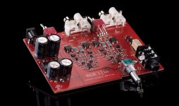
My adapter boards are extremely compact - just barely larger than the original relay footprint. They utilize a top-quality, low-signal current production relay - Omron G6S-2-Y - that has very low current draw, very low contact resistance, and very high cyclic life. They are used in expensive, high-quality audio equipment by major manufacturers, and I've used dozens and dozens of them in my multi-relay input selector boards. Their performance is excellent, even with very low MC phono signals, as well as line-level output signals.
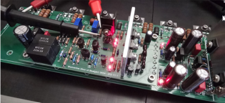
These are sold as completed and tested (on a jig with a flyback diode connected to my lab power supply) assemblies so you don't have to solder the pins or relay. The boards use header pins to connect to the original APT main preamp board. Just desolder your old relay, and pop in the new relay board assembly and resolder. I recommend you seat the pins only deep enough to solder properly so you don't have to trim the pins - there is no need to seat the adapter board against the PCB.
For the Aromat adapter board, I've revised the design to includes pads for the flyback diode closely across the power supply pads of the new Omron relay, rather than an inch or so away on the main PCB. If you want to keep your original layout, just ignore the new diode pads on the adapter board, but if you want the revised layout, let me know when you order and I'll solder in a 1N4148 for free - you will then remove the flyback diode on the Apt PCB when you replace your Aromat relay with the new board assembly.
Assemblies will be shipped by USPS in a padded envelope, with additional protection around each relay assembly. Postage costs me between $5.50 and $6.50 per envelope which costs more than $1 each, so total price is very reasonable - $34.00 for either version including shipping and PP fees (Continental US only) if using Good and Services, or $32.00 if using Friends and Family.
I've installed and tested them in my 3 APT Holman preamps, and they look and function great. Total height is much lower, since the new Omron relays are really tiny compared to the original relays.
Link to Omron relay datasheet:
Omron G6S


I've had a couple of questions about how to access the relay, and how to determine which factory relay is installed.
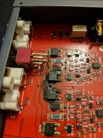
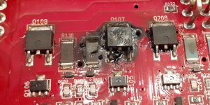
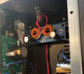
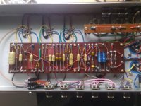
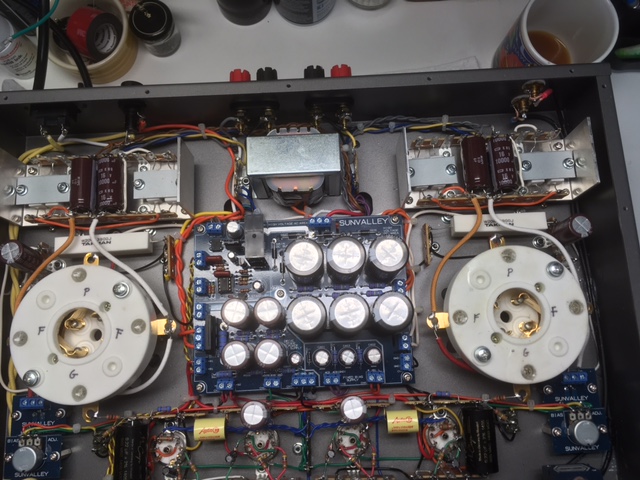
There is a bottom panel held on with Phillips head screws that are easily removed. The relay will be readily visible - you can take a photo of your relay and if you have either the Aromat or IDEC I'll let you know which one of my boards is correct.
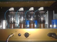
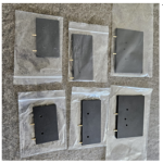
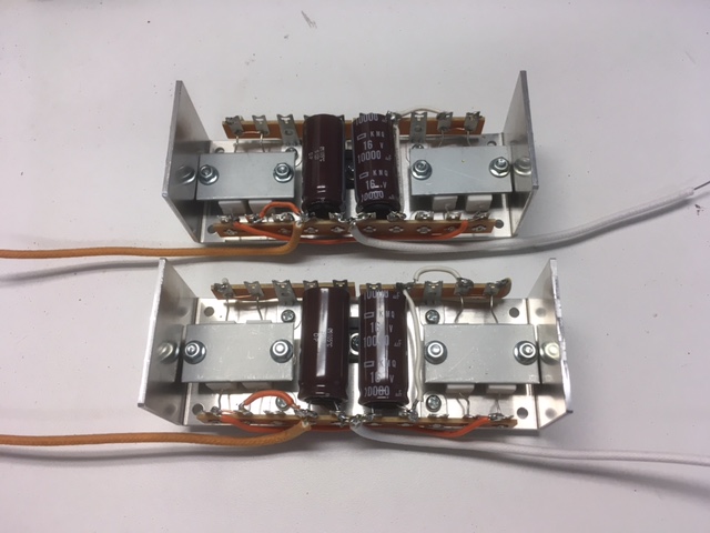
Here are the Aromat (left) and IDEC (right) original relays. Pinouts are completely different, so the adapter boards are specific. Additionally, please read the voltage markings on your relay so we are sure your unit uses a 24VDC part.

My adapter boards are extremely compact - just barely larger than the original relay footprint. They utilize a top-quality, low-signal current production relay - Omron G6S-2-Y - that has very low current draw, very low contact resistance, and very high cyclic life. They are used in expensive, high-quality audio equipment by major manufacturers, and I've used dozens and dozens of them in my multi-relay input selector boards. Their performance is excellent, even with very low MC phono signals, as well as line-level output signals.
These are sold as completed and tested (on a jig with a flyback diode connected to my lab power supply) assemblies so you don't have to solder the pins or relay. The boards use header pins to connect to the original APT main preamp board. Just desolder your old relay, and pop in the new relay board assembly and resolder. I recommend you seat the pins only deep enough to solder properly so you don't have to trim the pins - there is no need to seat the adapter board against the PCB.
For the Aromat adapter board, I've revised the design to includes pads for the flyback diode closely across the power supply pads of the new Omron relay, rather than an inch or so away on the main PCB. If you want to keep your original layout, just ignore the new diode pads on the adapter board, but if you want the revised layout, let me know when you order and I'll solder in a 1N4148 for free - you will then remove the flyback diode on the Apt PCB when you replace your Aromat relay with the new board assembly.
Assemblies will be shipped by USPS in a padded envelope, with additional protection around each relay assembly. Postage costs me between $5.50 and $6.50 per envelope which costs more than $1 each, so total price is very reasonable - $34.00 for either version including shipping and PP fees (Continental US only) if using Good and Services, or $32.00 if using Friends and Family.
I've installed and tested them in my 3 APT Holman preamps, and they look and function great. Total height is much lower, since the new Omron relays are really tiny compared to the original relays.
Link to Omron relay datasheet:
Omron G6S
I've had a couple of questions about how to access the relay, and how to determine which factory relay is installed.
There is a bottom panel held on with Phillips head screws that are easily removed. The relay will be readily visible - you can take a photo of your relay and if you have either the Aromat or IDEC I'll let you know which one of my boards is correct.
Here are the Aromat (left) and IDEC (right) original relays. Pinouts are completely different, so the adapter boards are specific. Additionally, please read the voltage markings on your relay so we are sure your unit uses a 24VDC part.