Finishing options for MDF

What easy options are there for getting a reasonable-looking finish on MDF? I have neither the skill nor the patience for anything that will take many hours to complete, and I don't have a dust-free environment in which to work.

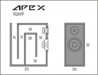
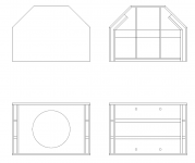
Given these constraints, I realise a showroom finish is unrealistic, but I would like my new speakers to look at least half-decent. The finished speakers will be constructed entirely from MDF, comprising four enclosures, two of 45l and two of about 10l which stack to make a pair of floorstanding speakers.

Any experience with jb JFX Premium Metallized Polypropylene Film Caps

A supplier I've used in the past (Just Radios) has these new jb JFX Premium Metallized Polypropylene Film Caps.
https://www.justradios.com/jbJFX.html

They seem pretty attractive, having good specs and a very reasonable price. The caps affordability is most likely due to the fact they are made in China.
I am looking at using them for the coupling caps in a Pass B1K.

Anyone have any experience with these caps?

https://www.justradios.com/jbJFX.html

SoundStream TA1.3000D

Just got this amp in. The owner stated that there was a "little something wrong" with it.
I first made sure that there was no continuity between B+ and GND.
I removed the cover and checked all MOSFETS on diode check and then with the ohms setting and all checked good.
I applied 13.8vdc @ 2A current limit. It maxxed that out, but I was able to see good square waves on the power supply FETS and it was building rail voltage.
I increased the current limit to 4A and it powered up with no problems pulling 2.68A with the remote on and has +/-77.2 vdc rail voltage.
I input a 50Hz sine wave @2vpp and have a good output signal.
I started increasing the gain and as I got to 160vpp, just before clipping, on the outputs I can hear a "buzz" and the peaks of the sine wave get "squiggly".
I do not have a load on the speaker terminals.
I can't pin down exactly where the buzz comes from, but it is in the area of the output filter caps and inductors.
Any clues on where and what to check next?

Rockford 250 (~2001)

Rockford 250, circa 2001, PC-3080-E. Had a blown IRF540 on right channel, blown trace & diode on the RCA shield, etc. Replaced the 540, diode, trace, and checked everything I thought necessary.

Amp works and produces clean output, but I have dc offset 10mV on the left channel and 100mV on the right. I checked and even swapped MMBT5088L Q202 and Q102 side to side with no change, and also compared them out of circuit and they seemed fine. I was looking at these because when I was checking components I get different readings from left & right when I have positive probe on the base and negative on the collector. On the left channel I get around 22k ohm and on the right I have around 6k ohm, but I haven't found anything else out of spec in close proximity to these.

How do I track down DC offset issues when it's relatively minor and still have clean output?

5/12V Bluetooth module for DIY (car radio)

Hi guys,
I have a car radio that has a jack aux input. I want to solder a 5 / 12V bluetooth module (I will definitely find these voltages on the board), but I don't know which one to choose. I had a module for $ 1-2, however the quality was average (car has good sound system), but most importantly - there was a lot of noise. What module (from aliexpress) do you recommend? Should I add a choke on + voltage? 1uH or something?

Thank you in advance and sorry for the translator

TV Analog Antenna tester?

Good Day guys, is there any know device or test equipment that can test analog tuners for a tv by sending a display test pattern based on the channel numbers, similarly how you would used a VCR on ch3 or ch4.
my problem is I can’t pick up aerial in my location when I’m servicing a TV set, and some customers need to see picture or display on the tv when it’s finished serviced. The main two channel of choice is channel 9 and channel 11. (I’m not talking about hdmi, usb, aux or composite).
melt me know if that’s available and send me the link to that particular tool.

Krell KBL Channel Imbalance

Several years back I recapped the power supply per THIS thread (which includes a partial schematic - incomplete but the best I've seen). In the past year or so I noticed a channel imbalance. On the bench I measured it at 6dB (not 100% sure cause I'm kind of a nOOb at all this). The KBL sounds fine. The imbalance is not very much so I've been compensating with the "symmetry" control (aka balance). But now I'm sick of it, so several questions.....

The first question is what to do next? My original plan was to try to chase down the signal in an attempt to find the failed components(s). But I'm not enough of an engineer to really know what I'm doing and it occured to me that the board has about 26 electrolytic caps that are all original. My inclination is to just recap the whole thing and see what happens. Would that be the best starting point? And is it possible that this just might fix things?

Second - best caps to use? The originals are all Nichicons: 470uf/100v/VX(M), 1000uf/50v/VR(M) and 100uf/10v/VX(M). Better choices?

Third - the board has 10 tiny trim pots. What to do about those after recapping? Reset somehow? But on what basis? I could try to measure some voltages on the working channel before recapping and then reset them to that after recapping? Or just leave alone if it sounds OK? Or what?

Any comments or suggestions would be greatly appreciated. I'll post results when it's all over. Thanks and cheers,

FS: B&O 200asc Stereo Amp

FS: Here are 2 Bang and Olafson 200asc modules built into a alu case. These are 200 watt amp modules with their own built in power supply. I used this for the multi amp setup powering the low freg. section of my horn speakers. Sounds great . Speakon connectors as well as binding posts. The case was repurposed so there is a hole on the front for a volume control and the back has a few extra holes as well.

The bare modules cost 149 euro in the EU.

190 euros plus shipping.

Attachments

  • IMG_7159.jpg
    IMG_7159.jpg
    516.7 KB · Views: 101
  • IMG_7160.jpg
    IMG_7160.jpg
    752 KB · Views: 108
  • IMG_7161.jpg
    IMG_7161.jpg
    526.1 KB · Views: 94
  • IMG_7162.jpg
    IMG_7162.jpg
    355.4 KB · Views: 90
  • IMG_7163.jpg
    IMG_7163.jpg
    781.1 KB · Views: 102

Aurum Cantus G1 Ribbon vs Faital Pro HF108

Hi guys
I'm working on a three way and I'm gonna use a tweeter +2.5khz over an 8" midrange. I have to candidates for tweeter but I'm in maze so I want to hear your ideas please. the overall sensitivity of speaker will be around 96db. cost is no object


option#1: Faital Pro HF108 compression driver

HF108_response_8.gif

HF108_photo_magnify.jpg


option#2: Aurum Cantus G1 Ribbon

An externally hosted image should be here but it was not working when we last tested it.

An externally hosted image should be here but it was not working when we last tested it.

FS (Europe) audax waveguided tweeters

Hello,

For sale,

A pair of Audax tw34 tweeter and monacor waveguide. Two holes were done in the flange and waveguides were cut to fit the tweeters.
Good tweeters with a lot of body in the low highs...
Asking 80€ per pair. Shipping (from France) at buyers expense.

Regards Greg.

Attachments

  • IMG_20220312_161848.jpg
    IMG_20220312_161848.jpg
    320.9 KB · Views: 126
  • IMG_20220312_161820.jpg
    IMG_20220312_161820.jpg
    345.5 KB · Views: 115
  • IMG_20220312_161619.jpg
    IMG_20220312_161619.jpg
    200.7 KB · Views: 119

Building a soundbar. Way new and have questions

Hello, I'm still doing research, but I'm wanting to start my first project by making a soundbar. I want to use the hivi b3n speakers and pre-made crossovers. I saw a thread about the b3n made as a center channel and like the way it looked. I want something similiar but as a soundbar. Apologies if these are really stupid questions.

1) I read somewhere that 3 way was good for vocals on the center channel. Is there and issue using 1 b3n for the low and 1 for the mid hookup on the crossover?

2) I read some where that 2 way is good for the left and right channels. I read about MTM design for the lh and rh speakers. Can I do this config the same way in the soundbar?

3) can I use the guts from a used soundbar to power everything or do I need to use a separate amp?

Wharfedale Diamond 11.0 modification

Redesigned to play well, even surprisingly good, for a friend from a local audio forum. The speakers were bought used, but in great condition. The original was hard to listen to, blurry sound on high, just boom boom bass without highs and details. Luckily, there was enough treble sensitivity to be able to bring it in very good condition.

The crossover was partially redesigned, the wiring was replaced with VDH CS18, all directly soldered instead of wobbly connectors. The original cables are very bad. 5cm of damping material was added to the back plate (polyester wadding). For some better quality parts, possibly a completely new crossower simply has no place in the box. And the price of that would be too high.

The sound of the redesigned boxes is very good, dynamic with a deep 3D image and a lot of details. For best results, stands and sufficient distance from the walls are required. There is no deep bass, nor can it be from a box of less than 4 liters. Bass improves a lot if they are placed against the wall, but then the depth of the sound image decreases. With some good active SUB you can get an exceptional result with little money.

Attachments

  • 11.0A.jpg
    11.0A.jpg
    58.2 KB · Views: 330
  • 11.0B.jpg
    11.0B.jpg
    45.4 KB · Views: 302
  • 11.0C.jpg
    11.0C.jpg
    80.1 KB · Views: 303
  • 11.0D.jpg
    11.0D.jpg
    46.1 KB · Views: 283
  • 11.0E.jpg
    11.0E.jpg
    55 KB · Views: 300
  • 11.0F.jpg
    11.0F.jpg
    108.8 KB · Views: 273
  • 11.0G.jpg
    11.0G.jpg
    58.6 KB · Views: 266
  • 11.0H.jpg
    11.0H.jpg
    58.8 KB · Views: 265
  • 11.0I.jpg
    11.0I.jpg
    27 KB · Views: 393

Post Recap Issues and Troubleshooting MA-5100

Hi all, I finally had time to dig into the recap of my McIntosh MA-5100. I am very new to this and am looking at this project as an opportunity to learn a lot about troubleshooting classic amplifiers so I was OK with tearing it open and replacing all of the caps (even the films, which, as I understand, rarely go bad and at best wasted my time... possibly ruined my amp).


I have also replaced some input jacks on the amp because they were smashed. Unfortunately no testing was done before moving on to the recap of the pre-amp board :headbash:

I first recapped the pre-amp board (043-989). I'm having two issues after recapping this board.

  1. The right channel only outputs a very faint signal.
    • I think I ruled out issues from the input jack replacements here because with the program source attached to the right channel only the amplifier still outputs through the left channel with the mode selector set to the following settings:
      • R TO L & R
      • STEREO REV
      • MONO (L + R)
      • L + R TO L

  2. Input signals that go through the pre-amp are practically non-existent (*extremely* faint)


Other general information:

Resistors on the output boards of both the left and right channels get extremely hot to the touch after less than a minute, regardless if a program source is playing or not. These resistors are 0.33/5W (R237/R238 for anyone with the schematic).

Mode selector switch directly follows the RCA inputs

Balance control seems to work


The Point:

Having next to zero practical experience I'm not sure where to start. I'm trying to first troubleshoot the right channel issue. Should I:

  • Visually inspect the pre-amp board solder joints?
    • I did this without a magnifying glass a few times. Could this affect sources that don't require pre-amplification? According to the block diagram these sources bypass pre-amp completely.
  • Test all transistors?
    • If not all, which would be good to test?
  • Reflow solder joints on pre-amp board?
    • Still not sure how this would affect non pre-amp inputs, but may fix the pre-amp issues.
Is there anything else I should try? Thank you all for your patience in reading through this!


--Jonathan

Technics SU-A700 mk3

Hi all,

Noobie here. I tried to establish if this is the correct sub forum is the right place to ask this question but I'm still unsure! So my apologies in advance.

I bought a Technics SU A700 mk3 amplifier along with some other separates over 20 years ago. I worked and saved really hard at the time to buy this setup. It's been really good to me. It's been sat in the same spot for the last 10 years and worked find until around 4 years ago when it just would not switch on. I was too nervous to actually open it up and see what the problem was with it being an electrical item - that shows how much I know!

So it's been sat for a length of time and I have been unable to enjoy it. The other week I tried googling why it might not work and found a video where I could see inside (wish I'd done this sooner!). So I opened it up and found a blown fuse where the power supply cable plugs in. Kicking myself thinking 'is that all that's wrong?' I googled the fuses and bought a pack of 10.

I installed the fuse and it blew straight away 😕 I tried another and the problem is consistent. So I thought I'd replace another and do some more googling and found this great place!

I've taken some pics. If anyone has experience of this error, or can point me in the right direction with simple talk of what could be wrong / what to try that would be brilliant. I would love to get it back up and running.

Many thanks

technics-1.jpg

technics-2.jpg

technics-3.jpg

Malfunctioning Onky TX-7830

Hi,

last weekend I pulled an Onkyo TX-7830 receiver (radio and amplifier in one package) by dumpster diving. My findings on it so far are the FM/RF part obviously is working, as the signal indicator shows what has to be expected at my location when I'm tuning. But there's no signal at the loudspeaker terminals, regardless the inputs. The device allows to connect two pairs of speakers, labelled FRONT and REMOTE next to the terminals at the backside. At the faceplate there's a pair of buttons to activate the speakers, labelled MAIN and REMOTE there. When I push the MAIN button, I hear the clicking of a relay and the VFD tube display shows MAIN going on and off. But nothing happens on the pushing of REMOTE. Of course I got my speakers connected to FRONT.

On searching the WWW there was a hit at Elektrotanya. I downloaded the SM as it was labelled TX-7830, TX-906, TX-904 by ET, but found that it exclusively relates to the latter two. Anyway, it is a rather complex design, mostly consisting of proprietary LSI's and µP's. The signal processing is exclusively done by IC's.

Now there are some questions: Is the TX-7830 the same as a TX-906 or 904? If so, as which of both? Does anyone have experience with the same or a similar issue with these receivers? Where should I start trobleshooting? Or do I need to bring the unit back to the dumpster (after having harvested the mains xformer and other valuable components, of course)?

Best regards!

Thoughts on 10"1" top using 10HP1020

I have a pair of faital 10hp1020 currently residing in a pair of THAM10's and I was thinking about putting them to use in a couple of small top speakers instead, togheter with say DE250 on LTH102 horns.

I have however understood that the 1020's are somewhat unique and may not "play nice" when deployed in sealed (or br) enclosures, is there anyone here with expirience or feedback/input on this? is it worth persuing or should I simply not bother?

The thinking is to use them both as "fullrange" in smaller setting or at home, and as top from ~120Hz in more demanding situations, they will be processed by driverack 260 so I can eq, delay an so on quite extensivly.

New England FrankenFest Audio GTG April 2nd 2022 West Boylston, MA

New England FrankenFest Audio GTG April 2nd 2022 West Boylston, MA

Twice a year a group of us loosely associated with AudioKarma put on an audio get together.
Our next event is Saturday April 2nd 2022.
We rent a cool old church in West Boylston MA and folks set up their gear to demo and some of it to sell.
The focus tends to be mostly on "vintage gear" from the 60's-70's-80's.
There are also folks buying an selling vinyl and a bunch of other related stuff.
Admission is a paltry $5 which is just to cover our expenses - left over money is donated to a charity and to support the AK website.
For your five bucks you get admission and also set up a table to sell if you like. There are a limited number of tables available to use.
We usually get 60-100 attendees.
For more details:
https://audiokarma.org/forums/index.php?find-new/71409048/posts

Changing crossover point on Threshold PCX 10x

I picked up this pretty little crossover but I'm a little confused about the 16 pin resistor packages. It's marked on the back as being x'ed over at 7000Hz but inside are two 8-pin resistors with the suffixes of 333 (33 KOhms) and 473 (47 KOhms). I can't figure how that adds up to 7KHz using the chart. The resistors on the other side are not labelled at all

My question is: What resistor(s) should I use to crossover at 2000Hz?

I think the chart indicates a 18.0 KOhm resistor for 1960Hz
Would this 16 pin do the trick?

https://www.digikey.com/en/products...f77ol127A7ayZrFG9HJHknW2TLyVidzwaAl0KEALw_wcB

I would also like the option of crossing over at 2,500Hz which I believe would take 14KOhm resistor package. Can I accomplish this with two 6.8KOhm 8 pin resistor arrays?

Attachments

  • 20220317_131250.jpg
    20220317_131250.jpg
    280.4 KB · Views: 179
  • 20220317_131337.jpg
    20220317_131337.jpg
    274.2 KB · Views: 203
  • 20220317_131240.jpg
    20220317_131240.jpg
    515 KB · Views: 189

Mounting the tonearm on the wrong side of the turntable

Hello there. I have a turntable without a tonearm and I have a tonearm to put on it. But the deck of the turntable is too small to mount the arm the correct distance from the spindle. I could make ugly cuts or cantilevered panels but let's just not. But suppose I mounted the deck on a heavy panel and mounted the arm across the top of the deck. The platter is close to the edge of the deck there, and I could cut a hole into the wood anywhere with a clean conscience. But that places the cable exiting the arm right next to the motor. I guess that might be a bad thing, right?

I've seen this method suggested but probably most suggestions are from people who have never done what they suggest. Has anyone done this? Have you run into hum problems from the motor?

Front Panel Designer Macro/Object Library

Folks:

Front Panel Express ceased hosting its online forum a few years ago, making collaboration with other FPD users a little more difficult. I thought it might be helpful to create a thread in which we could share FPD macros, objects and other design examples of particular note.

Here, as a first offering, is a power symbol. It isn't much, but it may save someone a bit of work.

Regards,
Scott

Attachments

  • Like
Reactions: dieter12 and Thekak

Sanyo DCA 30 bias adjust?

Hi there.
So I got that Sanyo DCA-30 which I am intending to hook to my Beovox CX-100 which I am refoaming at the moment.
I am pretty new but got interested in repairing my stuff myself and sinking deeper and deeper...
Anyway I just learned about what biasing is and the difference between Class A / AB in biasing.
My Sanyo DCA-30 works well but I have not used it a year or so and just wanted to check some thing before hoocking it up to my speakers which I put some effort in.
So I measured he DC Voltage on the speaker terminals at zero volume no speakers attached and got following result:
left channel: -240mV
right channel: -277mV
If I understand correctly this amp is working in class A so a higher bias is expected but does this look reasonable to you? and what about that 37mV difference?
I can't find any pots on the boards nor in the circuit to adjust bias.
attached the schematic. I can't find the service manual on the internet.
Any thoughts will be welcome.

Attachments

Resistor Temperature?

Novice question here. How hot are you comfortable running resistors? I am building Rod Coleman's Raw DC boards for his new V-9 regulators. I've determined that the two 0.47Ω resistors are running 105C - 110C. I've also tried two 0.22Ω in series and while cooler they still get pretty toasty. I'm using 7W WireWound Resistors that have a max temperature rating of 350C but I'm wondering if I should get a couple of the aluminum chassis mount style and bolt them to the aluminum chassis rather than have all that heat cooking the inside of the chassis and the boards?
Chassis Mount Resistors

Big Power@Great Price!

FS. I have an AS2 Ice power module in the custom Ghent audio enclosure. I put this together to run some older maggies that needed alot of power. I ran them less than 2 weeks before replacing the speakers with small bookshelf model. It is in like new condition. No that is not an exaggeration. I mean working and cosmetic condition is as new. The ghent is an excellent heavy duty all aluminum enclosure that is custom made to fit the ice modules. I'll attach data on the module and the enclosure. Anyway handsome enclosure that has no scratches or issues of any kind. I am impressed the sound of the digital amp. It is effortless on demanding loads.
So I have ~$800 in the unit now. I will take much less than that. I will accept any reasonable offer.
https://www.ghentaudio.com/kit/1200as-se.html

https://icepower.dk/buy/as-series/1200as2/

img_0698-jpg.1034469
IMG_0699.jpg
IMG_0700.jpg

Attachments

  • IMG_0698.jpg
    IMG_0698.jpg
    36.6 KB · Views: 529

Threshold 400A & CAS-1 amps, SL-10 pre & S1 power supply...?

I have been blessed by the audio gods with these!!

This stuff is insane good!!!

I recently acquired all of these items and would like to know what type of service they may need and who is qualified to work on them in the lower 48. The only issue that I have found so far is that I am only getting the right channel in the phono stage. I have not tried the tuner stage.

So far....ABSOLUTELY IMPRESSED!!!

Thanks in advance for any info!!!

Attachments

  • 20210521_191938.jpg
    20210521_191938.jpg
    469.1 KB · Views: 193
  • 20210518_010846.jpg
    20210518_010846.jpg
    348.8 KB · Views: 191

Help needed for dropping 100 volts!

Hi all,

here is a hard one for all you aficionados of electronics.


I am looking for a way to get a STABLE and Exact 100 Volts drop for a very low current application.

What i'm trying to achieve, is use a cheap 100 volt digital panel meter for measuring (monitoring) a voltage of around 140 to 170 volts area. So i will be adding 100 volts in my final measurement. For example, 152.7 volts will be displayed as 52.7.

Now i know that higher voltage meters exist, but i cannot order one right now, so i would like to proceed with what i have at hand.

I tried using a 100 volt 1.3 watt zener diode in it's reverse breakdown region, but with limited success, as far as accuracy goes, getting an error of -2 to -7 (!) volts, depending on the voltage being measured or the temperature of the zener.

The meter has an internal resistance of 75.9 ΚΩ, which i find freakingly low for a highish voltage meter, but on the other hand is enough to drive the zener current.

In case you're wondering, i'm building (i've build) a CC trickle charger/discharger for the traction battery of a hybrid car (NiMH), with a nominal voltage of 144 volts (120 cells in series), for balancing out the cells every now and then. The car only uses the battery from 40% to 80% of it's capacity, and only has balancing for every 12 cells in series (10 points),
so with time some weak cells do appear and capacity is dramaticaly decreased. The only way to bring it back is with a periodic full charge at a safe current.
Actually, 3 charge/discharge cycles gives excellent results!

So, comming back to the matter at hand, is there any other way to get a more stable and acurate 100 volt drop? Any ideas??

Thanks for any input!

FYI 830656 ND20FB-4 MTMMM from PE Board mattk

FYI
Interesting, this speaker uses four 830656 & ND20FB , simple crossover, you don't need a router.
There are no measurements.
No box specifications.

https://techtalk.parts-express.com/forum/speaker-project-gallery/38135-i-don-t-like-candles

https://techtalk.parts-express.com/...rless-mtmmm-and-mmtmmmm-2-5-way-designs/page2

post#18
mattk, "I used Zaph's ZA5.5tt crossover topology (see http://zaphaudio.com/ZA5/ ) as a starting point in PCD, since he knows what he is doing, and adjusted values to get a reasonably flat response with a good reverse null."

--
diff driver
http://zaphaudio.com/ZA5/ZA5.5t.pdf

If anyone could design a box or knows more about this speaker please post.

2SC5200+2SC1943 on 25volt Split Supply?

i was asking if 2SC5200 and 2SC1943 can handle my 25 volt split power supply
its for my amplifier i'm going to buy soon for $10 or (501 Philippine Pesos)

and i have a 20v~0~20v transformer peaked at +25v 0 -25v non regulated
the transformer has 2 secondaries (1 secondary that is center tapped)
Power supply - +25v 0 -25v 3 amperes
Amplifier - 2SC5200+2SC1943 100-150 watts @ 4 Ohms
Speaker - 2x Konzert SG-6W 150-200 watts @ 8 Ohm
i was gonna parallel the speaker for 4 Ohm Load when i bought the amplifier
i was also wondering how many watts of output at 25 volt dual power supply

Philips CD202 no sound 🥵

Hi,
Not my first player of that generation (1983). I’ve already done quite a few over the years.
But that one… 😓

Does anybody here know what the issue might be?
This is a SO-PHI model.
The reed relays are fine.
CDs are read but no sound – it worked just a week ago!
The player has just been repaired by myself. Prior to repairs, the player didn’t play anything, didn’t display anything.
I have the full service manual, checked everything on the oscilloscope and yet no sound (both channels).
Eye pattern looks absolutely perfect, if you are wondering, and all functions work.
All I can hear is a click when track changes.
Op-amps are fine.

Any leads welcome.

Thanks for looking! This picture was shot before the repairs. DIL sockets have also been replaced.

B69A8571-00D2-4A0E-A53B-0C0968B065BF.jpeg

Hip4080

I have an amplifier that makes a noise without you connecting the rca, initially the mosfet and the hip4080 were burned, then they were replaced and I am left with that noise, I do not have an oscilloscope to make measurements, I was reading in some threads that replacing the irf3710 with the irf3710z the problem is corrected. someone help me to find the error

Black Gate NX HI-Q 6.3v./ 22mfd. for sale

I have 8pcs. of the NX HI-Q 6.3v./ 22mfd. left. They're for sale on Ebay. https://www.ebay.com/itm/125037855918

I have a few other Black Gates, some New Old Stock, some were removed from circuit boards for projects that weren't completed, therefore never really "used'.
I sell on Ebay as it protects both the buyer and seller. I don't like Ebay, but it's safer and I've had a lot of overseas buyers. Ebay's Global Shipping works out best for selling outside the USA. Check out my other auctions for more Black Gate's. All are authentic Rubicon Products purchased back in 2009 from Parts Connexion. Too many to list them all here. Thanks

PE wiring with Star Ground

Hi,

I'm just seeking some clarification with the wiring of my SMPS with the protective earth and star grounding.

Question 1) I know that the earth from the IEC socket should connect to the chassis with a short wire, but should the Earth connection on my SMPS (LRS-100-36) go direct to the eic earth, or both meet at the same chassis point?

Question 2) I have 2 grounds on my PCB (pwr & aud) which come back to a star ground. Is it ok to bring them back go the chassis point with PE, or should they go to a separate point on the chassis?

Im using 17awg wiring for the 240/10A ac.

Is the attached correct or does it need a change? (ps i have covid and took about 4 hrs to write this. sorry if its a bit jumbled!)
wiring.png

Attachments

Top Cap Adhesive.

One of my 866A tubes lost it's top cap. There is some sort of friable brown spongy material under the cap. I've crimped on a piece of wire (couldn't solder to the tube pin) to the piece sticking out of the tube and will solder that wire to the cap but I'd like to use some sort of adhesive to support things. The temperature is pretty moderate at less than 50C. I was thinking some RTV adhesive but what would you folks recommend?

What's causing the "pop". Mixer input mutes.

Hi,

Im having trouble with switch pop noice when I active channels. Its a big mixer with 20 stereo inputs and 12 mono.. The schematic only shows the four first inputs on the left side but you get the idea. I wanted to leave out all the 20K resistors when they are not in use to minimize the noice from them.. (there is a lot of them with 32 inputs..) therefore I placed the switch after them. The pop noice is only present first time I activate the channel.. If I mute the channel then active it again the switch pop is gone... Same goes for all channels the pop is only there the first time I switch.

Any ideas how the make the "pop" go away?

The mixer is used with keyboards/synthesizers.

Key_Mix_1.png

Status of tube shopping (new production).

I know this thread is likely going to be locked if people don't keep it objective to the end result of the current situation (not here to talk about the situation, just the impact in tubes and likely on New Sensor, not sure if there are other relevant factories in the region), but it appears most retailers have increases retail prices in the past week AND many are sold out/backordered (with a status TBD) on top of those price increases. I know there are some factory options in other nations, but not sure of the quality, capacity, etc. NOS is not an option for many tubes (or vastly more expensive). Going to be interesting.

Tube Preamp ground lift using Bridge resistor and cap?

I`m just getting very faint ground loop. I have used chassis ground directly from the B+ Gnd. Now getting low level ground loop with 98db sensitivity speakers. Finally thinking to add a Bridge block rectifier 50A with + and - short use a 100 ohm resistor across AC inputs of the bridge and connect the AC terminal of the bridge to B+ Gnd and other to chassis earth just like how we usually do with amps. Now how far is this right when it comes to preamp. I`m using 6sn7 in Mu follower configuration.

Do I need to get the RCA -ve returns to B+ Gnd directly? instead of the on the preamp board signal ground?

Attachments

  • image_2022-03-18_002335.png
    image_2022-03-18_002335.png
    2.8 KB · Views: 598

Collecting Sony VFETs (2SJ28, 2SK82, maybe others) for curve matching and distribution on diyAudio

After all the craze about the Sony VFET parts (2SJ28, 2SK82, etc.) I had this wild idea of collecting as many of these parts as possible, run them through the curve tracer for testing and matching, and then make them available here on diyAudio. (See here why curve matching may be better than simple Vgs matching.)

I currently have 20 Sony parts which I don't need for my own amps, and there are more on the horizon. The more parts there are, the better for the matching, and the better for those in need of these parts. 🙂

My idea of making this work is as follows:
  • People sell their VFET parts to me at a reasonable price (yes, I have some money that I can borrow). Send me a personal message (PM) if you have some Sony VFETs.
  • I will also accept previously untested parts, parts that may not work properly, or parts of unknown sources (as long as I am sure I can get a refund for bad parts).
  • Once there are enough parts in the collection, people can start getting matched parts. The price will be such that it covers the average price I payed to get the parts plus a small fee that helps to keep me motivated.
  • People may also send their parts to me and get matched parts in return (for a small matching fee).
Before actually kicking this off, I'd like to get some feedback and comments on this idea. What do you guys think?

TINA spice simulation gives floating warnings

Hey guys!


I'm trying to simulate a simple mic preamp with TINA. Here's the circuit I'm using.


So I created a simulation, here it is.


When I run ERC Analysis it's all green. But when I run DC Analysis -> Table of DC Results, I get 2 warnings:

- Pin 1 of Voltage Pin Vout is floating

- Pin 2 of capacitor C3 is floating.


I tried to change that part multiple times but no luck.

Please help me out here.

Thanks!

THAT1646 vs op-amp based differential line driver

I have used the THAT1200 in projects to reject common-mode noise for balanced input. I can understand the need to use a specialized part for this purpose, as a differential receiver might require something like laser-trimmed resistors on chip to achieve high common-mode rejection.


However, there is also the THAT1646 which is a balanced output driver. Is it necessary to achieve extremely low common-mode signal on a differential output? I was thinking of a simpler solution like driving the output with a NE5532 unity positive gain and unity negative gain amplifier. The resistors would not necessarily be perfectly matched so the gain of both would not be exactly equal (probably with 1 to 2% or so I would guess), but since this difference is likely to be small and so the common-mode that is generated is likely to be small and should cause very little rejection of the audio signal at the receiver.


Or is there another reason why it is important to achieve a very balanced output that I am missing here? I would just like to avoid using a specialized part unless there is a significant benefit.

Tweeter source for mic calibration

I have ordered a couple of ND20FB-4 tweeters in order to perform second teir calibration of MEMS mics using a known microphone for the range >2kHz. The idea is that I will put the tweeter on a flat baffle placed on the floor, position the micrphones in exactly the same point in space above the tweeter and perform gated measurments in order to calibrate them. I used Vitux-cad diffraction simulator to come up with this baffle design:

1646093371933.png


I think the ripple ~5kHz will not occour as the tweeter will not be omi at this frequency. Any comments? I haven't seen anyone calibrating microphones with this kind of source before so could be making some silly mistakes.

Rockford 60 DSM

Repaired a 60dsm. It had obvious leaky caps, and overheated and ejected one of the 150ohm 2w resistors on the speaker outputs. Also replaced the LM833 opamps on the preamp riser since I had it out and had past experience of them damaged by the leaky caps. Nothing else seemed damaged in the output stage.

Amp seemingly works fine and drives above rated power, but bias pots ended up at about 10:00 and 12:00 setting them via 5mA draw. Usually they are closer to the same position. Found that one 2k bias pot read 2120ohm and the other 1842ohm. Swapped the 1842ohm for one that was about 2150ohm with no real change in the resulting position.

Should I be concerned about the difference?

Totem Hawk cabinet

Hi everybody, i have a pair of bookshelf speakers i made long time ago, based on a Troels Gravesen design. They are based on ScanSpeak 15w/8530 k01.. same woofer used in the old Totem Hawk.. I would like to try a different cabinet.. floorstander... and i was guessing if anybody knows Hawk cabinet details, volume and port dimensions, and something on stuffing.. tx in advance

First time slot loaded build, Sanity check

Hello all, I'm just looking for a quick sanity check on a proposed build.

For a little background, here were some of the constraints:

Footprint of 26.75" by 37.7" so it can support an Altec 817a cabinet. It does bring the benefit of bringing the HF horn of the system (Altec 291) near ear level and centered from the floor and wall. I could place the subs to the side but it would require moving furniture and reconfiguring the listening area.

Designed for a pair of JBL 2242h. I know its not the best "sub", if you can even call it that, but I have been building systems from public surplus parts I have acquired because they do bring good performance for the money. 100% for music listening so no need for HT level of low bass, the 817a "extend" down to 80hz according to Altec but that is more of a -6 db point, -3 db is probably 140hz. So looking for a response around 30 hz to 140 hz for the sub. I have a mini dsp and a fully active system so I have some variability on setup.

So with those constraints, I was targeting something similar to the JBL 4645C (8CF, tuned to 25 hz, +6db boost at 25hz q=2, 2nd order highpass at 25hz). Wanted to put slotted ports on the sides with a 2x4 in the middle to add bracing (so 4 ports total), and the port running the full height of the enclosure. That wasn't looking promising so I found a compromise using 3/4" MDF on the sides for 6 ports. This leaves a 9CF box with all the same parameters for the 4645C. I know the shortcomings of the design would be the 2242 will not be able to hit max power handling before running out of Xmax and setting the delay for the system will be an issue. But within Xmax gives around 114db (iirc) at 1m without boundary gain or gain from the second speaker, so more than enough output for me.

I plan on lining the cabinet with rockwool, except the back 45 degree wall that shares with the port (would the rockwool interfere with the port?). The dimensions didn't print, but the port end is 4.25" away from the back wall. Using 2x4 to brace the cabinet between the ports and 1/2" dowel rods from front to back.

I have designed sealed and ported subs with tube ports, but the is a first for a slotted port design. So, I'm just checking to see if there are any critical flaws.
sub response.png

Attachments

  • sub.png
    sub.png
    6.1 KB · Views: 109

amplificador phoenix gold octane r 15.0 1

I have an amplifier that makes a noise without you connecting the rca, initially the mosfet and the hip4080 were burned, then they were replaced and I am left with that noise, I do not have an oscilloscope to make measurements, I was reading in some threads that replacing the irf3710 with the irf3710z the problem is corrected. someone help me to find the error

Dark Days at Bose

https://www.thelayoff.com/bose

"I was with Bose for 13 years, and some of the poor decisions the company made, paved the way for where it is now.

The surround sound TV. When this was announced myself and quite a few coworkers were in shock at this decision. TV technology changes almost every year and to think that consumers would buy a 5k 42” TV, just showed the lack of market knowledge. I was standing next to my manager during this announcement and told him this was a mistake. He didn’t agree. When it was finally announced that we’re not going to make or sell them, I believe the total number sold was 5.

Building a manufacturing facility in Malaysia. This was the worst decision ever. When this was announced I told 3 of my closest buddies that in less than 5 years we would sell it. We should’ve outsourced the work to one of the many CM’s in Malaysia instead of spending millions on building a facility from scratch. And no I’m not playing Monday morning QB. More people felt the same way but were afraid to talk because it meant that the leadership didn’t know what they were doing.

And here’s another example of money being wasted. The extra +/- 100k (not sure on the exact figure anymore) given to the architect to make our logo resemble a dragon. When this was presented, everyone in the conference room looked at each other in disbelief and started laughing. Every time I and many others visited the facility, the joke was “did you see the dragon yet?”

The millions spend on this facility could have been used in R&D and market analysis."
  • Thank You
  • Like
Reactions: head_unit and GM

Question regarding phase differences of amps.

Hi all,

I was thinking about this yesterday and couldn't find any other threads that answers my question.

Given that each element in a crossover shifts the phase, as does each op amp in an amp, do different amps have different group phases when all elements are taken in to account?

Different amps will have different amount of components in them, and if the crossover is passive/after the amp this doesn't really matter.

But if you have an active system with a different amp for each band, surely that could cause big differences in the phase of each section?

Thanks, Will

perry babin i need your help! hifonics brutus bxx4000.1d blown capacitors, replaced, still in protect. guessing driver board ?

sorry everyone i tried to keep the title short and descriptive.

years ago perry babin helped me so much he is the man! would be willing to send donation like last time if we can fix board or to whomever helps me!

board: Hifonics brutus BXX4000.1d (yes the old version that is discontinued now)

Protect mode: yes

there were two blown 10uF 250v 105C capacitors, i replaced them both with same details. (the newer capacitors were slightly smaller by a few millimeters)

i could not see anymore damage anywhere else visually, i then proceeded to check the mosfets (as best i know how) with a multimeter on the ohm setting, and got .6 except for 4 fets (2 on each rail side), but they were different fets they read u30d20c and all the other mosfets that checked out at .6 read irfp064n p752d (i am guessing i am just reading or diagnosing them wrongly considering their different mosfet transistors and they are probably good?)

please let me know how i should proceed, i am assuming it is possibly some transistors on the driver board, but please assume my equipment is limited, i just have a multimeter but i am willing to buy components and replace them. my knowledge is quite limited so pictures would also help.

The green capacitor that is circled in red in the picture, i replaced both capacitors on the board like i mentioned. amp still in protect mode after replacing.

please also refer to picture of polarization to make sure i installed capacitors polarization correctly. double checking my work.

last bit of detail i can provide, the capacitors i replaced, like wow ive never seen capacitors completely blown, but the paper cardboard material in the capacitors was literally in pieces everywhere throughout the board. ive never seen a cap so violently explode before. looked like it got shot by a rifle, when i took it out there was nothing left but the rubber bottom stop and the metal connectors to it.

Attachments

  • 10uf 250v capcaitor.png
    10uf 250v capcaitor.png
    737.1 KB · Views: 517
  • polarization.png
    polarization.png
    7 KB · Views: 263
  • IMG_20220211_201939.jpg
    IMG_20220211_201939.jpg
    480.9 KB · Views: 340
  • IMG_20220211_201905.jpg
    IMG_20220211_201905.jpg
    449.6 KB · Views: 313
  • IMG_20220211_201856.jpg
    IMG_20220211_201856.jpg
    512.8 KB · Views: 337
Projects by fanatics, for fanatics
Get answers and advice for everyone wanting to learn the art of audio.
Join the Community
507,727
Members
7,886,039
Messages

Filter

Forum Statistics

Threads
406,129
Messages
7,886,039
Members
507,727
Latest member
gbartus