I have used the THAT1200 in projects to reject common-mode noise for balanced input. I can understand the need to use a specialized part for this purpose, as a differential receiver might require something like laser-trimmed resistors on chip to achieve high common-mode rejection.
However, there is also the THAT1646 which is a balanced output driver. Is it necessary to achieve extremely low common-mode signal on a differential output? I was thinking of a simpler solution like driving the output with a NE5532 unity positive gain and unity negative gain amplifier. The resistors would not necessarily be perfectly matched so the gain of both would not be exactly equal (probably with 1 to 2% or so I would guess), but since this difference is likely to be small and so the common-mode that is generated is likely to be small and should cause very little rejection of the audio signal at the receiver.
Or is there another reason why it is important to achieve a very balanced output that I am missing here? I would just like to avoid using a specialized part unless there is a significant benefit.
It depends on your application, if you have to drive 100m cable with 16 paralleled amp inputs or an unbalanced amp, or your equipment is powered from different mains phases you will need this driver.
Otherwise for home use you can make a pseudo balanced output Pin3 with only a resistor/cap to ground of same value as in the positive line.
Has the advantage of 0dB gain but the same common mode rejection.
If you want to use a driver the 1606 needs only a small cap not two 10u bipolar
Otherwise for home use you can make a pseudo balanced output Pin3 with only a resistor/cap to ground of same value as in the positive line.
Has the advantage of 0dB gain but the same common mode rejection.
If you want to use a driver the 1606 needs only a small cap not two 10u bipolar
Last edited:
Very-balanced can be nice (no radiation) but that's not the practical problem.
People connect "balanced" sources to ALL possible loads. Balanced. Partly balanced. Floating. Differential. Unbalanced one side grounded. Unbalanced other side grounded.
Source+inverter, if you ground one side, you have massive current-lumps into the short, which contaminate the power and grounds. If the source side happens to be grounded, you may have little/no signal at the ungrounded inverter output.
Transformer, screw-strip, a jumper, and brains will cover all cases. However some of the parts are expensive or scarce.
It depends on your application, if you have to drive 100m cable with 16 paralleled amp inputs or an unbalanced amp, or your equipment is powered from different mains phases you will need this driver.
Otherwise for home use you can make a pseudo balanced output Pin3 with only a resistor/cap to ground of same value as in the positive line.
Has the advantage of 0dB gain but the same common mode rejection.
If you want to use a driver the 1606 needs only a small cap not two 10u bipolar
What approach might be simple for eliminating mains hum between a preamp and an amplifier plugged into the same power strip, so they should have the same mains phase, but one that could be usable for eliminating group-loop type hum from stray fields?
As for the pseudo-balanced resistor/cap approach you suggest, would it be something the positive signal sourced by a voltage follower with say 100 ohms series resistance to pin 2, and the negative simply grounded through another 100 ohm resistor? What typical cap value to ground pin 3?
Thanks!
The 1646 is a great chip. But look carefully at the noise. An opamp based single ended to balanced output is quieter.
The 1646 is quoted at -101 dBu. A good line level hi-fin pre would have all noise and mains components below -115 dBV and spot noise figures approaching -130 dBV. The 1646 is 5 to 10x noisier than this.
I think it’s great for studio work on +4 dBu signal chains, but we can do better for hi fi.
Sorry to be blunt.
Last edited:
I was able to get much lower noise figures than -101dB when I used the 1646 as a headphone amp driver. This was not the best data that I had gotten - I think it would be closer the -125dB if I had increased the output drive to say 4Vrms. This is using Wayne Kirkwood’s class A headphone amp topology here.
Attachments
If your output has no capacitor only 100R than you put the same in the pin3 the resistor should be close to the reference gnd of the output opamp.As for the pseudo-balanced resistor/cap approach you suggest, would it be something the positive signal sourced by a voltage follower with say 100 ohms series resistance to pin 2, and the negative simply grounded through another 100 ohm resistor? What typical cap value to ground pin 3?
Thanks!
Since almost all amplifiers have Cs in the inputs you do not need the Cs even with higher offset.
welcome
@xrk971 I think your measured noise is lower because you are measuring on dBFS so ref 2 or 2.5V.
dBu will give you about 12-14 dB lower since its ref 775 mV
dBu will give you about 12-14 dB lower since its ref 775 mV
Last edited:
A line driver and a line receiver is interesting to drive a long cable or in a noisy environment (radiated external noise is canceled because signals are differential). It could be interesting to have a "XLR" interface for interfacing with others audio equipment too (classic interface of many audio equipment).
You should take a look at INA1650. I used it in a military system and it works very well. It is a little bit expensive but with great performance.
You should take a look at INA1650. I used it in a military system and it works very well. It is a little bit expensive but with great performance.
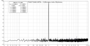
Pardon me while I revive this dead thread, but I encountered it in a search related to the THAT output drivers, which I have been working with recently, along with similar cross coupled circuits. The noise of such circuits, in both specs, simulations, and prototype measurements, has been a recent focus, so I thought I'd chime in.I was able to get much lower noise figures than -101dB when I used the 1646 as a headphone amp driver. This was not the best data that I had gotten - I think it would be closer the -125dB if I had increased the output drive to say 4Vrms. This is using Wayne Kirkwood’s class A headphone amp topology here.
You say that you were able to get much lower noise figures than -101 dBu, but that -101 dBu specification is the total noise over a 20 kHz bandwidth, and your graph shows an FFT of unknown length and sample rate, with a "lower" noise floor. I want to point out that the "-125 dBu floor" that you referenced from your graph is the noise level each of the individual frequency bands in your FFT display, and each of these individual FFT frequency band noise levels cannot be directly compared to the total summed noise of the amplifier over a 20 kHz audio band - each FFT band's "noise floor" will be far lower than the signal's total noise level.
Here's the "why". An FFT splits a signal's energy into some number of frequency bands, perhaps 16K, 64K or 256K individual bins, depending on how your equipment is adjusted. Further, the sampling rate ahead of the FFT, along with the FFT length, determines the total length of signal processed by the FFT, and also the frequency width of each bin in an FFT.
For example, using a sample rate of 44.1 kHz with a 64K point FFT will cause the machine to store and process 65536 samples of signal for each FFT, or just over a second of data. The FFT process will split this data into 32768 separate frequency bands. This means that the 22.05 kHz passband of the 44.1 kHz sampled signal will be split into 32768 bands, each having a width of around 0.673 Hz.
The FFT of a traditional signal such as a sine wave will display the same amplitude regardless of the sample rate and the length of the FFT, since a sine wave is correlated to itself over the length of the FFT acquisition interval. This means that all of the sine wave's energy ends up in the same FFT output frequency bin, and it adds coherently upon itself, since the sine wave has a stable relationship to the FFT sample frequency. So, as you are accustomed, the FFT of common test signals appears to be accurate regardless of the FFT length and sample rate settings of your analyzer.
Noise signals however are special, since they exist as a density, and not as a correlated signal. Therefore, the total amount of energy from a noise signal that ends up in each FFT frequency bin depends upon the width of each FFT bin, which depends on the sample rate and the length of the FFT. If you use a higher sample rate and/or a longer FFT, the width of each FFT frequency bin is reduced, and thus the amount of noise that gets summed into that bin will be reduced. Thus, the apparent "noise floor" level of an FFT display is greatly affected by the sample rate and FFT length settings, and without knowing those values, it's hard to assess the meaning of an FFT graph.
The moral of all of this geekery is that if you want to specify or compare noise floor levels, they have to be taken as deliberate measurements over a specific bandwidth, and that you cannot just glance at an FFT and easily extract the noise floor from the apparent noise floor of such a display. Given that there is a mathematical relationship between all of this frequency and time FFT stuff, it seems like one could apply scale factors that depend on the length of the FFT and the FFT sample rate, but all of that can still be error prone, since noise floors are rarely uniform.
At the end of the day, to get an accurate noise floor number, it's best to just band-limit the signal to a 20 kHz bandwidth and measure it directly.
Also xrk's measurement is done at an input level to the ADC of -22dB. It has negligible distortion and a THD+N measurement specified as 0.026% (basically the SINAD is all noise in this case). As a dB figure that's a SnR, whatever the weighting and bandwidth, of 71dB. Let's say we turned up the signal level by 22dB to give us a potential SnR relative to the noise floor and we get a SINAD of 93dB.
- Home
- Source & Line
- Analog Line Level
- THAT1646 vs op-amp based differential line driver