Redesigned to play well, even surprisingly good, for a friend from a local audio forum. The speakers were bought used, but in great condition. The original was hard to listen to, blurry sound on high, just boom boom bass without highs and details. Luckily, there was enough treble sensitivity to be able to bring it in very good condition.
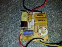
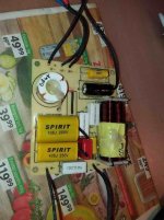
The crossover was partially redesigned, the wiring was replaced with VDH CS18, all directly soldered instead of wobbly connectors. The original cables are very bad. 5cm of damping material was added to the back plate (polyester wadding). For some better quality parts, possibly a completely new crossower simply has no place in the box. And the price of that would be too high.
The sound of the redesigned boxes is very good, dynamic with a deep 3D image and a lot of details. For best results, stands and sufficient distance from the walls are required. There is no deep bass, nor can it be from a box of less than 4 liters. Bass improves a lot if they are placed against the wall, but then the depth of the sound image decreases. With some good active SUB you can get an exceptional result with little money.
Attachments

Very nice, detailed post, my friend. Far better than most here.
Here's the Wharfedale Site:
https://www.wharfedale.co.uk/11-0/
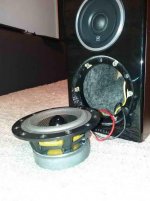
Must be 4 ohm kevlar bass in reflex and 8 ohm 1" soft dome tweeter. Looks like you have reduced treble level a sensible amount, maybe 1dB, by adding 1.2R to the filter input. These things are often too bright. And 0.22uF KEF Acoustic Butterworth style on the Tweeter, called a snubber, which tames the Fs resonance and is rather good if correctly calculated. But overall hardly enough for 6dB reduction surely?
And that 10R plus 0.33uF will hardly do anything to the bass slope. It acts at much higher frequency.
I fit Zobels like that across tweeters to just tame the top end a tiny bit.
So I am scratching my head a bit on the measurements.
Best Regards. Steve.
Here's the Wharfedale Site:
https://www.wharfedale.co.uk/11-0/
Must be 4 ohm kevlar bass in reflex and 8 ohm 1" soft dome tweeter. Looks like you have reduced treble level a sensible amount, maybe 1dB, by adding 1.2R to the filter input. These things are often too bright. And 0.22uF KEF Acoustic Butterworth style on the Tweeter, called a snubber, which tames the Fs resonance and is rather good if correctly calculated. But overall hardly enough for 6dB reduction surely?
And that 10R plus 0.33uF will hardly do anything to the bass slope. It acts at much higher frequency.
I fit Zobels like that across tweeters to just tame the top end a tiny bit.
So I am scratching my head a bit on the measurements.
Best Regards. Steve.
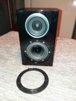
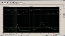
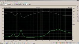
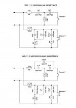
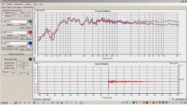
On the impedance plot it can be seen that the minimum is around 4ohm around 250Hz, so the bass driver is nominally say 5ohm. The diagram shows that I replaced the 10ohm 5W resistor in front of the tweeter with 2.2ohm 5W to raise the high range, and reduced the bipolar electrolytic 32uF to 22uF to get a linear response at medium frequencies. That's all, when I got a good measurement and checked by listening, I didn't touch anything anymore. Just better wiring and a little extra damping material on the back plate. Removing the decorative plastic ring is a living pain. It must be carefully lifted with a screwdriver little by little so as not to damage or crack the ring or driver itself. The big question is how to dismantle a plastic ring on a tweeter, if you ever need it. I haven’t even tried it.
Various values of resistors in front of the tweeter can be tested to match the rest of the system. Let's say 2.7 - 3.3 - 4.7 ohms. It is also possible to experiment with the values of the electrolytic bipolar capacitor (22 - 32uF). To play this, of course, you need some measuring equipment, such as a USB measuring microphone.
Attachments

Thank you for clarifying that, NIXIE62. I ran a sim this afternoon.
I was being a bit dim in not noticing the shunt bass capacitor was reduced from 33uF to 22uF.
That increases midrange by 2dB above 1kHz. It's impedance correction really, so the bass is a 6dB rolloff.
And misread the 3rd order tweeter input resistor as 1R in the original when it was 10R.
Going to 2.2R produces a massive 6dB increase in tweeter output.
The 0.22uF snubber network did a tiny amount of change at lower frequencies.
The 10R and 0.33uF on the bass does nothing at all, as I suspected.
The main event seems to be increasing the tweeter output and lifting the midrange a bit.
Which makes sense for more clarity. Nice work.
Regards, Steve.
Thanks. You described everything nicely, I didn't simulate anything, just rehearsing, measuring, listening. I spent three afternoons on it. As for those 10ohm + 0.33uF, I didn't know what it was for, but it certainly doesn't matter in the audible range, so I left it as it is. It can probably be taken off without any consequences.
0.22 uF is the bypass for those not very high quality polyester capacitors in the crossover. 1uF is the bypass for 22uF. I always put it on, regardless of the quality of the capacitor.
I'm sure these speakers would sound much better if new crossovers with quality parts were made, but the price of that would be similar to the price paid for used speakers.
I intentionally adjusted the speakers to be a little brighter. The owner had a budget amplifer and DAC, and these devices usually lack a bit of high spectrum and sound clarity. They sounded too harsh in my system, but it just fit into his system. If the sound is too bright, it is easy to add a higher value resistor to the tweeter without any other changes. When grills are placed, the high frequencies are slightly reduced.
That plastic ring on midbass driver should not be returned until you make sure that the sound is just right. To play with crossowers, it is best to guide the wires out of the box through the bassreflex hole. On my speakers the crossovers are out of the box, on the back panel, making it easy to adjust and not exposed to vibrations inside the box.
Last edited:
Did you borrow this modification from someone?
That 0.22uF is not a capacitor bypass. It's a KEF Acoustic Butterworth circuit. Equivalent to the familiar LCR Conjugate notch used to control the 600-1200Hz Fs resonance of tweeters.

Bit of a nightmare to calculate. I have built them. Designed to get a near perfect 18dB/octave slope.
That 0.22uF is not a capacitor bypass. It's a KEF Acoustic Butterworth circuit. Equivalent to the familiar LCR Conjugate notch used to control the 600-1200Hz Fs resonance of tweeters.
Bit of a nightmare to calculate. I have built them. Designed to get a near perfect 18dB/octave slope.
- Home
- Loudspeakers
- Multi-Way
- Wharfedale Diamond 11.0 modification