Bigbottle MM/MC Hybrid Valve Phonostage PCB
- By Bigman80
- Group Buys
- 723 Replies
Hi all,
After the release of the Bigbottle MC only phonostage (thread here: Bigbottle MC only Valve/JFET phonostage Group Buy - diyAudio) i was asked why there was no MM option by a few members. I didn't need MM so i hadn't considered it. Eventually i was approached by Andy who generously offered to redo the PCB design if we wanted to add in MM capabilities. Obviously i wasn't going to turn him down 😀
Alan redesigned the phonostage to offer MM & MC.
A few months has passed and we now have a few prototype PCB's here and rather than release them untested or as a work in progress like i did last time, we thought it would be a good idea to ask for volunteers/guinea pigs who would be willing to construct the phonostage and report back if there is any unexpected results. The idea being that when it is finalised, there will be less updates and a cleaner start to finish build process.
Obviously, you will need to have the ability to troubleshoot the PCB as it is very difficult trying to help people via phone or email. This is a lesson i learned from the first board. I'll do my best to help (I am only a "middle man" after all!) and Alan will too so you dont need to be an absolute expert but a bit of knowledge will be beneficial.
So, we have 3 PCB's available. All i ask is that it's built in the near future and that you report back any findings or measurements that need looking at.
If you are interested, please drop me a PM. Please remember, this is a not-for-profit project so all help is appreciated greatly.
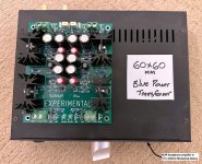
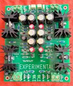
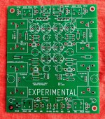
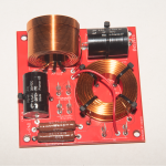
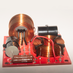
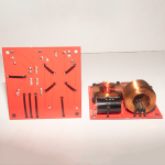
I'll add a few pics of the PCB later today.
After the release of the Bigbottle MC only phonostage (thread here: Bigbottle MC only Valve/JFET phonostage Group Buy - diyAudio) i was asked why there was no MM option by a few members. I didn't need MM so i hadn't considered it. Eventually i was approached by Andy who generously offered to redo the PCB design if we wanted to add in MM capabilities. Obviously i wasn't going to turn him down 😀
Alan redesigned the phonostage to offer MM & MC.
A few months has passed and we now have a few prototype PCB's here and rather than release them untested or as a work in progress like i did last time, we thought it would be a good idea to ask for volunteers/guinea pigs who would be willing to construct the phonostage and report back if there is any unexpected results. The idea being that when it is finalised, there will be less updates and a cleaner start to finish build process.
Obviously, you will need to have the ability to troubleshoot the PCB as it is very difficult trying to help people via phone or email. This is a lesson i learned from the first board. I'll do my best to help (I am only a "middle man" after all!) and Alan will too so you dont need to be an absolute expert but a bit of knowledge will be beneficial.
So, we have 3 PCB's available. All i ask is that it's built in the near future and that you report back any findings or measurements that need looking at.
If you are interested, please drop me a PM. Please remember, this is a not-for-profit project so all help is appreciated greatly.
I'll add a few pics of the PCB later today.


 Copyrighted materials removed by moderation.