Hello diyers,
I've been playing sub-less for few months but with time I realised I was really missing a clean first octave.
My
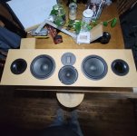
boxes are not able to go very low, it's 2x 15OB350 per side in around 200 L.
They can go low with EQ of course, but they just sound better crossed around 35/30hz, lower is just noise.
Don't know if it's the drivers high fs/qts, the "still" too small boxes or maybe not strong enough, or the room placement, probably all combined.
I see them more as big mid-bass in fact.
I had in mind to upgrade the drivers at one point, for the nero-15sw800 that should better fit the needs, but even if they're not that expensive it's still four of them that I'd need. And more important I'm not 100% convinced it will be a big improvement due to the mains placement.
So before going there I have to try spread bass again, within following constrains:
1 - nice look and integration with furnitures
2 - high sensitivity
3 - critical damping if possible
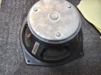
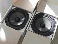
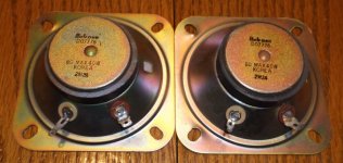
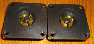
#2 means big drivers, I still have my four 18sw450 from my previous dipole, why not using them?
#2 and 3 kind of go together, but against #1 for the size implied.
#3 is a way to finally decide for myself if an L/T box can really sound the same as a big natural one (and I believe not, but lets' test).
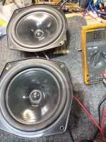
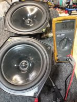
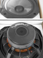
I started with what I had around and within the new room layout constrains, with a sealed um12-22 in maybe 100-120 liters (much bigger in real but with sand walls) right behind me.
Not bad at all but not enough juice, plus it's not easy to nicely integrate with the furnitures.
I couldn't try my old concrete ported one as I got rid of it few months ago (and for that I had to destroy it in place, too heavy to get out
😛). I don't regret, it stayed for years unused in the same spot, it was fun to build, but also just too bulky, and too hard to move around to test different spots.
So, I had to find a way for 2-3 subs, placed behind me, light enough to move around a bit, but big enough to not require an L/T, easy?
Thought about it few months ans was about to buy woods when… again my favorite/hated shop just launched a new serie: the
rådmansö.
Beautiful pieces in my mind, I would have loved to start with these when I've built my mains, a lot of cool stuff could be built around them.
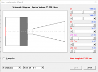
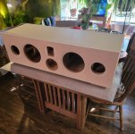
Went to see them in real, and realised even the big one could do it, this one, 159x64x46cm, 468L. :
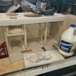
Got one, some mdf, some valchromat and let's go.
Like previous stuff I've just built a box within a box, 18mm glued all around inside, 24mm for the back, half the baffle doubled in valchromat, bracing with scraps, kind of light. The good surprise is that the radmanso is full particle boards, no honeycomb core on this like on many others, so nearly 4cm thick particles + mdf at the end.
The baffle is removable so I could add more bracing later if needed (I already found a spot that may need it).
And I could try 1 or 2 drivers, even clamshell isobaric if the box is still not big enough
😛
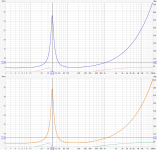
It's around 330-350 L. I'm guessing. Yes I did some sims but, they're just sims…
I of course did few mistakes again, my very first move was one! While sanding the inside of each panels for better glueing, I messed up and sanded the wrong spot of the panels, the edge that would have been visible outside. So I couldn't get the recessed baffle like I initially wanted.
Damn' what an idiot. So the baffle is now flushed, I'm sure it would have looked much better with the recess (like the mains).
Maybe I'll add a fabric grill, I'll see, it's fun to see the big driver too.
Then the valchromat was finished with tung oil, for a nice dark contrast.
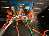
Some details are left for later like the right cable, neutrik connector, better driver screws, replace temp wheels once in place to decouple a bit etc.
Not sure I’ll use the original steel stand that comes with it, it’s sturdy but will add 20cm in height.
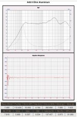
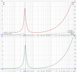
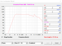
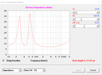
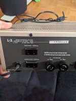
I quickly plugged one little fosi on it yesterday and it seems promising, efficient for sure.
I hope I can move it in the right place soon to measure it.
Meaning right below the diffusors behind me, where I now have a bunch of besta used for storage.
In all this I kind of try to find the same effect I had in my car years ago. I might repeat myself but it was so fun with 2x15'' at few cm right behind the head. Breathtaking was the right word, literally, and I'm not talking SPL, just air movement in your lungs even at low levels, like someone with a pump trying to empty your lungs at every beat!
Of course home environment is a total animal but if I can get 10% of this I'd be happy
😛
Will come back with measurements soon, if a success I will build another one, and maybe even 3 in total.
Cheers!


 Copyrighted materials removed by moderation.