This amazing little amp has been discussed as part of the DB thread but I think it deserves its own thread given how it has quite different objectives from the Pocket Diamond Buffer (PDB) HPA.
This desktop variant uses TO-126 output BJTs with dedicated heatsinks and does not have the separate MOSFET rail switching needed for the pocket one. The setpoints have been optimized for a moderate 40mA nominal bias current that will let you run in full Class A operation for most headphone uses. It will leave Class A around 250mW into 32 ohms. Of course, you can adjust the emitter resistors to run higher bias currents. I have used it with +/-9v, +/-12v, +/-15v and +/-18v supplies and they all work great. It was designed for 15v rails but I don’t think performance suffers much from using lower voltage. For your particular use case you may want more voltage. High impedance 300ohm cans like more voltage, for example. There is lots of room for input cap rolling and I have used huge 4.7uF 400v MKPs and also smaller 0.47uF film to bypass 10uF Elna Silmic electrolytic caps.
Here’s a photo of a built up amp board in operation:

With larger MKP caps only:

I initially struggled with an oscillation but chased it down to a feedback compensation cap that was too large. That’s all fixed now rock solid. A stability analysis on LtSpice pointed me in the right direction. So the schematic shows a 470pF cap needing to be replaced with 47pF. It’s an easy swap and I’ll do this on the SMT pre populated boards that I will be offering in my shop. I will also have bare PCBs for those wanting to assemble it themselves.
Here is schematic for the overall amp, very simple. Power supply in, audio in, audio out and volume pot with MicroMatch IDC cable to an RK09 pot helper PCB (included).

Here is schematic of the Diamond output stage:

Here is a SMT prepopulated PCB so all you need to do is to install all the through hole parts:

Both sides:

Here is the board assembled with big 4.7uF MKP caps:

Standard BOM calls for ECB pinout TO-126 BJTs (Toshiba TTA004 and TTC004) but if you have some classic Toshiba 2SA1837 and 2SC4795 (BCE pinout) you can mount them in the bottom like I did here - leaves a cleaner look on top giving you lots of access to the parts:


Testing on the bench:


Nice low distortion but second harmonic dominant distortion profile for 1Vrms into 33ohms:

You will find that this headphone amp sounds very natural and clean, but has an incredible power reserve to deliver bass slam while maintaining great control authority of the driver transducer cone. It’s a wonderful headphone amp to listen to for hours. For normal headphone use (under 500mW power) basic AC/DC modules designed for delivering circa 350mA into 15v can be used with a 7812/7913 voltage regulator and it will work fine. You can also make really fancy PSU with linear trafos, cap multipliers, CLC, and low noise LDO’s etc. with a proper PSU capable of 750mA and +/-15v you can drive up to 1.5W into 32 ohms (for those fans of the HiFiMan HE-6).
I’ll be offering the SMT preassembled PCBs for $59. Bare PCBs for $22. Boards are all 1oz copper and ENIG finish.
https://xrkaudio.etsy.com/listing/1659118057
BOM is here. Note that BOM calls for OPA1642 but the pre-populated PCB has NE5532 installed. This was due to availability issues but I can assure you that the NE5532 sounds fantastic and measures well too. If you want to swap it out later, you are welcome to do so.
If you want to boost the output BJT bias current (80mA) for operation to a higher power under Class A, use this 2.2ohm metal thin film emitter resistor (R213/213/312/313):
https://www.mouser.com/ProductDetail/Vishay-Dale/TNPW12062R20DEEA?qs=vHuUswq2%2BswIE18TmZVkaQ==
Note that the heatsinks will get significantly hotter and the PSU also needs to provide more quiescent power.
For the 8pin Wurth IDC cable with matching connector for the potentiometer, get this cable (or its equivalent).
This desktop variant uses TO-126 output BJTs with dedicated heatsinks and does not have the separate MOSFET rail switching needed for the pocket one. The setpoints have been optimized for a moderate 40mA nominal bias current that will let you run in full Class A operation for most headphone uses. It will leave Class A around 250mW into 32 ohms. Of course, you can adjust the emitter resistors to run higher bias currents. I have used it with +/-9v, +/-12v, +/-15v and +/-18v supplies and they all work great. It was designed for 15v rails but I don’t think performance suffers much from using lower voltage. For your particular use case you may want more voltage. High impedance 300ohm cans like more voltage, for example. There is lots of room for input cap rolling and I have used huge 4.7uF 400v MKPs and also smaller 0.47uF film to bypass 10uF Elna Silmic electrolytic caps.
Here’s a photo of a built up amp board in operation:
With larger MKP caps only:
I initially struggled with an oscillation but chased it down to a feedback compensation cap that was too large. That’s all fixed now rock solid. A stability analysis on LtSpice pointed me in the right direction. So the schematic shows a 470pF cap needing to be replaced with 47pF. It’s an easy swap and I’ll do this on the SMT pre populated boards that I will be offering in my shop. I will also have bare PCBs for those wanting to assemble it themselves.
Here is schematic for the overall amp, very simple. Power supply in, audio in, audio out and volume pot with MicroMatch IDC cable to an RK09 pot helper PCB (included).
Here is schematic of the Diamond output stage:
Here is a SMT prepopulated PCB so all you need to do is to install all the through hole parts:
Both sides:
Here is the board assembled with big 4.7uF MKP caps:
Standard BOM calls for ECB pinout TO-126 BJTs (Toshiba TTA004 and TTC004) but if you have some classic Toshiba 2SA1837 and 2SC4795 (BCE pinout) you can mount them in the bottom like I did here - leaves a cleaner look on top giving you lots of access to the parts:
Testing on the bench:
Nice low distortion but second harmonic dominant distortion profile for 1Vrms into 33ohms:
You will find that this headphone amp sounds very natural and clean, but has an incredible power reserve to deliver bass slam while maintaining great control authority of the driver transducer cone. It’s a wonderful headphone amp to listen to for hours. For normal headphone use (under 500mW power) basic AC/DC modules designed for delivering circa 350mA into 15v can be used with a 7812/7913 voltage regulator and it will work fine. You can also make really fancy PSU with linear trafos, cap multipliers, CLC, and low noise LDO’s etc. with a proper PSU capable of 750mA and +/-15v you can drive up to 1.5W into 32 ohms (for those fans of the HiFiMan HE-6).
I’ll be offering the SMT preassembled PCBs for $59. Bare PCBs for $22. Boards are all 1oz copper and ENIG finish.
https://xrkaudio.etsy.com/listing/1659118057
BOM is here. Note that BOM calls for OPA1642 but the pre-populated PCB has NE5532 installed. This was due to availability issues but I can assure you that the NE5532 sounds fantastic and measures well too. If you want to swap it out later, you are welcome to do so.
|
If you want to boost the output BJT bias current (80mA) for operation to a higher power under Class A, use this 2.2ohm metal thin film emitter resistor (R213/213/312/313):
https://www.mouser.com/ProductDetail/Vishay-Dale/TNPW12062R20DEEA?qs=vHuUswq2%2BswIE18TmZVkaQ==
Note that the heatsinks will get significantly hotter and the PSU also needs to provide more quiescent power.
For the 8pin Wurth IDC cable with matching connector for the potentiometer, get this cable (or its equivalent).
Last edited:

The higher orders do start appearing when you push the amp to higher power. I don’t have extensive testing on the Desktop variety yet as I did much of it with the pocket version (at +/-9v). For the pocket amp, the +/-9v rails only allowed a max of about 270mW and it left Class A at 125mW. Here is FFT of the pocket version at 270mW with third harmonic dominant but overall THD is quite low.

When pushed to clipping higher orders appear of course - this was about 370mW with the pocket Diamond Buffer HPA:

But, at typical sensible listening SPLs like 50mW, the harmonic profile is quite lovely:

When pushed to clipping higher orders appear of course - this was about 370mW with the pocket Diamond Buffer HPA:
But, at typical sensible listening SPLs like 50mW, the harmonic profile is quite lovely:
Jhofland is working on the commercial version of this amp for me. It will have built in AC/DC PSU, filter, and voltage regulators. Selectable gain with toggle switch (9/6/12dB), solid state relay mute and DC protection. All on one PCB. The Schurter IEC EMI/fuse/switch is single largest and most expensive part I think.

The prototype is coming along well. Silent during power on or off. Without music playing it is dead silence. Measurements in an AP coming soon.


I know, very basic chassis but it’s for proof of concept. The production will look much more interesting.
I know, very basic chassis but it’s for proof of concept. The production will look much more interesting.
Hello Forum Members,
Is this forum an appropriate setting for build questions, or is it meant to be mainly informational?
My specific question is: When using the large 4.7uF Audyn caps on C111 & C112, do I leave C101 & C102 unpopulated as in the pictures shown here? (Starting my build this weekend).
Thank you in advance. Dave M.
Hello Forum Members,
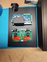
I thought I would briefly share my recent build of XRK Audio's Desktop Diamond Buffer Headphone Amp.
Because I wanted to utilize this amp sooner rather than later, I decided to go with a "ready to run" power supply. The output is 12 vdc.
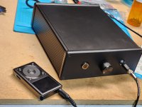
I chose a Hammond 1455U2201BK enclosure to house my project. The most time time-consuming part of assembly was the wiring, which really wasn't that bad.
I am quite pleased with the outcome. The soundstage is wide and deep, with great clarity. The bass response is great and makes for a rich sounding presentation. If anyone is considering putting one of the together I would encourage them to do it. Many thanks to XRK Audio and jhofland for an excellent sounding headamp.
I thought I would briefly share my recent build of XRK Audio's Desktop Diamond Buffer Headphone Amp.
Because I wanted to utilize this amp sooner rather than later, I decided to go with a "ready to run" power supply. The output is 12 vdc.
I chose a Hammond 1455U2201BK enclosure to house my project. The most time time-consuming part of assembly was the wiring, which really wasn't that bad.
I am quite pleased with the outcome. The soundstage is wide and deep, with great clarity. The bass response is great and makes for a rich sounding presentation. If anyone is considering putting one of the together I would encourage them to do it. Many thanks to XRK Audio and jhofland for an excellent sounding headamp.
Attachments

Oh crap, I have headphone amps in every room now, I guess I need to add another room.
Bill
Bill
I will have to try the DDB as a preamp for my FH9HVX and report back.🙂
I just wanted to hop online briefly to comment on this Desktop Diamond Buffer Headphone Amp one more time.
I used the DDB HPA as a preamp to my Honey Badger while my beloved FH9HVX is on the workbench.
X, you were right! Wow, what an amazing little preamp. I absolutely love the bass this thing puts out. Some day I want to build a low to mid-power amp/ preamp combo that would be suitable for an apartment. I think I may have found the preamp part of the equation. Thank you XRK Audio and jhofland!
Hello Forum Members,
Hypothetical question. In XRK's prototype of the DDB HPA a selector switch is available for adjusting the gain. I'm wondering what the designated gain is for diy units, and if it could be lowered without sacrificing sound quality.
I have been using this headphone amp as a preamp and, no kidding, it is my favorite of three preamps by far. The problem is I can't get past "1" on the volume knob without excessive sound level for comfortable listening. I don't completely understand the circuitry but I thought it would be worth asking. Thank you.
Hi UncleMud,
The gain is controlled by the two resistors R105/R103 for one channel and R106/R104.

Currently set at G=4k75 / 1k21 = 11.88dB
For a typical preamp perhaps circa 6dB gain is enough. Perhaps change the smaller one to circa 2k2 to 2k4 ohms.
Hope that helps.
The gain is controlled by the two resistors R105/R103 for one channel and R106/R104.
Currently set at G=4k75 / 1k21 = 11.88dB
For a typical preamp perhaps circa 6dB gain is enough. Perhaps change the smaller one to circa 2k2 to 2k4 ohms.
Hope that helps.
Hello Forum Members,
I just wanted to follow up on my previous posts regarding my desire to lower the gain on my DDB HPA. I replaced R103 and R104 with 2.4k resistor chips. I now have more latitude in adjusting the lower third of the volume control, which was my goal. This is still my favorite preamp.
As with most projects I attempt that involve SMD's the end result wasn't pretty, but it works and that is progress. With practice I am bound to improve.
Thank you X for your technical advice on this one.👍