Troubleshooting a Dynaco ST-35 noice scratching in one channel

Hi. I recently changed out all capacitors in my dynaco st-35. All was working great afterwards. Then suddenly a receive scratching clicking type noise in one channel. I take out all tubes and it is silent. I have changed the tubes out but the same problem.

I then notice after about 3-4mins smoke coming from #5 eyelet on the circuit board. Could this be too much voltage on this point.

What should i replace to solve.

Many thanks. Regards. Martin

Use Z680 Pod control in the Z5500 subwoofer, wiring provided [solved]

Hello,
I have a 
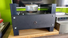
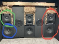
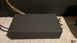
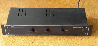
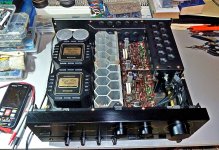
Z5500 subwoofer unit (PID R745), I managed to enable as subwoofer for my home theater following other guides.

Recently I got a 
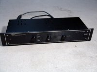
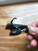
Z680 pod control for free, but sadly is not compatible with the Z5500.
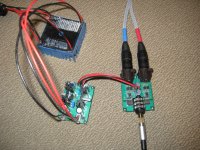
Both uses de DB15 connector (like VGA), I connected the pod to the subwoofer and the pod powers and lights but I get no sound, luckily nothing blew out.
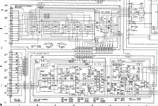
After research a wiring diagram without success I spend a few days to investigate, I managed to turn on the subwoofer and control four channels and the subwoofer (I cant get the center channel working)

image.png


Explanation of the table
The table of the left enumerates the pins in the Z680 pod (DB15 female), the third column indicates in which pin is connected in the Z5500 unit.
GND: Ground
NC: The pin is not connected to the Z680 pod
A dash is placed where the pin is not connected to the Z5500 subwoofer

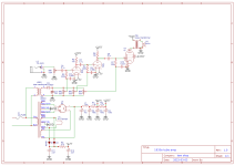
The table in the right enumerates the pins (DB15 male) in the Z5500 unit


Enable the subwoofer (PID 745)
Is important connect the pins 7 and 8 of the Z5550 to pin 13 in the same connector of the Z5500
this is enable and mute to ground. Without this the amps does nothing.
Check for your PID label outside in the bottom (is a heavy unit). Other PIDs may need another bridging or +5v supply


Weird ground in Z5500
I don't know why. But the ground in the Z5500 behaves bad with the Z680. Testing with the multi meter and the Z5500 powered off, the pin 13 is the only one connected to the general ground. But if I connect only this ground to the ground of the Z680 and the +8v. The ground sucks a lot of current. The Z680 cannot regulates the +5v of the standby and the LCD fades out. The only ground that work for my unit was the pin 11 of the Z5500. You can connect to any ground of the Z680. May be this is related to the center channel Issue.
This problem was the stop point for me in these days.
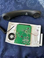

Z680 How it works
The Z680 receives +8v on the pin 10, and enter in stand-by, when the power button is pressed the LCD screen lit and the stand by pin (#7) provides +5v. May be this was the signal to power on the amps in the unit.
I suggest to test this before go for the full cabling. (pins 10 and 11)
The +18 and -18 provides the voltage to drive the audio preamp. You can connect headphones with only the +8v but the sound is weak. The +-18 volts provides the power for a proper preamp of the signal before send it to the unit.
In fact, the Z680 unit is a nice preamp as stand alone. May be you can drive a heavy headphones with this. But the +-18 is necessary.


Center Channel
In this config the center channel is not working. May be my center channel amp is blown, but I cannot get any sound from this. Or may be is related to the grounding issue. In fact i get sparks when I open the Z5500 subwoofer to fix the +18v problem.
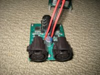
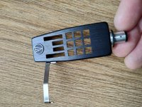
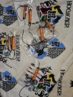

DB15
The DB15 connector is the same used in the VGA cables, you can cut and reuse a VGA cable, but I think is better use new solder connectors, these are cheap and easy to solder.
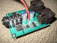
The pins are numbered viewing the male connector by the side of the pins, the wide part on the top. Top to bottom, left to rigth: This is the standard way
image.png

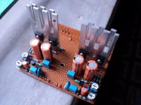
Fix +18v supply of the Z5500
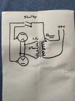
When i was testing, I connect the +18v supply to the +8v in the Z680 pod (Don't do that). This fixed my poor grounding issue and the LCD stays lit... for a few seconds (30s may be) and then, I get nothing in the +18v pin of the Z5500.
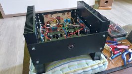
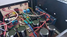
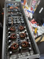
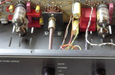
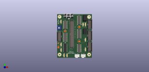
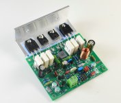
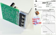
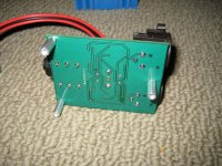
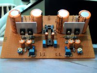
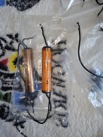
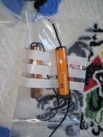
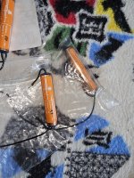
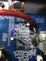
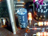
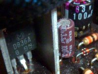
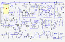
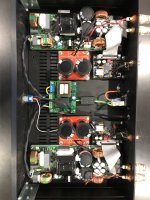
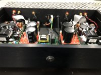
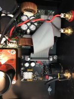
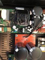
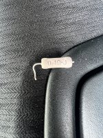
Checking the Z5500 PCB, the 78M18A regulator provides the power for the +18v. near of this is a 35.5 Ohms resistor (brown). This is the fuse for overdraw current in the regulator. I tested +31volts in one leg of the resistor and nothing in the other (was burned). I replaced the resistor with a 33 Ohms (0.25 watts rating) and the sub work fine.
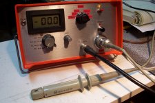
Be careful
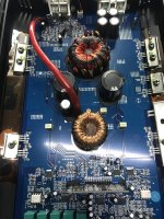
Open the Z5500 is risky, for you and the unit, take care, disconnect before check. The capacitors are big and have enough power to make a short circuit and damage the components.
Always power off the unit before plug or unplug your custom made cable to test it.
Be very careful with the multimeter points..

Thanks
I made this post after read many others. Thanks to all who managed to provide diagrams and tips.
Sorry for any typo or grammar mistake, I'm mexican, and english is not my native language.
Any suggestion or question is welcome.

F5 buzzing issue

Dear guys,
FInally, i have made F5 - took the longest time ever....
Aynway - when i connect the amp input to ground - it does not buzz...
When i leave the input of the amp open - it does not buzz....
When i connect the source to my F5 amplifier (i am using M2Tech Young dac with variable output as a dac and preamp right now) - it does buzz... i an listen to music but it buzz....
..
My amp boards are from diyAudio store
Tried to connect the 10R resistor on the amp pcb and that to my signal ground... it did nothing or very little....
will attach the some pic's and grounding schematic (sort of)....
thank You all for your time.....

edit: on the inside - two smaller boards are soft start and protection from Welleman

Attachments

  • 20230519_132143.jpg
    20230519_132143.jpg
    148.8 KB · Views: 261
  • 20230412_171257.jpg
    20230412_171257.jpg
    161.9 KB · Views: 271
  • 20230412_171302.jpg
    20230412_171302.jpg
    154.6 KB · Views: 271
  • 20230412_171307.jpg
    20230412_171307.jpg
    164.2 KB · Views: 274

Dual 866A display questions

Hi! So first things first, I understand everything about the dangers of these tubes and how to properly heat them and all that other jazz. I also have worked on guitar amplifiers for a few year. So, I’m green but not green green. With that said, I’ve always wanted to build a MV display of sorts, flip switch ohhhh ahhhh kinda thing. I have two NL866a and their filament transformer that came out of a Kepco power supply. I’d like to somehow not use a second transformer for the plates and just stick to the two tubes and the FT. I crudely made a sketch. Laugh away 😂. Am I in the ballpark? Do I need resistors on the leads going to the plates? Again, Just trying to get em to glow for a display. Thank you!

Attachments

  • IMG_7242.jpeg
    IMG_7242.jpeg
    356.6 KB · Views: 116

300b drives 300b, with interstage transformer

Hello…

Driving a 300b always seems to be a point of discussion, but I can’t seem to find a mature schematic for a 300b driving 300b - any out there?

(I also note that some designers, like Thomas Mayer have also made 211 driving 211).

Ideally I’m looking for a two stage 300b pse/pp amp with interstage transformer and an input sensitivity around 2v or thereabouts.

NAD C270 (C272) Power Amp Protection Mode - Stray Negative Voltages

Hi everyone,
I bought a non-working NAD C270 power amp a couple of weeks ago. I've made quite a bit of progress but there is still a problem somewhere (I believe) in the LEFT channel Power Amp Board. I’ve already repaired the oft-failed 68V power supply (see photo).

68V supply area problems.jpg

I wouldn't say I am at the end of my tether, but I am out of my depth understanding the fault on this one. I've read a number of forum entries here for fixing the NAD C272, which is very similar and I am using the C272 schematics because I can't find ay C270 ones. Clearly many people here on diyAudio understand schematics waaaay better than me and also some have first hand experience of these models. So any guidance or insight would be fantastic.


Current Symptoms
Amp stays in protection mode unless L channel Power Amp Board disconnected. Offset bias test points (TP2 and TP8) giving more than 56V on L channel compared to 25mV on R channel. Looking in more detail shows that the Power Amp Board comprises of a 68V end and a 64V (power transistor) end. These two ends are joined by only two connections; R328 (100 Ohm) and R356>R319+R322 (a L-FDBK call out on the schematic). All around R328 I am seeing high NEGATIVE volts compared to the right hand Power Amp Board (relative to ground).

Volts - Left PAB FAULTY_L.jpg

Volts - Right PAB WORKING_R.jpg


I can't work out exactly which end of the board (68V or 64V) these volts are coming from. Initially I suspected Q311 as it was showing -64V at the collector compared to -0.03V on Q411 (same transistor on R Power Amp Board), so I replaced Q311 and then Q310 (positive side equivalent) and then the 4 diodes (D303. D304, D305, D306). Just about every other component (save a few slightly low capacity electrolytics) seemed to test ok in circuit.


TLDR;
I've got high NEGATIVE volts running along the signal path (e.g. at the offset bias test points) on the LEFT channel only. The amplifier runs correctly with just the right channel in circuit. I can't work out how to begin finding the shorted/failed/open component on the L Power Amp Board. I've marked some schematics with my measured voltages (with CZ719 disconnected). Can anyone read my numbers into the schematic logic and suggest where I look next to find the source of these high negative volts? Main schematic attached. Any help appreciated!

Attachments

Finishing a C3M-300B

I've been off-and-on working on a C3M-300B two-chassis amplifier for a while. Everything is completed except some of the final grounding in the signal chassis. I wanted to ask the forum for advice on these last few ground connections before drilling any new holes in an otherwise finished chassis. Here's the info:

The two chassis are connected by a 10-conductor umbilical. I have 2 free signal grounds and one dedicated chassis ground running through the umbilical. The chassis ground wire also connects the umbilical copper shield at the PSU end. The L+R channels are outlined in the schematic diagram below. How would you best connect the left and right ground busses as well as speaker grounds with the available connections?

Thanks for your input. Picture are below.

evaG4L0.jpg


AKpfi4X.jpg


s9PXCEq.png

Need amplifier tester - NE FL/SE Georgia

Hi,

I have three tube amplifiers including two kits recently constructed (one of them still in progress actually). I'm looking for someone in Northeast Florida or Central Florida or Southeast Georgia who can spend a few hours one afternoon with me putting them on a 'scope for testing. I'll drive them to you. I haven't touched a 'scope in over 30 years and don't have access to one. Even if I did, I'm not qualified.

Anyone within a few hours of driving available for some testing? I'm in northeast Florida near Jacksonville.

Thanks!

Help buying or building 2-way 350hz xo

I would like to take my already made 2-way monitors and make them into a 3-way by adding another driver, ideally I would like to just add a 12Db butterworth XO at 350hz between them and hopefully without issue.

Question - Can I just design it in xsim and build it Or is there one out there I could just buy? And… how hard is xsim to learn / do ( I haven’t even downloaded it yet) if I have to? If no to both could someone just design one for me and I’ll order the parts and build it?

Details…

1. See photo - The tops are 2-way HTM12’s (green) and the bottoms are single 18” pa460’s in a 42hz box (Blue).

2. I have been running theses for two years as a 3-way (red) on a nu1000dsp amp (three amps - 6 channels - six speakers). Before eq these are an spl match so no l-pad will be needed, only some light peq will be enough.

3. These will be FULL RANGE (NOT AS A SUBWOOFER) so I WILL BE running the 18” pa’s from box tune (42hz) to 350hz and the HTM’s from 350hz and up.

4. I will be pushing a couple hundred watts to each 3-way…. Let’s say 400-600 for fun, I’m going to mono my nu1000dsp amps for each set.

5. The Htm’s and the pa460’s are 8ohms.

Attachments

  • 349831CD-1817-4D14-81B0-1BF7246422BC.jpeg
    349831CD-1817-4D14-81B0-1BF7246422BC.jpeg
    437.6 KB · Views: 79

Source(s) for large project boxes for external crossovers (

I want to move my crossovers into external enclosures, but I can't find any ABS or polycarbonate project boxes that are large enough. I've found some industrial-type enclosures, but the prices are ridiculous.
The PCBs are 16" x 10", and a few components stand about 3-1/2 inches in height. I'd like to have a little extra room so something a minimum of 18" x11", and at least 4" deep, would be ideal.

North Creek Music had some big enclosures for their B&W 801/802 crossovers, so something similar to those.

Attachments

  • 2891257-39a0a7f9-north-creek-crossovers-external-for-bampw-matrix-802-series-3-loudspeakers.jpg
    2891257-39a0a7f9-north-creek-crossovers-external-for-bampw-matrix-802-series-3-loudspeakers.jpg
    80.3 KB · Views: 104
  • SAM_1486.jpg
    SAM_1486.jpg
    134.8 KB · Views: 93

Schematic wanted for VTL Preamp "Maximal"

For this preamplifier I need schematic diagram
I don't find a download aera about
Music creates the dimension
and
Manley_Laboratories_Hi-Fi_Main_Page
perhaps one of you know, where I can ask - thank you very much.

in the attachement some pictures of this preamp:

Attachments

  • VTL_Maximal_Pre.JPG
    VTL_Maximal_Pre.JPG
    65.2 KB · Views: 1,432
  • VTL_Maximal_Pre-II inside.JPG
    VTL_Maximal_Pre-II inside.JPG
    117.4 KB · Views: 1,417
  • VTL_Maximal_Pre-II.JPG
    VTL_Maximal_Pre-II.JPG
    87.3 KB · Views: 1,415

Vintage SABA oval fullrangers?

I just bought a pair of those vintage Saba Oval Greencones Alnico. They are 17cm x 11.5cm. Apart from the classified stating that these are 5 ohms and have the 1678 CU 60 reference printed on the backs, I cannot find any kind of informations about them. I browsed some very old school german website & forums, but still couldn't find anything.

The seller said these were sold as tweeters, but are actually very competent fullrangers. They're made of paper, and the magnet looks pretty big and heavy.

Does anyone have more informations about them? I think they look really cool and would deserve a really beautiful cabinet. Although I'm pretty sure they would need some assistance in the bass region, probably...

Screenshot 2023-08-19 at 21.18.53.png

Screenshot 2023-08-19 at 21.19.07.png
Screenshot 2023-08-19 at 21.19.18.png

An electronic device that I developed to sequence power and control 4 wire fans

I'm posting this on the multiway forum because I designed this for a 3 way stand mount I made and converted to an active setup. I hope it can stay here because I think there might be some interest to others in this forum. Based on some advice I received on this forum I picked up a QSC Basis DSP on eBay and a multichannel power amp on Craigslist. The problem I needed to solve was powering on the the DSP because it has no 12V trigger input. Initially I put together a simple relay with a delay board I found on Amazon. It worked, but the delay board was a pain to program. So, since I started my career as an electronics technician I figured I can do better. At this time the Raspberry Pi 3B+ was cheap and readily available so I wire wrapped up a board to connect some relays to the GPIO bus. Little did I know at the time what was going to happen to electronic component availability and especially what happened with the Raspberry Pi. Once I had the prototype I solved the second problem I had, the micro fan in the DSP was very loud. To solve this I added an A2D chip to read the internal temperature of the DSP and replaced the fan with a 4 wire Noctua fan. Now since the fan has a tach output I added a frequency to voltage converter to read the fan speed. Finally I added more connectors to use all the unused I/O ports. All this is the usual project creep we all experience. At the same time I was learning Python to make this thing work, my programming experience had all been with assembler, C and C++ so my Python code might not look right to a Python programmer. I designed the code to be configured by editing json files or using a networked programming interface. Lastly I used NodeRed to build a web front end.

First off, I am not selling it, it is completely free to any body and I have documented it the best I can on my website. Now that Raspberry Pi are obtainable again I am releasing it to the community. I had 5 printed circuit boards made for each component, an I/O board, 5 amp relay board and 15 amp relay board. I have a few left and I will give them away. If you want a board stuffed with the electronic parts I am willing, but you would have to pay my cost for the parts. Here is a link to everything, BoMs, Gerber files, code and documentation. If you find any typos (well not if, when) let me know. If you you have any questions ask her, Pm or use the contact me on the website.

https://www.bellarossafabrica.net/av-power-manager

Attachments

  • Controller.jpg
    Controller.jpg
    403.4 KB · Views: 125
  • Controller-V3-R2.jpg
    Controller-V3-R2.jpg
    66.3 KB · Views: 118
  • Like
Reactions: kipman725

Putting out some feelers today. Would anyone be interested in trying to build a Lil' Pucker if I upload the files to Printables.

Putting out some feelers today. Would anyone be interested in trying to build a Lil' Pucker if I upload the files to Printables. Also thinking about doing a series of build vids. Just a notion, but if there is any interest I might move ahead.

Attachments

  • 20230713_171201.jpg
    20230713_171201.jpg
    263.2 KB · Views: 122
  • 20230713_170920.jpg
    20230713_170920.jpg
    294.3 KB · Views: 114
  • 20230713_170913.jpg
    20230713_170913.jpg
    329.5 KB · Views: 117
  • Screenshot_20230713_112109.jpg
    Screenshot_20230713_112109.jpg
    76.4 KB · Views: 108
  • Like
Reactions: alighiszem

About QUAD 606

In fact, I have already produced QUAD707. So there's no need to make QUAD606 again
However, due to some DIYER currently producing QUAD606 (TO3 transistor version)
I think this version is too difficult to install.
Moreover, QUAD707 has a relatively large width.
So I made QUAD606
In fact, he is almost indistinguishable from QUAD707.
Okay. It's just a difference in appearance. So I don't need to repeat the characteristics of this amplifier.
You can refer to QUAD707.
https://www.diyaudio.com/community/threads/quad-707-diy.399543/
It's just that its shape is a bit different. It is more like the installation method of L20 amplifier.
I think it can replace QUAD405. It is indeed more effective than QUAD405.
There are many circuit introductions available online on QUAD606. Interested parties can simply go to Baidu.

Attachments

  • QUAD606-1.JPG
    QUAD606-1.JPG
    352.7 KB · Views: 248
  • QUAD606-2.JPG
    QUAD606-2.JPG
    330 KB · Views: 241
  • QUAD606-3.JPG
    QUAD606-3.JPG
    241.5 KB · Views: 197
  • QUAD606-4.JPG
    QUAD606-4.JPG
    430.1 KB · Views: 220
  • QUAD606-5.JPG
    QUAD606-5.JPG
    172.4 KB · Views: 208
  • QUAD606-6.JPG
    QUAD606-6.JPG
    274.7 KB · Views: 204
  • QUAD606-散件.JPG
    QUAD606-散件.JPG
    641.5 KB · Views: 222

crossover circuit : 2nd or 3rd order?

Hi everyone, I'm a new member, honored to be part of this community of fans.
(I'm Italian, sorry but I use google translate)
I have a technical question to ask you: I have a Berhinger equalizer and I can not understand the operation of its high-pass filter shown in the figure (the section in the blue box), or rather it is not clear to me how to identify the model that determines the order of the filter. From the bottom of my ignorance it seemed to me a 2nd order and calculating the min and max cutting frequencies you get values equal to about 10Hz and 250Hz. On the potentiometer instead 10Hz and 400Hz are indicated and in the description of the command we read: "The LOW CUT regulator establishes the lower frequency of the limit of the ULTRAGRAPH PRO. The high-pass filter (18 dB/oct) is adjustable in a range of 10 to 400 Hz. If this filter is in the 10 Hz position, let the signal pass through without affecting it in the slightest."
Can you help me understand the pattern and determine the formula to calculate the cutoff frequency? Does the 100 Ohm resistor (R176) have anything to do with it?
Thank you very much if you can clarify this point for me.
(the goal is to replace the potentiometer with a switch and resistors to have preset frequencies)

SCHEMA FILTRI.jpeg

"The Wire" Ultra-High Performance Headphone Amplifier - PCB's

A new run of these boards is now available! Please see the following thread for details:

http://www.diyaudio.com/forums/soli...ble-here-bal-bal-se-se-lpuhp.html#post3516741

There is a Wiki here which contains all the project information, documentation and details for all "The Wire" projects:

The Wire - All Boards and Kits Explained Here!

Hi Guys,

I just finished building my latest headphone amplifier project, and this one is definitely worth sharing with the community. After a few prototypes, I went ahead and had some PCB's made, and there are plenty extra available if people are interested.

I basically wanted a headphone amplifier that was as close as could be to a wire with current gain. I didn't want it to impart anything at all to the source signal. That led me to the following design criteria:

- Perfectly flat FR from DC to over 100kHz
- No phase shift from 0-100kHz
- No capacitors (except for PSU)
- Extremely low harmonic distortion
- Extremely low IM distortion
- Extremely low noise floor
- Ability to drive down to 4 ohms with no load dependence
- Enough voltage swing to drive any reasonable headphone set.
- Excellent input CMRR
- Simple circuitry using the best parts available.

I needed a balanced input, and wanted to use a standard 1/4" jack for the output.

The resulting amplifier is basically an instrumentation amp using three LME49990 op-amps and an LME 49600 buffer nested into the last stage. These parts represent the absolute best you can get for this sort of application. I used all 0.1% Susumu thin film resistors, and all X7R ceramic bypass capacitors placed directly on the supply pins. Bulk caps are all solid polymer for the absolute lowest ESR and best HF performance. Layout was optimized for short signal length, low noise and low crosstalk.

The circuit provides differential input, or the option to ground one phase and drive the circuit with an SE input. Gain is set to 1, but can easily be changed to pretty much anything with just two resistors It runs on +/-5VDC up to +/- 15VDC and has enough drive to run anything you can throw at it.

As for sound, having a DC coupled amplifier makes for some of the most stunning bass I have ever heard. I'm driving a pair of Denon AH-D2000 headphones, and there's a world of difference between this amplifier and every other source I have ever tried when it comes to performance below 100Hz. It has incredible impact, depth and cleanliness. In the midrange and top end, it passes on the characteristics of the source like nothing I have ever heard. I've driven it with an Aikido linestage, a BZLS, straight from a DAC and a multitude of other devices, and all you hear is the device driving it. I now use this setup as my primary means of evaluating all preamps and sources since nothing else I have ever used even comes close to exposing the true nature of the sources like this circuit does. It's honestly like it's not even there... hence the name.

I've attached some pictures of the finished product below, and I'll follow up with some measurements done on an Audio Precision. Schematic to follow also.

Cheers,
Owen

Attachments

  • Whole amp connected.jpg
    Whole amp connected.jpg
    319.5 KB · Views: 42,549
  • Whole Amp Disconnected.jpg
    Whole Amp Disconnected.jpg
    453.6 KB · Views: 39,205
  • Amp and PSU.jpg
    Amp and PSU.jpg
    426.6 KB · Views: 37,598
  • Amp Side.jpg
    Amp Side.jpg
    406.5 KB · Views: 36,909
  • Close-up.jpg
    Close-up.jpg
    250.8 KB · Views: 36,441
  • Amp Bottom.jpg
    Amp Bottom.jpg
    354.5 KB · Views: 10,387
  • Amp Front.jpg
    Amp Front.jpg
    359.6 KB · Views: 8,502

Goldring 1012 GX Cartridge Head Shell Compatibility

Hi - I am planning on changing the head shell on my Audio-Technica AT-1005 Mk2 tonearm and am wondering about how I will re-mount my 1012 GX cartridge as the two head shells are quire different. My existing head shell is an Audio-Technica MG9 which has the mounting screws screwed from below the cartridge into the body of the head shell, whereas the replacement head shell, an Audio-Technica S8 is of a more skeletal design that looks as though it would need nuts to secure the two bolts. Perhaps I just need to purchase the nuts? Are they all a standard size? I'll attach a couple of photos of my existing arrangement and one of the new head shell that I have ordered. Thanks.

Attachments

  • IMG_4835.jpg
    IMG_4835.jpg
    252.5 KB · Views: 76
  • IMG_4836.jpg
    IMG_4836.jpg
    272.9 KB · Views: 88
  • s-l1600-2.jpg
    s-l1600-2.jpg
    386.5 KB · Views: 73

Best capacitors for power supplies update

Electrolytic capacitors types for power supplies come and go. They attend different demands than stages interface or other more subtle applications.

Some are large and recommended for main raw filtering, usually before regulators. Some are small and have to take care of smaller currents.

Raw supply filtering usually requires low-esr and high temperature, even if large cans rarely fulfill any of those. That's why some people use smaller caps wired in parallel. Caps after regulators usually DON'T have to be low-esr.

The question is which brand types have worked for you in both places.

High Efficiency Open Baffle w/ 10" Woofer

Greetings all,

I’m planning my next system to correspond with a new apartment. It’s a 700sq/feet with lofted cielings. The walls are very thin so I can’t bring my previous system with me. I’m trying not to disturb the neighbors. The follow are my thoughts on a system using parts on hand, but I'm open to suggestions about what would work best with the space

I already have two full range audio nirvana super 8s laying around so that’s where I’m starting. From there I have two choices: build an enclosures or go open baffle again. I have the room to set the speakers a yard away from the real wall with ample room to either side—near to mid field listening. Behind the listening position will be the kitchen.

I want to use 10” woofers in open baffle for the form factor and because I can’t have a lot of bass without disturbing the neighbors. I’ve invested in a nice set of headphones for bass heavy music. This system will primarily be used for jazz and some classical (opera).

I have an iNuke amp as well as the dual 50w ice power module to play through a miniDSP: although, I’m not beyond building a traditional 1st order crossover as well to keep amplification more tidy.

I’ve used the eminence 15a and Acoustic Elegance 15” infinite baffle thus far. Both are fantastic woofers. While the AE does really well with R&B I find the eminence’s reproduction of the upright bass fidilous in a way that makes me nostalgic for my days plays bass in high school.

The Audio Nirvanas are about 96db.I figure a bass shy system dedicated for jazz listening will keep me in check. I’ve only ever built mono systems so I am especially keen to hear in stereo for once. Sound stage and imaging are things I really want to explore.

For jazz I really appreciate a dry nimble bass.

I much prefer open baffle for ease and cost of construction, but please weigh in on what you think is right for my particular space. I’m enclosing a floor plan. No windows except on the right side of the drawing. Room treatments would be a next step and the floor is carpet.

What should I look for in a single or double 10” woofer setup that will reproduce the upright bass faithfully? I’m looking for dry and articulate.

My budget is $200 for woofers.

I’m going to cross over at 200hz and these are some of the woofers I’m looking at; although, other suggestions are very welcome.

Here’s some possibilities:

  • GRS 10SW-4 (QTS 0.93 90db)
  • Visaton WS25 (QTS 1.43 but 88db)
  • Acoustic Research, available on eBay, (Qts 0.715 93db)
  • Goldwood GW-410D (Qts 0.61 96db)
  • Faital 10FE200 (Qts 0.5 96db)


Screenshot 2023-08-18 at 5.37.37 PM.png

6GB5 and Variants as Screen Driven Amps

I've been semi-obsessively collecting 18GB5/LL500 horizontal output tubes, as they are cheap and have a nice tall, skinny form factor. Has anyone out there tortured them in a screen driven amp? They have nice, thick glass envelopes, and the only disadvantage that I see so far is that they need a magnoval socket. I suspect that they are fairly common in Europe, as even the domestic versions are largely made in Holland, probably by Philips. They are rated for 17.5W plate dissipation, just like a lot of their squatty duodecar siblings, but I suspect the plates can take more, as they look pretty substantial for all manufacturers I've seen so far.

Death of Zen 15 watt Power Amplifier

DOZ - Death Of Zen 15 Watt Power Amplifier

Hi all.

The existing threads on DOZ seem to be about complains targeted to people who are not related to this amplifier and/or hollow debates on the supiriority of one amp over another.

So here is a thread where we can concentrate solely on DOZ as a standalone amplifier which produces music comparable to the sound of the best DIY Class-A amplifiers available.

I built both Capacitor coupled and Direct coupled versions; both with their advantages and disadvantages. The cap coupled version has less demand on the PS filtering and is less complex, while the direct coupled version has more stable bias and subjectively cleaner sound with no capacitor in the output and the feedback path.

Cheers...

PS. No Flaming Please, Comment only if you are interested in DOZ in a positive way.

Attachments

  • DSC09024.jpg
    DSC09024.jpg
    368.2 KB · Views: 6,102
  • DSC09280.JPG
    DSC09280.JPG
    375.9 KB · Views: 5,878

Luxman M03

In the luxman M03 designer placed transistors on heatsink one by one, one N and one P.
That creates a mess on the pcb resulting copper flat bars installed for power distribution.
I understand that a practice like that will equalize tenperature better and probably in combination with the copper bars might also have equal or better rail distribution or equal draw of current between a number of transistors.

I expect that this will have some effect on the distortion figures of the amp, and i also expect that if the amp is pushed wilk behave better due to better and equal power distribution. That can also effect the sonic signature providing better kick for example or better drive abilty.
I think though from one hand that this type of diference will be marginal but on the other hand Japanese never did anything that is marginal
To proceed with a thing like that something waa important.

Opinions?
Am I missing something else here?

Sony CDP-M11 and optical laser KSS-240A replacement and adjustment

Hi,

I'm restoring and old CD player Sony CDP-M11 for my brother in law.
The first problem was that after 1 min 30 sec, the reading was in default, and run directly to the end of the disc.

First I've cleaned the optical laser with the Isopropanol, but without success.

Then I decided to change the KS-240A.

The replacing was easy and without any problems.

Then I've tested the reading with an new and Original CD.
First, the optic control the disc and recognize it, it notify that they are 16 tracks on the CD.
I launch the playing, and read the disc correctly, but, only on the five first tracks, when it comes ont the 6th, it stop and say that they are no disc into the reader.
I've tryed with another one disc, with 10 tracks, long player songs (5 to 7 min each). And it does the same things, it read only the first four tracks, but stop at the fifth track

How may I to adjust the optical lens for having a complete reading of the disc?

For information, I've no knowledge in electronical and have no scope.

Sorry for my approximative english.

Thanks for your help and advices.

Model TH request for sph-390tc

Hello,

Would a TH expert be so kind as to model a TH tuned around 18hz (or lower if possible)? Curious to see what this driver can output in the very LF. Crossover will be @ 80hz. I have zero experience with hornresp.

I have a sph390tc and a second one coming soon. I would like to build 2 tall subs with a small footprint that will function in a home theatre.

My current sub is a large vented one that does the job pretty good. It's time to change things up and take advantage of the low distortion and high spl that comes with a TH.

A nad 214 (2*80W @ 8 ohms, 2*120W @ 4 ohms) with power cap mod will power the setup. Reviews have shown that the specs are conservative which leaves a little headroon. A minidsp will do some HP protection and in time REW.

Much appreciated!

Best flatpack enclosure for 8” Sub

Just got an 8” SB acoustics sb23mfcl45-4.
https://sbacoustics.com/product/8in-sb23mfcl45-4/

I want to build a compact subwoofer to go with Neat Iota’s that have a frequency response of 60Hz–22kHz. Does anyone have an opinion of either of the below Denovo boxes or know anywhere to source plans that could take to a wood shop.

https://www.parts-express.com/Knock-Down-MDF-0.56-ft-Bookshelf-Cabinet-300-7064?quantity=1

https://www.parts-express.com/Knock-Down-MDF-0.67-ft-Subwoofer-Cabinet-300-7068?quantity=1

Next question is sealed Vs passive radiator.

Cheers

PATH Audio resistors for sale

Used but top condition one of the verry best resistors out there.
4 pairs of resistors.
2 x 6.0 ohm
2 x 3.3 ohm
2 x 18 ohm
2 x 50 ohm
Iv used this on my tannoy hpd crossovers.Look at the puctures,ther are like new.Verry transparent and smoit sounding resistors.I buyed this about year ago by audiohobvy eu poland for 35eu a piece.I sell this as lot for 120 euro including shipping with track to EU!Payment paypal for friends.

Attachments

  • 20230611_163232.jpg
    20230611_163232.jpg
    685.2 KB · Views: 180
  • 20230611_163239.jpg
    20230611_163239.jpg
    530.4 KB · Views: 206
  • 20230611_163243.jpg
    20230611_163243.jpg
    494.7 KB · Views: 189
  • 20230611_163246.jpg
    20230611_163246.jpg
    649.3 KB · Views: 185
  • 20230611_163250.jpg
    20230611_163250.jpg
    533 KB · Views: 191

Dynaco A470 and 4P1L Options

I have a pair of Dynaco A470 output transformers that I have not got around to sourcing the rest of the parts for an ST70 build. But I do have a handful of 4P1L that I picked up when I had a Bottlehead Smash. The Smash is gone but wondering if this parts bin combo is a possibility?

I don't think the 4.3K center tapped primary impedance would work with the 4P1L, which I have seen recommended impedance of between 2.5K to 3.5K.

Would paralleling tubes, or using 4, or 16 ohm taps, change this?

Speakers are again parts bin Goodmans Axiette II 8in, which I would run open baffle down to 80-100Hz, where 5 to 10W would be more than enough.

Cheers

Grant

Want to add an external aux handset to my new intercom, but got static when I spliced the wires…

I recently bought a new intercom system for my business. I wanted a hands free intercom and this intercom was the only one I could find. One of the intercoms I want to put in the receptionist area of my work place. The one problem with this intercom is that it only has a speaker and it doesn’t have the option to add an external earpiece to it (no aux input). The reason I want to add an external earpiece is because I don’t want my clients to hear what the receptionists are hearing. Not that what’s being said is bad, but it’s unprofessional and it gets rather loud in the lobby. I had an idea of buying a telephone-like handset and splicing it into the speaker and microphone wires in my intercom. The telephone handset has an aux cord, so I striped the wires and spliced them into the speaker wire on my intercom. I figured out the wires in my aux cord: white wire = ground, yellow = microphone, green = an audio channel (not sure which side), and red = the other audio channel. I haven’t messed with the microphone within my intercom yet because I’m scared to do so. I connected the red wire from my aux cord to the yellow speaker wire in my intercom and the green wire from my aux cord to the white speaker wire in my intercom. When I tested my handset, I could hear what the other person was saying ok, but not very well. I have a lot of static. It’s definitely not the handset because I tested it with my computer and both the speaker and mic sound great. I’m fairly certain I got the wires in my aux cord correct. What am I doing wrong here and how do I get good speaker clarity in the handset? Also, if I were to connect the microphone how would I do that since the intercom has two wires (black and red) and the aux cord only has one (yellow)? This problem is rather urgent and will need to be fixed ASAP. I’ve provided a picture with my current setup. I unconnected all the wires.
Thanks!

Attachments

  • IMG_3722.jpeg
    IMG_3722.jpeg
    835.7 KB · Views: 84

Pioneer A-757 tone control not working

Hi people,

I have got this heavy integrated amp from Pioneer on the bench. It was found in a garden shed, where the owner left it as he moved. First I wanted to recycle it for the parts, but after I opened it, I couldnt do this to the amp.
So I connected some "test-speakers" and powered it up. Ok, no smoke, no flames, but a weird somehow mechanical noise. First I thought of some kind of protection-mode relay, but, after asking google, it seemed to be a well known failure, which made the loudspeaker output relay "flatter".
Source of this problem is a tiny 3,3µF/50V electrolytic which dies pretty often of heat, because of the not very well placed power supply pcb.
Thanks to the www this was not a big problem. I replaced it with a 3,3µF/100V and the loudspeaker relay pulls as it should.
I powered the amp up again, and it played really well, as long as in "direct"-mode. When switching off "direct", there is music coming, but only really silent, with the volume knob turnd right to the max. .
Again I asked google, and found a video on YT which was about "tone control not working". Sadly there was only this one video on this topic, and it is spoken in pashtu (I think). But with the help of the pictures it was clear to see, there was a problem with the 7824/7924 voltage controllers. I measured these voltage controllers and they are working (+/-24V at the output). I think there wouldn't be any music if they weren't ok.
Any tipps/experiences you could share with me? Where should I start?

Attachments

  • 3,3µF-50V.jpg
    3,3µF-50V.jpg
    287.8 KB · Views: 132
  • 3,3µF-100V.jpg
    3,3µF-100V.jpg
    257.4 KB · Views: 112
  • A-757 bench.JPG
    A-757 bench.JPG
    372.9 KB · Views: 147
  • 06 power supply II.JPG
    06 power supply II.JPG
    216.1 KB · Views: 122
  • tone amp - input selector.JPG
    tone amp - input selector.JPG
    351.3 KB · Views: 162
  • Like
Reactions: roger2

For Sale Two Seas 10" LRoy subwoofers. 2012 models

SOLD D1001-04 same specs as X1001-04 but different basket.
One is new and one was used maybe two hours for testing enclosure. I bought these new in 2012 from Madisound but move to apartments.
300 for the pair plus shipping.
Paypal friends and. family, personal check, money orders are pick up near Pearland TX. If check is used ship after it has cleared.

1930's 26 tube amp

Hi there! I've decided my precious designs were a bit to complicated for my skill level. I've changed course to a tube amp using 1930s vacuum tubes I have one hand. Hopefully I can use it for listening to music. Anyway I have a full design and was wondering if I could get a second opinion. Thanks in advance! The tubes are a pair of 26, a 80 rectifier, and a 41 pentode.

Attachments

  • Schematic_tube amp_2023-08-14.png
    Schematic_tube amp_2023-08-14.png
    26.8 KB · Views: 486

Modernized HP428 clone

Hi there,

This is a project I had wanted to carry out for a long time: about 10 years ago at my workplace, they decided to get rid of large numbers (100's) of HP428B units.
A good proportion was still in working condition, but I had no way of salvaging them: my available storage space at work or at home was limited, and anyway the company policies forbid any recuperation: they had to be scrapped.
For me it was a heartbreak, because these were nice instruments, well designed, well built, and still usable today even putting aside their historical value.


I did what I could: I kept two units, one at work and one I took back home.
Since the probes were much smaller, I kept a good number of them, thinking that some day I would build a modern conditioning unit for them.

That day has finally come.

I will describe a completely compatible mainframe, offering not only the same functions of the original meter, but also additional ones, with increased accuracy, bandwidth, range, resolution and stability.

Why would anyone bother to do such a thing?

The HP428 was a remarkable instrument, and it remains so 40 years later: this clip-on milliammeter combined DC capability with an exceptional sensitivity: on the most sensitive range, it boasted a whopping 1mA FSD, something that leaves in the dust modern Hall-based meters.

How did the HP guys achieve such a feat?
They used a closed version of a fluxgate magnetometer, the key to the sensitivity and DC capability.
There is more to it than that, of course: to make a good multirange instrument, you need some more ingenuity.

The result was a very nice and convenient meter, even by today's standards.

With hindsight, it has some weaknesses too, but they are only apparent now, and can be fixed relatively easily.

The main problem for me was the bulk: it is typical of 50's-60's equipments, large sheet metal case and heavy.
Another issue was the durability: it was a mainly tube instrument, and some day the question of maintenance will surface.

This is how an original HP428 looks like:

An externally hosted image should be here but it was not working when we last tested it.


An externally hosted image should be here but it was not working when we last tested it.


This is the compatible unit I built, and the schematic of the main circuit:

Attachments

  • HP428a.jpg
    HP428a.jpg
    282.9 KB · Views: 1,820
  • HP428b.png
    HP428b.png
    95.2 KB · Views: 1,902

A2 experiments

Hi,

While waiting for some Lundah OPTs and ITs to arrive for my next project, I´ve spent a couple of nights playing with the tubes (6S4S, soviet 6B4G) and some transformers I already have to see how the tubes behave when pushed into class A2.
The basic setup is a PP output stage with 2* 6S4S running at 290V 55mA with a 7k7 output transformer, giving ~7,5W in class A1 (22k grid stoppers where used to ensure no grid current could interfere with the measurements).
The driver stage was a triode wired 6AV5GA sweep tube running at 240V 50mA into a Lundahl LL1671/50mA interstage transformer wired as 2 : 1+1, doing double duty as a phase splitter. The transformer secondary CT was connected to a negative voltage buffered with a Mosfet to provide a low impedance bias supply.
With the grid stoppers removed, this tube/IT combo was able to push the 6S4S grids some 15-20V above zero, resulting in almost 13W out.
Very interesting so far, but only below a few kHz. At higher frequencies I get the impression that the sudden current draw from the grids triggers some bad behaviours in the transformer. Due to my vintage test equipment I can't tell exactly what's happening but I get the impression that the secondaries are ringing.

Changing to an LL1660 IT (2,25+2,22 : 1+1) driven by a balanced pair of 12B4A shoved pretty much the same behaviour. Changing to higher Rp driver tubes (2* CV1135, ~6J5) didn't do much for the presumed ringing but provided inadequate A2 drive current.

Am I doing something wrong or is IT coupling a dead end when it comes to class A2 operation?

EC8010 & AD1 & 845

Hello,
Reading Igor Popovich`s books make me dream of putting together EC8010, AD1 and 845 tubes. This is what came out.
Anyone interested in building this baby?
full schematic.png


The chassis was done with a power drill, a file and a saw, costed me 20eur, look at the beauty of Lundahl iron, more beautiful than many hi end butt ugly cans, at least in the eyes of the owner.


20230311_133257.jpg
20230311_133338.jpg
20230319_143115.jpg
20230319_143134.jpg
20230319_143549.jpg
20230319_143612.jpg
20230319_143649.jpg

Best box design for 10" subwoofers

Hi, recently I tried to build a subwoofer box for a 10" driver with the calculation on WinISD, but I'm not very satisfied. What I've searched a lot without finding a solution is what is the best type of enclosure for a subwoofer. I mean: what should I choose between:
reflex (vented) box, transmission-line box, horn box and RTL-like box. I wish to have a subwoofer that can play as high volume as possible with a decent low frequency (30 to 40Hz).
I'm using a Pioneer TSW 254-C 10" 250W RMS driver

Biasing an Alchemist Kraken ADP8A?

Hello Everyone, I know these amps are pretty rare, but I ended up with two of them and am recapping 1 of them. I was hoping someone might know something about biasing them. Even if we do not know the voltage knowing where to measure it might help so that I can at least even them out side to side after the new caps go in, here is a link to the picture of the inside. Thanks

https://alchemisthifi.info/ranges/kraken/images/kraken_power_old_inside_1000.jpg

FS: Class D power amplifier with 2 Pascal S-PRO2 modules in bridge mode

This is not your typical Class D module in a BOX.
This is DIY amp with 2 Pascal S-PRO2 modules configured in bridge mode.
Power output 2x700W from 120Vac or 2X1000W from 220Vac.
Other features includes:
12V Triger for power up from your preamp or receiver.
Input buffers with OPA1656 and THS4130 high speed differential amplifier.
Extra 11000uF capacitance added to the power supply of each module like Rowland did.
Was reported from many members that Pascal amplifiers sound better then Hypex Ncore
Asking $900 plus shipping.

Attachments

  • Photo 2020-12-30, 2 20 04 PM.jpg
    Photo 2020-12-30, 2 20 04 PM.jpg
    273.7 KB · Views: 421
  • Photo 2020-12-30, 2 21 02 PM.jpg
    Photo 2020-12-30, 2 21 02 PM.jpg
    253 KB · Views: 524
  • Photo 2022-02-03, 3 19 09 PM.jpg
    Photo 2022-02-03, 3 19 09 PM.jpg
    515.5 KB · Views: 740
  • Photo 2022-02-03, 3 19 23 PM.jpg
    Photo 2022-02-03, 3 19 23 PM.jpg
    428 KB · Views: 545
  • 2022-02-02 16.12.25.jpg
    2022-02-02 16.12.25.jpg
    446.8 KB · Views: 467
  • 2022-02-02 16.12.34.jpg
    2022-02-02 16.12.34.jpg
    553.8 KB · Views: 543

Need Help - Trying to Build Passive Stereo 1 in, 2 out XLR A/B Switch

Hi there!

I've browsed this forum a lot but haven't actually posted here before.

I've recently fabricated a mobile rack with some cool features - it's got 8 channels of wireless mics feeding a Behringer Air 16, a Scarlett 2i2, and a second Yamaha desktop mixer for polishing output level before everything runs out to a pair of powered speakers.

The conundrum I have is that I want to take my main L and R from the Behringer and direct it either into the 2 inputs of the 2i2 (that feed into the Yamaha mixer via its L and R line out), or straight to two XLR inputs on the Yamaha mixer (for applications that won't require the audio interface).

Everyone I've talked to pointed me towards a 4PDT switch - so I got one of these:

https://www.amazon.com/dp/B07VG81BKQ?psc=1&ref=ppx_yo2ov_dt_b_product_details

I'm simply trying to route 1 stereo XLR source in and toggle ON/ON between 2 stereo XLR outputs. How can I wire this up?

Thanks!

SMPS BLOWOUT - Meanwell 48V 500W on Ebay. Great for TPA3255 based amps!

FYI

A bargain is currently available on 48V, 500W Meanwell UHP (high performance) line of SMPS, UHP-500-48. Seller is currently accepting offers and I know he is motivated to sell based on the offer he sent me today. I already have enough SMPS or I would snap up a couple of these myself!

https://www.ebay.com/itm/225590377320

PC PSU overdesign

I am probably known for making a gozzilion pcb variations of the P3A the latest 10 years.
from all the one that worked the best was the one that had the electrilytics very next to the output transistors.
That pcb was a nightmare to install heatsink but yes it worked the best.

So that brings in mind designs in pictures of a member federman if i remember well that had similar style with one electrolytic per one mosfet on his pcb... Ok mosfets have other demands but the idea is close.

So here is the idea in an amp that cost and size doesn't matter...

250 w power 12 outputs per ch
Imagine arrangement like M03 Style where distribution of outputs on the heatsink is one P and one N and then one 10.000 uf above and very close on each transistor.
Dual mono and after supplied each rail will be connected on the pcb to be unified

Then after that a weird thing jumped into my mind
Is there any point on having one dedicated rectifier per set of capacitors? Will this add anything to the all system?

It means that each ch will have 12 capacitors and six rectifiers....

LM3886T Amp Circuit Not Working

cKoe7tsl-NDVp2gMpgAe5sRkJsSCUCjl0dLs64iV5QMHiXGV0Y6q38OsIaKosBa3A04o2orVCemuiJ8NVk9ptEFAHNjdMQNOkR-boTZm_XQh68KXVoM37oz6QnZjPYPCsZQeN8g5YMDyCL7WmwecjIg

Here's a picture of the amplifier circuit I built and some transient analysis results from TINA TI. Everything looked good on the simulation (1V, 100Hz input signal, so the crossover even seems to be working). I'm trying to build it in person now and the rails are receiving the correct amount of voltage, the input is sending the correct signal, and everything is wired according to the diagram. Can someone tell me where I'm going wrong? I've attached some images of the circuit as well for reference.

Attachments

  • Circuit 1.jpg
    Circuit 1.jpg
    465.1 KB · Views: 178
  • Circuit 2.jpg
    Circuit 2.jpg
    429.5 KB · Views: 139
  • Circuit 3.jpg
    Circuit 3.jpg
    487 KB · Views: 135
  • Circuit 4.jpg
    Circuit 4.jpg
    441 KB · Views: 167

which subwoofer for 250W@4ohms class D amp?

"SOLVED" : 38cm subwoofer for only 250W@4ohms amp

[ this first message have been edited twice :
1/ Considering the following answers (thanks a lot for your help 🙂 !!! )
2/ when I've made my decision]

I begin to built my home-project with the sub-woofers, using a 2x250W@4ohms Tripath amp.
I don't care of the upper cut frequency : I would choose the "(grave)medium" after.
Of course, the smaller, the better... But it's not the main problem for me up to 150L (why not bigger, if it is worth).

Less than 300€ for one speaker, and down to 30Hz would be nice.
As I will use an equalizer, "down to 30 Hz" doesn't mean -3db but just the max SPL between 30 & 40Hz with 250W@4ohms !
[As 250W is quite small, it means max sensitivity between 30-40Hz for all the loudspeakers too.]
>>>>>> false !!!!!! Xmax is important too, even with only 250W

Here is a table of values for (Bessel) Bass Reflex. Don't know if 4th order pass band or TQWL or ... would be better for this.

An externally hosted image should be here but it was not working when we last tested it.


Finally, even if my thougts about sensibility was quite false, I have chosen two SPH390TC
(even if it's a steel, no ventilated basket and needs an quite important volume for Bessel BR...)
...because I hope to use experience of others 😉 !

Total Harmonic Distortion (THD) Measurement Conditions? Is There a Standard Available?

Hello,
I was hoping to get some advice on THD measurement conditions. For example, at which powers, at what frequencies and input amplitudes, at what temperature, for what duration, at what loading etc... I know 1kHz seems to be a standard frequency, 4R/8R loads are normally used.

Is there a standard somewhere that specifies all of these conditions?

Just to illustrate one problem I'm having. The distortion of an amplifier I am attempting to measure just gets lower and lower with increasing temperature. So at what temperature should I take the THD measurement?

If the amplifier has warmed up for 10 mins, this doesn't really mean much because as soon as a large amplitude sine wave is input for testing, the output stage heats up rapidly resulting in better measurements as time passes.

Thanks!

Technics SL-PJ1 constantly spinning discs without reading them

I just got a Technics SL-PJ1 off of ebay for $30 that claimed it was "tested and working." However that was not the case. I temporarily replaced the main drive belt with an O-ring just to see if I could get it to work, cleaned the wormgear, and reseated the laser guide rails, however it never seems to move the laser all the way back in order to read the disc. Whenever the tray is closed with or without a disc, it moves back maybe a centimeter or so before moving back forward and trying to adjust focus.

Just to make sure the reason for this wasn't because of my temporary belt solution, I moved the laser all the way back when I went to clean the wormgear. When I powered it back on it moved all the way to the front, so there wouldn't seem to be an issue with torque. I took a closer look with a flashlight during operation and it does appear that the motor only moves the laser back a bit before reversing direction, so the "belt" isn't slipping.

I have also checked to make sure the back rest switch isn't making contact with itself and it isn't, so that rules out that possibility; and I have cleaned the laser lens, but since when has that ever worked?

Any help would be much appreciated. My biggest fear is that the laser is shot and this is now a hunk of junk.

Si824x model not working , need advice.

So i've come across this Spice model and went ahead and got it into Ltspice , dose nothing , no response whatsoever . I try it in Microcap12 and I see this
error msgs popping off , anyone have some insight on this and/or how to fix it? I've attached the .txt file below , feel free to see for yourselfs .
Errmsg1.jpg

Attachments

Hammond power transformers (potted)

Summer clean-up continues.

I bought both brand new.

One Hammond 370HXP (https://www.mouser.com/ProductDetail/Hammond-Manufacturing/370HXP?qs=gF4h2Znc3LBNaQ0ryEzcrQ==), taken out of box/but never used in any project. Ask: $380 + shipping

One Hammond 373XP (https://www.mouser.com/ProductDetail/Hammond-Manufacturing/373XP?qs=gF4h2Znc3LDcuka0owWZoQ==), used for less than 1 month. Ask: $230 + shipping

Attachments

  • Hammond.jpg
    Hammond.jpg
    360.1 KB · Views: 98

Rogue Audio Cronus Magnum III schematic request / mod help

I want to get a Cronus Magnum. However, my speakers (Vandersteen Quatro) require a high-pass filter inserted between the pre and power amp stages. They provide an inline RCA filter, but that wont work for an integrated. I know it's possible in theory to add such a filter internally to an integrated amp, but without a schematic, I don't know where I would insert it.

I'd like to build a headphone/pre Amp without OTs in the vein of the TA-26s or Crack

Hi,
I'm new here and I've only ever built guitar amps... probably close to 20 of them or so now. But don't have the money or time for that much anymore.
But I would really like to build a tube Headphone amp to power my 250 ohm DT-990 headphones that I use at my home computer desk. I would also like the option of using it in the signal path between my DAC and little Fosi TB10D desktop speaker amp as well. Even though someday when I can afford it, I'd like to build a full Tube stereo amp, I think I should be able to build an OTL headphone amp for now since I need to drive higher impedance cans.
The crack is intriguing and the Xduo TA-26s caught my attention with all it's rave reviews as well.
Does anybody have more informatiion on either of those as far as an appropriate PT or schematics? I've seen some variations of schematics for the Darkvoice which is similar (but not as well-liked).
It seems like I'm looking to get maybe around +135VDC after the bridge rectifier and +115VDC on the plate of that 6AS7 tube plates.
Any thoughts or experience in this general area would be appreciated!
The Crack style of build seems to be what I'm after (just on terminal strips) , but I think I have enough spare parts around that I don't want to buy the kit just for the PT.
Thanks so much!

For Sale PCM63P To PCM1704 Adapter Modules

I have 2 new PCM63P to PCM1704 adapter modules available. They have never been used or soldered in any way. Purchased from ASE Audio-Tuning in Germany some years ago. The 1704s were sourced from Pioneer and have an in-house marking of '1' on them which ASE told me is 'K' grade.

$200 plus $16 USPS Priority Mail shipping with money order. PayPal accepted with additional $6.76 fee they charge.

Sold "as-is" and no warranty is expressed or implied. No returns or refunds. Sells and ships to USA residents only.

Attachments

  • IMG_4749.JPG
    IMG_4749.JPG
    286.7 KB · Views: 113
Projects by fanatics, for fanatics
Get answers and advice for everyone wanting to learn the art of audio.
Join the Community
507,666
Members
7,883,363
Messages

Filter

Forum Statistics

Threads
405,990
Messages
7,883,363
Members
507,666
Latest member
Fpa420